↑ Chassis
The chassis is made of 1.5 mm thick sheet iron.
Where can I get this? The easiest way is to buy for pennies from the men working at the metal collection point. Cut with a grinder, but be sure to follow the guide. I simply press a piece of 10 mm plywood with a smooth edge with two clamps and cut it. Next, print the chassis layout on an A3 printer. There are many offices that have such printers. As a last resort, you can print it on two A4 sheets and then glue them together. Then we glue the paper pattern with tape onto the chassis blank cut to size and fill in all the round holes and rectangular corners. Remove the paper template and move on.
We drill ALL holes with a 1.0-1.5 mm drill, including in the corners of non-round holes. Next, drill all the round UNTHREADED holes to the required diameter. Moreover, large-diameter holes are done in at least two steps. For example, holes 8-10 mm. I drilled first with a 5-6 mm drill. And then the desired diameter. It is better to do this because I drilled with a hand drill, and this way it is less likely that the hole will move away from the intended center. Holes with a diameter of more than 12 mm. I drilled with a countersink. I sharpened it from an angle of 90 degrees to the minimum obtained. Approximately 60-70 degrees. Cone and step drills are expensive, and not everyone can afford them.
Then the hard work... We cut out non-circular holes with a regular hand jigsaw. It is better to ask for special files in the store - for metal. One file is enough for longer. I made a large hole for the board with a grinder. But again, along the guide, so as not to mown. You don't have to cut right to the corners. And only then use your hands to cut in the corners with a blade from a hacksaw for metal.
It is optimal to put a 1 mm thick disc into the grinder. Thinner - the cutting line may deviate from a straight line; thicker is more difficult to saw. My grinder is small, the disc is up to 120 mm. After making all the holes, without touching the threaded ones, there are still just holes with a diameter of 1 mm, remove all the burrs. In rectangular ones - with a file, in round ones - with a drill with a diameter of 12-14 mm.
Next - the most problematic part - bending the workpiece. Fortunately, I was lucky. Along with the garage, I received from the previous owner an iron workbench with a metal tabletop approximately 2.5-3 mm thick. and wide edges. Two 45x45 mm corners were purchased from the same men at the collection point. and length 700-800 mm.
Two 12 mm bolts with washers and nuts were purchased from iron shops. It is better to take Soviet (Russian) bolts and nuts; the Chinese have rubbish iron. Then we drill holes for bolts in the corners and on the edge of the tabletop. It’s better to drill everything at once, both corners and the table top. To prevent it from moving apart during the drilling process, we first tighten it with carpentry clamps. And now the simplest sheet bending machine is ready.
We insert the workpiece between the corners, tighten the bolts and work with a hammer. You can also use a wooden mallet, but I prefer to use a plumber's hammer. You need to hit through a 6-10 mm textolite plate. This makes it more accurate. Yes, over time the textolite crumbles and you have to look for a new one, but this is already a cost of technology. After bending, the last step is making threaded holes. Since the thickness of the chassis is small, it is better not to drill holes for threaded ones, but to make them with a punch. Probably everyone has seen these in factory designs.
I made punches from broken taps. For M3 threads you need a 2.5 mm punch, and for M4 threads - 3.0–3.3 mm. Instead of matrices, this is what needs to be placed underneath; before making a hole with a punch, I used nuts of various diameters. That is, we do it like a pioneer.
Using pieces of plasticine, we attach the nut to the chassis from below in the right place. We had millimeter holes drilled there in advance, so you can see where to sculpt the nut. Then we turn the structure over and place it so that the nut rests on the anvil. Place a punch on top of the hole and hit it with a hammer 2-3 times.
The main thing is that after the first blow nothing moves. For those with straight arms, it will turn out fine after 10 - 20 holes. For the holes for M3 I used an M5 nut, and for M4 I used an M6 nut. That is, the hole in the nut = the diameter of the punch + double the thickness of the chassis metal.
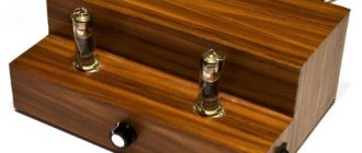
In this design, the main thing is not to forget that the threaded holes for transformers, amplifier board, lamp sockets and network connector must be placed inside the chassis. And everyone else goes outside. Thus, only TWO nuts are used in the design. They secured the octal socket under the load resistance switch. With great difficulty, a socket was found that is attached with a clamp. The panel is attached from the inside of the chassis. Only two M3 bolts with washers are visible from the outside (see photo).
Next, cut out the front and back bezels. After drilling them out, you must check that all the holes match the holes on the chassis. And if necessary, use a file to correct mismatched holes.
Painting the front panels should be done last. Painting technology may vary. One of them is described in my article on Datagor.ru.
Attention! The author used variable resistors with a bore diameter of 9 mm, input and output plastic connectors with a bore diameter of 10 mm, and toggle switches MT - 1, MT - 3 with a bore diameter of 6 mm. When using other parts, the holes for them will need to be adjusted.
↑ Design and details
Rice.
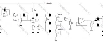
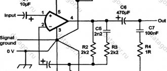
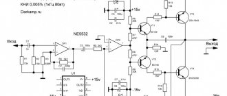
3. High-resolution board (click on the button to expand to full screen) Both channels of the amplifier, except for the power supply, are entirely mounted on one printed circuit board (Fig. 3). Since lamps dissipate quite a lot of heat, there is no point in trying to achieve a high installation density. For the same reason, it is advisable to use foiled fiberglass laminate as a material for a printed circuit board - this material is more temperature resistant than textolite or getinax, and does not deform when heated, which often happens with boards based on getinax.
Resistors can be BC or MLT types. R1-R5, R13 and R14 can be of any power (the printed circuit board is designed to install resistors such as BC-0.5 and MLT-0.5), R6, R7, R8, R11 and R12 are best taken with a power of at least 0.5 W (for R7 and R8 this is due not so much to the power dissipated on them, but to the possibility of “shooting through” between the threaded turns at the moment of power supply to the amplifier). R9 must have a power of at least 1 W, R10 - 2 W. It is best to take a wire R10 - also because of a possible breakdown at the moment of switching on, but in extreme cases, MLT-2 will also do. The resistances of resistors R1, R11-R14 can differ significantly from those indicated in the diagram: R1 can be from 100 kOhm to 1 MOhm; R13, R14 from 1 to 100 kOhm, but preferably the same resistance; resistance R11 can vary from 100 to 470 kOhm, and resistance R12 should be 5-15 times less than resistance R11. R7 can be from 2 to 8.2 kOhm. Resistance R10 should not be increased, but any resistors in the range from 100 to 220 Ohms can be used. The resistance of R6 can also vary - from 22 to 75 kOhm, however, it must be taken into account that when increasing the resistance of R6, it is necessary to increase the resistance of R4, as a result of which the depth of the feedback will slightly change, and therefore the sensitivity of the amplifier will change.
To set the required sensitivity, you will need to select resistance R5. Resistance R9 should not be changed - only as a last resort you can install a resistor with a resistance of 130 Ohms. The printed circuit board has two places for resistor R12 (indicated as R12“ on the wiring diagram), connected in parallel, so two resistors with a resistance greater than the nominal one can be used as R12. It would not hurt to select resistors R4, R5 and R9 for both channels in pairs with the closest resistance values - this will make it easier to configure the amplifier.
Capacitors C1, C2 and C4 are film. C1 and C2 type K73-9, C4 - K73-17. Capacitance C4 can be from 0.47 to 1.5 µF. The operating voltage of capacitors C1 and C2 is not critical (capacitors with a voltage of 100 V are used), the voltage of capacitor C4 must be at least 250 V. Other types of capacitors can be used, but it must be taken into account that, for example, metal-paper or mica capacitors will have much larger dimensions, and the use of ferroelectric capacitors in audio circuits is unacceptable due to the significant piezoelectric effect.
The use of unsealed capacitors (such as BMT, MBM) is also unacceptable due to the presence of large leakage currents in them. Electrolytic capacitors are absolutely not suitable. Power filter capacitors are any suitable electrolytic ones with an operating voltage of at least 300 V. Capacitance C3 should be at least 10 μF (however, in this case it is advisable to increase the resistance R7 to 5.1-6.2 kOhm), it is not advisable to reduce capacitance C5 ( in extreme cases, you can set 220 uF). It is also undesirable to reduce the capacitance of filter capacitor C7 in the power supply.
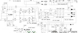
Diodes
The rectifier bridge can also be replaced with any others, it is only important that when the amplifier is turned on, they can withstand the charging current of the filter capacitors (up to
2 A
) and are designed for a reverse voltage of at least
400
V. Among the domestic ones, KD226G, D226, D226B are quite suitable.
Socket PL9—2
Socket PLC9
Modified socket PLC9
To place the lamps, sockets of the PL9-2
. Other sockets that can be installed on a printed circuit board are also suitable. If these are not available, you can use sockets that are not suitable for printed circuit mounting. To install them on the board, you can solder pieces of thick single-core wire to their terminals, with the help of which the socket will be installed on the board. However, it would be preferable to modify the socket terminals directly by biting off part of the terminal with sharp side cutters (nippers) (see photo).
JP1 jumpers are used from failed computer motherboards. The pins of the connector through which the signal is supplied to the amplifier input are of the same type. To connect the output transformer and power supply, pins are also mounted on the board - they are used from standardized connectors used in TVs. The wires to these pins are soldered, although the use of connectors is also possible. During installation, special attention should be paid to connecting to the common wire - all circuits of the common wire must be connected either at one point or in a strictly defined sequence. This sequence is observed on the printed circuit board - you just need to make sure that there are no “extra” connections.
The rated output power of the amplifier is 3 W, maximum 4 W, rated input voltage 0.75 V. This power is quite enough for comfortable listening to audio programs in a room of 30 m2 (using 6AC-224 speaker systems, from the “Cantata-205” radio set) .
↑ Amplifier assembly
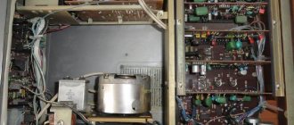
The amplifier assembly is clearly visible in the photographs in the article.
All parts are located on printed circuit boards. The exception is resistors located in cathodes and screen grids 6P14P. The ground wire first goes from the anode power board to the amplifier board at the point closest to the amplifier input. And then to all the other necessary places. The “ground” ends of the variable resistors are connected to each other by a thick bare copper wire and are connected to the “ground” wire at the input connectors. And from the input terminals “Earth” goes to the board. The result is a wiring that is as close as possible to a “Star” wiring. In general, land distribution is a complex matter. It requires knowledge of theory, a sense of smell, and even luck. My background turned out to be about 10 - 15 millivolts at the output. And this is with the level and tone controls fully engaged at the short-circuited input.
If anyone gets better results, I will be glad! Ground is connected to the case near the amplifier input point on the board. To do this, a petal is placed under one bolt securing the board. This is clearly visible in the photograph. The output stage operates in AB mode. The quiescent current of both lamps is about 70 mA. At the maximum signal, the anode current increases to 110 - 120 mA.
↑ Inlet filter - why?
A filter is applied at the amplifier input that does not allow low frequencies of the audio range to pass through to the amplifier input (from approximately 40 Hz and below).
The need for such a filter is caused by the following considerations: a) most middle-class household speaker systems have lower operating frequencies from 40 to 60 Hz and, in principle, are not capable of reproducing a signal with a frequency below this threshold - supplying a signal to the speaker system that is obviously lower than its minimum operating frequency is only generates significant additional distortion due to the displacement of speaker diffusers by this signal; b) domestic premises are small in size and, as a result, at low frequencies in such rooms there are many resonances that cause a “booming” effect during playback, and the smaller the room, the more pronounced this effect is, the higher the resonance appears at higher frequencies; c) as the frequency decreases, the amplifier power required for playback must increase (this is true for the entire frequency range) - for example, if 3 W is enough to play a signal with a normal volume of 100 Hz, then to play 50 Hz with the same volume you need more 12 W amplifier output power; d) the lower operating frequency of most industrial audio transformers is 40-50 Hz - at lower frequencies the transformer, as well as the speaker system, loses efficiency (this occurs due to the finite value of the inductance of the primary winding), and in combination with the higher power of the lower frequency the signal also generates significant distortion. Taking into account all this, as well as the fact that the output power of the single-ended amplifier stage on the 6P14P lamp is limited to 4.5 W, it was decided to use such a filter. Of course, if you use high-quality transformers and acoustic systems, then there is no need for such a filter. In this case, you can not mount it by removing R2 and replacing C2 with a jumper.
Looking ahead, I would like to note that when comparing the sound of an amplifier with and without a filter - subjective preference was always given to the version of the amplifier with a filter - the bass, contrary to forecasts, is more “elastic” due to the elimination of overload of the output stage and a significant reduction in the “mumbling” of the room.
↑ About replacing lamps
The closest parameters to the 6P14P lamp is 6P18P. In fact, the lamps are very close (in the absence of markings, they cannot be distinguished at all) and differ only, according to the reference book, in the nominal voltage at the anode, which for 6P18P is 170 V with a maximum allowable 250 V. However, 6P18P works great at higher voltages and can be installed instead of 6P14P without any changes in the circuit. Unfortunately, this is where the list of lamps suitable for such a replacement ends - for the remaining lamps it is necessary to select a cathode resistor. Lamps closest in parameters to 6P14P:
| Lamp | Anode current | Bias | R10 | Resistor power | output power |
| 6P15P | 35 mA | -2.5 V | 75 Ohm | 0.5 W | 2.5 W |
| 6P33P | 48 mA | -15 V | 270 Ohm | 2.0 W | 4.2 W |
It is possible to use a 6P1P lamp (with a 240 Ohm cathode resistor), but it has a different pinout, which entails the need to change the printed circuit board design. It is difficult to use a 6P43P lamp (although the pinout is the same) due to the large amount of bias required for its operation (for this lamp it is more profitable to use the so-called fixed bias from a separate source). The 6N3P lamp can be replaced without any modifications with a 6N26P lamp. Without changing the circuit, it is possible to use 6N1P, but it differs in pinout. 6N2P and 6N23P are of little use due to the low anode current of 6N2P (only 2.3 mA) and the strong microphone effect of 6N23P, but you can try using them, also taking into account their pinout (similar to the pinout of 6N1P)
↑ Precautions
1. During any installation work, the device must be de-energized.
Since the amplifier uses large-capacity storage capacitors, it is necessary to wait until they are discharged, which occurs within 30-40 seconds after the amplifier is turned off. When testing the power supply separately from the amplifier, be careful - in this case, capacitor C7 can store charge for a very long time (up to several days). To ensure the discharge of the capacitor, a resistor with a resistance of 100 kOhm to 1 MOhm and a power of at least 0.5 W should be temporarily soldered in parallel to it. It is strictly not recommended to discharge capacitors by short-circuiting their terminals (for example, with a screwdriver or tweezers) - this can lead to both failure of the capacitor and injury. 2. Tube amplifiers, unlike transistor amplifiers, are not afraid of a short circuit in the load, but a break in the load circuit can damage the output transformer. It is highly not recommended to turn on the amplifier without a rated load connected to its output (nominal load resistance 4...8 Ohms) - this risks breakdown of the insulation of the primary winding of the output transformer due to its significant inductance. If you are going to use the amplifier together with headphones, you need to take this into account and, while connecting the headphones, provide a parallel connection of an equivalent load, which can be a regular resistor with a resistance of 3.9 to 8.2 Ohms and a power dissipation of at least 2 W. Any load switching, during which even a short-term break in its circuit is possible, must be performed only with the amplifier power turned off.
3. The 6P14P output pentodes are very hot during operation. Don't get burned