This project examines headphone amplifiers based on mass-produced microcircuits, such as TDA2003, BA5415A and BA5417.
I refrained from philosophical discussions about which of the presented sound reproduction schemes is “more correct.” The purpose of the experiments is different - to provide worthy schemes for repetition, and enthusiastic readers will make their own choice and share their impressions.
↑ Headphone amplifier on TDA2003 chip
A review of amateur radio publications published in the magazine “Radiohobby” reports on Aren van Waerde’s successful experiment on using the widespread and cheap “automotive” microcircuit TDA2003 (analogue - K174UN14) as an amplifier for 32-ohm headphones, Fig. 1[1].
Rice. 1. Scheme of Arena van Waerde. Amplifier for stereo phones (one channel)
The author found that when powered from a unipolar 12 V source (quiescent current 40 mA), the amplifier operates in class A up to an output power of several hundred milliwatts. At the same time, the amplifier's transmission coefficient is reduced by more than five times compared to a typical microcircuit connection (from 100 to 18) without losing the stability of the circuit.
For such a simple circuit (Fig. 1) quite good characteristics were obtained:
Operating frequency range with characteristic unevenness ±3 dB: 14...30000 Nominal load impedance: 32 Ohm Harmonic distortion: 0.006% Noise level: –100 dB Maximum output power at 32 Ohm load: 200 mW Gain at 1000 Hz: 24.8 dB
Shown in Fig. 1 diagram is a basic topological one - it shows the connection point of common wires, which simplifies the implementation of the design “in hardware”.
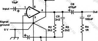
The corrected circuit diagram of the amplifier in a design familiar to the Russian radio amateur is shown in Fig. 2. Based on the results of prototyping, the amplitude-frequency response correction circuit R3, C5 is connected as recommended in a typical connection of the TDA2003 microcircuit, namely, between its pins 2 and 4.
Rice. 2. Adjusted amplifier circuit for stereo phones on TDA2003, TDA2002
The sensitivity from the input is about 100 mV, the amplifier is suitable for headphones with a resistance of 32 to 100 Ohms.
In position DA1 you can also install the TDA2002 chip. Resistors MLT, OMLT, S2-23, S2-29, S2-33N, MON or imported, with a power not lower than that indicated on the circuit diagram. Capacitors C3, C7 film type K73-17, K73-24 or imported MKT; capacitor C5 is ceramic. Choose high-quality oxide capacitors, designed for temperatures up to +105°C.
Amplifier parts, two channels
DA1 - TDA2003 chip - 2 pcs., R1 - Res.-0.125-130 Ohm - 2 pcs., R2, R3 - Res.-0.125-2.2 kOhm - 4 pcs., R4 - Res.-0.5- 1 Ohm - 2 pcs., C1 - Cond.10/25V 0511 105°C - 2 pcs., C2, C6 - Cond.470/25V 1013 105°C - 4 pcs., C3 - Cond.0.22/63V K73-17 - 2 pcs., C4 - Cond.1000/25v 1020+105°C - 2 pcs., C5 - Cond. 2200 pF NPO ceramic imp. - 2 pcs., C7 - Cond.0.1/63V K73-17 - 2 pcs., Terminal block TV-12A 2K pitch 5 mm per board - 6 pcs., Double variable resistor ALPS 33 - 50 kOhm - 1 pc., Resistor 1 kOhm 0.25 W - 2 pcs., Power cable ShVVP 2×0.75 - 0.5 m, Fluoroplastic wire MGTF 0.75 - 0.5 m, Heat-shrinkable tube d=5 mm - 0.5 m, Double asymmetrical shielded OFC cable 2×0.14 sq mm - 0 .5 m., Printed circuit board (for two channels) 96×38 mm - 1 pc.
Rice.
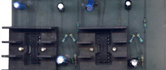
3(a) Placement of elements on a printed circuit board I recommend installing TDA2003 microcircuits on small radiators
25 mm high, cut from an aluminum profile for general construction purposes (channel) 10x20x10x2 mm.
Rice. 3(b) Connection diagram of an amplifier for stereo phones on a TDA2003 chip
Amplifier assembly on TDA2003
The entire circuit is assembled on a small printed circuit board measuring 45 x 55 mm, which can be made using the LUT method. The printed circuit board is completely ready for printing on a laser printer and does not require mirroring. After transferring the board, we put it in the etching solution and after etching we get the same result as in the photo below.
Now all that remains is to erase the toner layer, drill holes and tin the tracks and you can start soldering the parts. First of all, small parts are installed - resistors and small capacitors, then everything else. To connect the power wires, speaker and audio source, it is most convenient to use screw terminal blocks, which is what I did. Last but not least, a radiator is installed on the chip; you can use absolutely any one that fits the size of the board.
↑ Headphone amplifier on BA5415A chip
The BA5415A chip was included in the list of those recommended for use in a headphone amplifier by chance.
Our local poet and bard Sergei Alekseevich Krugovykh, inspired by another trip to Druksiai, was busy perpetuating his works on a personal computer, and complained to me about the lack of a headphone jack in his computer active speaker systems.
For those who don’t know, Druksiai is a picturesque place in Belarus, where every year, since August 1967, teams from Tallinn, Riga, Siauliai, Minsk, Moscow, Veliky Novgorod and other cities gather. These cheerful and friendly people come to meet and relax. The song competition “Druksiai Dawns” is traditional.
In order not to frighten the poet’s insight, I immediately began to improve his workplace: I purchased a telephone jack, found a dozen resistors (to be selected as current-limiting resistors at the output of the amplifier) and gave him my second TDS-5 headphones. The results of the upgrade exceeded all expectations - the sound in the headphones turned out to be extremely wonderful, so I sketched the diagram in my notebook (Fig. 4).
Rice. 4. Schematic diagram of a stereo headphone amplifier based on the BA5415A chip
Characteristics of the amplifier based on the BA5415A microcircuit from Rohm:
Output power: 3 W (4 Ohms) Sensitivity: 100...150 mV Input impedance: 47 kOhm Frequency range: 20...20000 Hz Load impedance: 3...250 Ohms Total harmonic distortion: 0.06% Signal-to-noise ratio: 86 dB (A) Quiescent current: 30mA
A volume control is installed at the input - a dual variable resistor with a resistance of 47 kOhm. The gain of a microcircuit with negative feedback can be set in the range of 33...45 dB by changing resistor R2 (R3) in the feedback circuit:
Ku=20lg[1+44/(R2(R3))], where R2 (R3) is the resistance of the external resistor, kOhm.
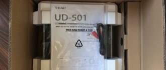
Later, on the Internet, I found information that the BA5415A (High - output dual power amplifier) chip is used in the ERGO AMP 1 headphone amplifier from the Swiss company Precide with an external power supply of 15...18 V/0.5 A, a volume control of 22 kOhm, fig. . 5. The external adapter contains a power transformer, and a diode bridge and a stabilized power supply (chip 7812, capacitors 5 × 1000 μF x 25 V = 5000 μF) are placed on the amplifier printed circuit board. Case dimensions 20x7x18 cm, weight 1.1 kg.
Rice. 5. Appearance of the ERGO AMP 1 headphone amplifier with the cover removed
The amplifier does not contain scarce components; they can be purchased at radio stores.
Elementary base of a headphone amplifier based on BA5415A
DA1 - Chip BA5415A - 1 pc., R1, R2 - Res.-0.25-33 kOhm - 2 pcs., R3...R6 - Res.-0.25-1.0 kOhm - 4 pcs., R7, R8 — Res.-0.5-1.5 Ohm — 2 pcs., C1, C2 — Cond. 10/25V 0511 +105°C — 2 pcs., C3…C6 — Cond. 100/25V 0812 +105°C — 4 pcs., C7, C8 — Metal film capacitor K73-17 imp, 0.1 uF, 63 V, 10%, POLYESTER BOXED, B32529C0104K000 — 2 pcs., C9, C11, C12 — Cond.1000/25V 1021+105 °C - 3 pcs., C10 - Cond. 220/25V 0812 105°C - 1 pc., 3k plug. on PLS-3 2.54 board - 1 pc., JP-2 jumper for pin strips and connectors, pitch 2.54 mm - 1 pc., Printed circuit board 75x50 mm - 1 pc.
The printed circuit board for the amplifier (Fig. 6) is designed based on the Data Sheet of the BA5415A chip.
Rice. 6. Placement of elements on the printed circuit board
The BA5415A stereo amplifier chip is installed on a small plate - a heat sink (Fig. 7).
Rice. 7. Heat sink for BA5415A chip. Material: duralumin 3…6 mm thick
First launch and tests
To begin with, it is worth checking the correctness of installation, ringing adjacent tracks for short circuits. If everything is assembled correctly, we supply power to the board by connecting the speaker and leaving the signal input unconnected. In this case, it is advisable to turn the volume control to the minimum position so that the input of the microcircuit is connected to ground. We supply power to the board, the LED should light up immediately.
Now we carefully turn the volume control; you should hear a slight crackling sound in the speaker, because the input is now “hanging in the air.” This means that the chip is working - now you can input music, for example, from a player, phone or computer. You can connect such an amplifier to any speakers with a resistance of 4-16 Ohms; the lower the speaker resistance, the greater the output power, and, accordingly, the heating of the microcircuit. Happy building!
Download PCB
Downloads: 219, size: 15.7 KB, date: 25.Feb.2019
↑ Headphone amplifier on BA5417 chip
Just like the previous one, the BA5417 microcircuit is designed for building amplifiers for radios and cassette players with a supply voltage from 6 to 15 V. The headphone amplifier circuit is shown in Fig. 8.
Rice. 8. Headphone amplifier based on BA5417 chip
In the BA5417 microcircuit, my attention was drawn to the presence of separate common signal “grounds” in each of the channels (pins 14 and 15 of the microcircuit), as well as a power common wire (pin 7 of the microcircuit), which allows us to hope for better amplifier characteristics.
The transmission coefficient of the feedback circuit (43...47 dB) is determined by the ratio of resistors inside the microcircuit and external resistors:
Ku=20lg[1+30000/(45+R1(R2))], where R1 (R2) is the resistance of the resistor, Ohm.
Capacitors C5 and C6 operate in “voltage booster” circuits; there are Zobel circuits (R3, C9 and R4, C10) to prevent self-excitation during the reactive nature of the load.
The microcircuit is equipped with a Stand by input; when its voltage is above 3.5 V, the operating mode is activated, and when the voltage is less than 1.2 V, the amplifier switches to low power consumption mode (20 μA).
Characteristics of the amplifier on the BA5417 chip:
Output power: 3.5 W (4 Ohm) Sensitivity: 20…50 mV Input impedance: 33 kOhm Reproducible frequency range: 20…20000 Hz Load resistance: 3…250 Ohm Nonlinear distortion factor (Rн=32 Ohm, Рout=0, 25 W): 0.08% Signal to noise ratio: 85 dB(A) Quiescent current: 22 mA
It should be remembered that the capacitance values of the oxide capacitors in the circuit affect the time it takes to establish the DC operating modes of the amplifier after turning on the power. With the capacitor ratings indicated in the diagram (Fig. it does not exceed 0.8 s.
Headphone amplifier parts for BA5417
DA1 - BA5417 chip, HSIP15 housing - 1 pc., R1, R2 - Res.-0.25-160 Ohm - 2 pcs., R3, R4 - Res.-0.5-2.2 Ohm - 2 pcs., R5, R6 — Res.-0.25-1.0 kOhm — 2 pcs., R7, R8 — Res.-0.5-1.5 Ohm — 2 pcs., C1, C2 — Cond. 10/25V 0511 +105°C — 2 pcs., C3, C4 — Cond. 330/25V 0812 +105°C — 2 pcs., C5, C6, C8 — Cond. 100/25V 0812 105°C — 3 pcs., C7, C11, C12 — Cond. 1000/25V 1321 (1021) +105°C — 3 pcs., C9, C10 — Cond. 0.15/63V K73-17 — 2 pcs., 3k plug. on PLS-3 2.54 board - 1 pc., JP-2 jumper for pin strips and connectors, pitch 2.54 mm - 1 pc., Printed circuit board 70x50 mm - 1 pc.
In Fig. Figure 9 shows the placement of parts on the amplifier printed circuit board on the BA5417 chip.
Rice. 9. Arrangement of elements on the amplifier printed circuit board
Try making two power supplies to practically evaluate its effect on the sound of the amplifier.
LM383 (TDA2003) chip packages
Lm3886: correct circuit and PCB
T0220 with five terminals. Both ICs are specifically designed for car audio applications, where at a normal operating voltage of 14.4 volts they have an output power of 5.5 watts into 4 ohms or 8.6 watts into 2 ohms. IC LM383 can supply current up to 3.5 A to the load, both ICs have load current limiting function and thermal protection of the output stage.
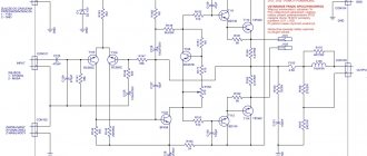
The LM383 (or TDA2003) integrated circuit is easy to use. The figure shows a practical circuit (with a circuit that increases high-frequency stability) designed for a simple 5.5-watt car audio amplifier. In this circuit, the gain is determined by the ratio of the negative feedback resistors 220 Ohm/2.2 Ohm and is 100;
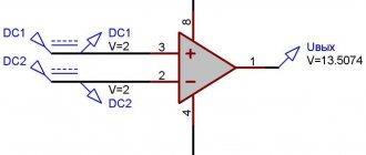
The IC operates in non-inverting mode, the input signal will be applied to pin 1 through a 10 µF electrolytic capacitor. The figure shows the circuit of an amplifier for a car, in which a pair of LM383 ICs or a TDA2003 amplifier is used to obtain an output power of 16 W. The trimmed resistor RV1 is required in this circuit to adjust the balance of the quiescent output voltages of both ICs and thereby ensures the minimum quiescent current of the circuit.
16-watt bridge amplifier based on IC LM383 (TDA2003) for a car.
TDA2003 is a monophonic low-frequency power amplifier (domestic analogue of K174UN14). The microcircuit develops a power of 10 W with a load resistance of 2 Ohms. The amplifier has a wide range of reproduced frequencies from 30Hz to 30KHz. The low-power amplifier is not equipped with polarity reversal protection; it is imperative to observe polarity when connecting to a power source.
TDA2003 is installed on a heat sink (radiator) with an area of at least 100 sq. The quiescent current of the microcircuit is 44mA. Supply voltage from 8V to 18V. It is not recommended to supply a signal with an amplitude of more than 1 Volt to the input of the microcircuit.
The audio power amplifier works excellently with any preamplifiers that meet all the technical parameters of the microcircuit. The amplifier is widely used in foreign car radios, as well as in portable household appliances, TVs, VCRs, etc.
↑ Power supply based on an integrated stabilizer with a fixed output voltage
made on the K142EN8B chip (12 V±3%), you can also supply K142EN8D (12 V±4%) or foreign LM7812.
The schematic diagram is shown in Fig. 10. The DA1 voltage stabilizer chip can be installed without a radiator, but experience suggests that it is better to install them on small radiators (TO-220 micro-Uheatsink).
Fig. 10. Schematic diagram of the power supply: C1…C4 type K73-17 for an operating voltage of 630 V; C6, C7 type K73-17 for operating voltage 63 or 250 V
Capacitors C1 - C4 bypass the bridge diodes VD1 - VD4, which makes it possible to suppress pulsed high-frequency interference, both generated by the bridge diodes and penetrating from the household network (~ 220 V, 50 Hz) through the step-down transformer T1.
Capacitors C5 and C6 are used for additional filtering of the output voltage, which ensures stable operation of the DA1 chip.
LED HL1 indicates the presence of output voltage. Chain R1, HL1 allows you to discharge the electrolytic capacitors of the power supply when there is no load.
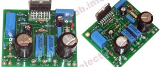
The power supply parts are located on the printed circuit board, Fig. eleven.
Rice. 11. Possible version of the power supply circuit board
see also
Comments 16
I remember we plugged these mikruhi into the bridge and used them to pump S90 speakers! ))
I'm sorry, but are the songs played one by one? And how to make a switch so that you can scroll through?)
This particular controller is programmed for signaling and file playback goes on and on. You can also make firmware by “flipping through” files.
Can I have a circuit that plays music from a flash drive?
Damn, I don’t know everything, does it need to be flashed or is it like a decoder?
Of course you need to flash it... I just don’t give out my firmware, although there are many different firmware options on the Internet...
I soldered it with pleasure, but with the programming language I’m on the fence, hey, you have a whitefish =) and he ran away and that’s it, once he studied it was interesting, but he was petty and stupid =(
In principle, I can flash the controller and send it... but it’s better to discuss this in PM...
You can make a stereo; the firmware is somewhere. then TDA2005 is possible. As I understand it, there is attini 85, then you can use the same octopus tda2822 as an amplifier. what is ITUN? what is it for?
Stereo is also possible, but I don’t have that task...
You won't surprise anyone with ITUN. but the “second part” (card reader) interested me.
so I say that “I didn’t discover America”, the whole trick is in the amount...