We present to your attention a simple tube amplifier that even a novice radio amateur can assemble. The developer of the amplifier is Anatoly Manakov, a recognized guru in the construction of tube circuits. The amplifier is assembled on just one 6F3P tube and can serve as an excellent start for those interested in tube technology and can be successfully used as an amplifier for home listening to music from a computer. Having assembled and configured the amplifier, I guarantee you that you will be surprised by the beauty and melody of its sound.
Characteristics:
- Output power - 2.5 W
- Frequency band - 30 - 20000 Hz
- Nonlinear distortion coefficient - 0.5-1%,
Don’t be confused by the seemingly small output power, but believe me, this will be quite enough for a home, and when using sensitive acoustics, the sound will be very loud. A good initial option would be to use acoustics with KinAp speakers: 4a32, 4a28 or modern wideband speakers such as Fostex.
Initially, you can assemble one channel on a breadboard for ease of experimentation, and then design it into a finished design with two channels for stereo listening.
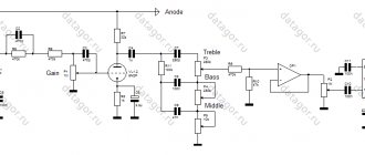
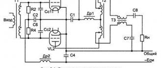
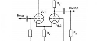
The amplifier contains two stages: the first is a preliminary stage, assembled on the triode part of the lamp, the second is the output stage, assembled on the tetrode half.
Amplifier Description
The input signal, through a variable volume control resistor, is supplied to the grid of the triode half of the 6F3P, amplified, then from the anode, through a separating capacitor, to the control grid of the output stage. The output stage operates in a triode connection, in which the screen grid of the 6F3P pentode is connected to the anode through a resistor with a resistance of 220 Ohms. In triode connection, the internal resistance of the lamp decreases, as a result of which the linear characteristic of the lamp improves, but the output power drops slightly.
The output stage is loaded on the famous TVZ-1-9 output transformer, which can be found in old tube TVs. You can use other output transformers of the TVZ series. It will also be necessary to make a gap; to do this, it is enough to disassemble the transformer hardware into two halves and lay a piece of ordinary office paper cut to size.
To replicate the amplifier, two 6F3P amplifier circuits are proposed, the first with a fixed, the second with automatic bias of the output stage, which do not differ much from each other.
Power supply diagram
It’s not the flames of the fire that are frying, or the sun has risen high, or with the diva-speakers the warm tube sound of the diva-6f3p-amplifier sings a song.
There are a lot of articles on the Internet about warm tube sound. So I was seduced into trying to put together something warm and luminous. After a short search, I decided that the optimal circuit for a beginning audiophile can be considered the Manakov circuit for 6f3p.
Introduction
The 6f3p circuit is well known, polished and has generally become a kind of classic. It is for these reasons that I decided to collect it. But unlike other DIYers, I decided to do it more or less uncompromisingly, but, at the same time, without engaging in complete audiophilia such as directivity of wires and capacitors for $100 apiece.
So, it was decided. Take Manakov’s circuit with an external bias of the output pentode, throw out the cheap TVZ transformers from it and make your own, true audiophile ones. It was also decided to abandon the remnants of the past - chokes in nutrition. Instead, semiconductor gyrators are used. Having read horror stories about the influence of variable resistors, I decided to put a position switch on the volume. In general, almost complete feng shui)
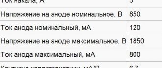
Data on these light bulbs can be found here.
Scheme
So, here is the diagram of my version.
CT on the diagram are control points. That is, the voltage there should be nominal. The K78-2 0.1uF/1000V is used as a “select” capacitor; it provided the best sound.
It seems that everything is simple. We wind True transformers. I couldn’t find cores from OSM-0.063, so I decided to use even cooler cores from OSM-0.1. Manakov helped calculate the output on these cores, for which honor and praise go to him. So here it is, the winding data
osm-01.txt - winding data for the output on OSM-0.1
Winding such transformers by hand is not a fun task, so I built some kind of winding machine, but still a winding machine.
Although it is primitive, it simplifies winding enormously. Winding is very simple - turn the handle and feed the wire with your hand.
Naturally, it’s easy to get lost in counting the turns, so I came up with this simple method. We roll the layer until it is filled, then we take a photo and in Photoshop we count the number of turns in the photo in a large approximation. Here is an example of one such photo:
We lay the wire turn-to-turn, using ordinary office paper as insulation.
So, the wire that went to the transformers together with the undisassembled OSM-0.1, halves of the magnetic circuit from the disassembled one and a micrometer.
After winding, “cook” the transformer in paraffin in a water bath for about an hour
When assembling, do not forget about the gaskets in the magnetic circuit and you get outputs like this.
Of the available power transformers, I chose TAN-2.
Now we assemble the power supply and bias regulator. Naturally, all this was previously simulated for a long time, tested, etc. A resistor would need to be added to the bias regulator for smooth adjustment, otherwise it would be a tedious task to measure the millimeters.
stab.pdf - anode supply stabilizer based on a gyrator
bias_regulator.pdf - bias regulator
What happened:
Assembling the layout
Although it looks unsightly, I selected lamps on it, checked the temperature conditions, etc.
Frame
And here the epic began. It’s not for nothing that they say that a radio amateur is first and foremost a carpenter, and then a radio amateur.
So, I model the body in SolidWorks
Beautiful, right? A month of fussing with a jigsaw, screws, glue and putty in the evenings and we get this good thing:
We cover it all with PVC film. Simple and beautiful, then we mount all our electronics inside. Naturally, the installation of signal circuits is mega-true, p2p. It looks terrible, but there are minimal leaks. Internal wiring of signal circuits is carried out using shielded wire.
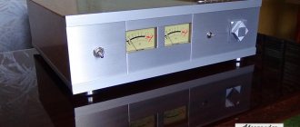
We collect and get a handsome guy:
Why XLR connectors? I already have speakers with these inputs. Those speakers that I have understand full balance. This same amplifier does not understand the balanced signal, so it uses only one component. If the cables are not very long, this does not affect anything - no noise is heard.
Sound
But here you probably expected rave reviews - they say it’s super, warm tube sound and all that. Nothing like this. It sounds well... uh... well, it just sounds! Acoustic compositions really sound better, denser, as if closer, but metal becomes a complete mess, and this really upset me.
Despite its 2.5W output power, the amplifier screams quite loudly. At maximum volume, neighbors get upset.
For sale (already sold)
Even though I've spent a lot of time and money on this amp, I don't use it. It sits on the nightstand and collects dust. So I decided to sell it. I’ll say right away that it may need to be modified - for example, adjusting the same offset adjustment (it stood for about a year, due to an error in the board that I described above, the adjustment could have floated away), or even make an automatic offset. In general, this is not a completely finished product, but rather a semi-finished product, despite the fact that it works quite well.
Since this is a craft, I am selling it at the price of the parts, not the price of the finished product.
So,
OSM-0.1 = 60 UAH * 2 = 120 UAH. TAN-2 = 50 UAH 6f3p = 20 UAH * 2 = 40 UAH XLR = 15 UAH * 2 = 30 UAH Capacitors 20 * 3 = 60 UAH Small things (transistors, small capacitors, biscuits, clamps for speaker wires, woodwork) for another 50 UAH. Total, 350 UAH
The money will be used to pay for hosting and other interesting projects.
Details
In the amplifier, you can use fixed resistors such as ULI, BC or MLT-0.5, as a separating capacitor C2 of type K 73-17, K71-7, K 78, K40 u9. In the power supply you can use power transformers and chokes from Soviet tape recorders and televisions.
For anode supply, use electrolytic capacitors K50-32 100 μFx350V, or imported ones for the same voltage. Instead of chokes, you can install MLT-2 resistors with a resistance of 250-300 Ohms, while doubling the capacity of the electrolytic capacitors. The capacitors in the bias rectifier are designed for a voltage of 50-100V.
When connecting an amplifier to a load of 8 ohms, you can use output transformers TVZ-1-1, TVZ-1-2. For a load of 4 ohms, use TVZ-1-9.
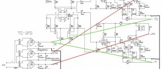
Diagram of a simple tube stereo UMZCH
I only changed a few elements - I added an additional CR link to the power supply filter and increased the capacitance of the last capacitor in the filter. This action was caused by combating the 100 Hz hum.
I advise everyone in the future to first start the amplifier without a regulator, and if everything is in order, then connect it too. In addition, I increased the capacitance of the capacitor connecting the pentode grid to the triode anode, and replaced the potentiometers with resistors. TS40/29/676 serves as a power transformer and 2 audio TG2.5-1-666 for speakers per channel. The mass is arranged in the style of a star. The filament is not straightened or balanced - as it turns out, it has no effect.
The anode voltage of the pentode is 270 V, and that of the triode is 210 V. All elements are mounted directly on the sockets. Body made from found pine boards, 2 mm metal sheet. Transformer covers are also made of chipboard. Installation and setup did not cause much trouble - the ULF started playing from the very first turn on.
Of course, we couldn’t do without an indicator on the EM84 radio tube, which pleases the eye by blinking in time with the music. Here is the circuit that I used to control the EM84 radio tube:
I just increased the value of the anode resistor to 600 kOhm, and now the petals glow without a signal for a length of about 3 mm.
Well, then I took an oscilloscope and made basic measurements of the amplifier. Test load in the form of an 8.2 Ohm resistor, and here are the results:
- RMS power: 2 W (read at initial sine wave distortion)
- Frequency response: 21 Hz – 19.7 kHz @ -3 dB, 26 Hz – 19 kHz @ -1.5 dB
I think that installing a higher-quality audio transformer, for example TG5, will expand the frequency response band, especially at the top. Definitely worth trying to get your hands on one.
The amplifier consumes about 50 W from the network, regardless of whether it is playing or not - class A is class A))
Amplifier settings
With proper installation and a working lamp, the first stage does not require adjustment. Setting up the second stage consists of adjusting the lamp's quiescent current within 40-45 mA at the control point in the cathode. The voltage drop across a cathode resistor with a resistance of 1 Ohm should be about 0.04-0.045 V. When manufacturing an amplifier version with automatic bias, the cathode resistors should be selected so that the current flowing through the output stage lamp is equal to 40-45 mA, the voltage drop across these resistors will be within 20-25 V.