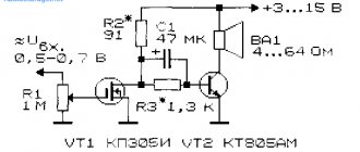
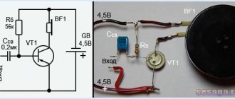
How ULF works
To reliably protect the loudspeaker from the constant component of the output stage, an autonomous rectifier is used, in which, unlike a bipolar rectifier, there is no potential midpoint connected to a common grounded wire.
Its functions in terms of the variable component of the output signal are performed by the middle point of series-connected capacitors C5, C6. The power amplifier is balanced automatically by connecting the non-inverting input - the base of transistor VT1 to the midpoint of the resistive supply voltage divider (R2, R3). Since transient processes in circuits with a common time constant are mutually compensated, the “rumble” signal does not occur either when the power is turned on and off, or during voltage fluctuations in the network.
The quiescent current of the output transistors VT9, VT10 is stabilized by transistors VT11, VT12, which operate (for the collector current of transistors VT5 - VT6) as a shunt controlled by the quiescent current. Such a transistor shunt not only protects the output transistors from such overload, but also significantly smoothes the switching pulses even in the minimum quiescent current mode.
Work in intermediate classes
Each class has several varieties. For example, there is a class of amplifiers “A+”. In it, the input transistors (low voltage) operate in mode “A”. But high-voltage ones installed in the output stages operate either in “B” or “AB”. Such amplifiers are much more economical than those operating in class “A”. A noticeably smaller number of nonlinear distortions is not higher than 0.003%. Better results can be achieved using bipolar transistors. The operating principle of amplifiers based on these elements will be discussed below.
But there is still a large number of higher harmonics in the output signal, causing the sound to become characteristically metallic. There are also amplifier circuits operating in class “AA”. In them, nonlinear distortions are even less - up to 0.0005%. But the main drawback of transistor amplifiers still exists - the characteristic metallic sound.
Amplifier operating class
As is known, depending on the degree of continuity of current flow during its period through a transistor amplifier stage (amplifier), the following classes of its operation are distinguished: “A”, “B”, “AB”, “C”, “D”.
In operating class, current “A” flows through the cascade for 100% of the input signal period. The operation of the cascade in this class is illustrated by the following figure.
In the operating class of the amplifier stage “AB”, the current flows through it for more than 50%, but less than 100% of the input signal period (see figure below).
In the “B” stage operation class, the current flows through it for exactly 50% of the input signal period, as illustrated in the figure.
And finally, in the “C” stage operation class, the current flows through it for less than 50% of the input signal period.
Transformerless transistor power amplifier
Transformers, despite the successes in their miniaturization, still remain the most bulky, heaviest and most expensive electronic devices. Therefore, a way was found to eliminate the transformer from the push-pull circuit by performing it on two powerful complementary transistors of different types (npn and pnp). Most modern power amplifiers use precisely this principle and are designed to operate in class “B”. The circuit of such a power amplifier is shown in the figure below.
Both of its transistors are connected according to a circuit with a common collector (emitter follower). Therefore, the circuit transfers the input voltage to the output without amplification. If there is no input signal, then both transistors are on the border of the on state, but they are turned off.
When a harmonic signal is applied to the input, its positive half-wave opens TR1, but puts the pnp transistor TR2 completely in cutoff mode. Thus, only the positive half-wave of the amplified current flows through the load. The negative half-wave of the input signal opens only TR2 and closes TR1, so that the negative half-wave of the amplified current is supplied to the load. As a result, a full power-amplified (due to current amplification) sinusoidal signal is released at the load.
Low frequency amplifier circuit. Classification and principle of operation of ULF
Low frequency amplifier (hereinafter referred to as ULF) is an electronic device designed to amplify low frequency oscillations to the one required by the consumer. They can be performed on various electronic elements such as different types of transistors, lamps or operational amplifiers.
- Low frequency amplifier circuit. Classification and principle of operation of ULF
- Options
- Amplifier operating principle
- Transistor amplifier: types, circuits, simple and complex
- Frequency characteristics
- Classes of operation of audio amplifiers
- The presence of distortion in various classes of low-frequency amplifiers
- Work in intermediate classes
- "Alternative" designs
- Table of amplifier classes by conduction angle
- Scope of application
- Sources:
Push-pull audio amplifier
A push-pull LF amplifier with two transistors splits the input audio signal into two antiphase half-waves, each of which is amplified by its own transistor stage. After performing such amplification, the half-waves are combined into a complete harmonic signal, which is transmitted to the speaker system. Such a transformation of the low-frequency signal (splitting and re-merging), naturally, causes irreversible distortion in it, due to the difference in the frequency and dynamic properties of the two transistors of the circuit. These distortions reduce the sound quality at the amplifier output.
Push-pull amplifiers operating in class “A” do not reproduce complex audio signals well enough, since a direct current of increased magnitude continuously flows in their arms. This leads to asymmetry of signal half-waves, phase distortion and ultimately loss of sound intelligibility. When heated, two powerful transistors double the signal distortion in the low and infra-low frequencies. But still, the main advantage of the push-pull circuit is its acceptable efficiency and increased output power.
A push-pull transistor power amplifier circuit is shown in the figure.
This is an amplifier for operation in class “A”, but class “AB” and even “B” can be used.
Options
- current gain = output current / input current;
- voltage gain = output voltage / input voltage;
- Power gain = output power / input power.
For some devices, such as operational amplifiers, the value of this coefficient is very large, but working with too large (as well as too small) numbers in calculations is inconvenient, so gains are often expressed in logarithmic units.
The following formulas are used for this:
- power gain in logarithmic units = 10 * decimal logarithm of the desired power gain;
- current gain in logarithmic units = 20 * decimal logarithm of the desired current gain;
- voltage gain in logarithmic units = 20 * decimal logarithm of the desired voltage gain;
- signal distortion factor.
The coefficients calculated in this way are measured in decibels. The abbreviated name is dB.
Types of power:
- Nominal.
- Passport noise.
- Maximum short-term.
- Maximum long-term.
DIY transistor audio amplifier circuit
The range of sound frequencies that are perceived by the human ear is in the range of 20 Hz-20 kHz, but a device made on a single semiconductor device, due to the simplicity of the circuit and the minimum number of parts, provides a narrower frequency band. In simple devices, a frequency range of 100 Hz-6,000 Hz is sufficient for listening to music. This is enough to play music on a miniature speaker or earphone. The quality will be average, but quite acceptable for a mobile device.
The circuit of a simple audio amplifier using transistors can be assembled using silicon or germanium products of direct or reverse conduction (pnp, npn). Silicon semiconductors are less critical to supply voltage and have less dependence of characteristics on junction temperature.
Amplifier frequency response
In any television or radio receiver, in every music center or sound amplifier, you can find transistor sound amplifiers (low frequency - LF). The difference between transistor audio amplifiers and other types lies in their frequency characteristics.
A transistor-based audio amplifier has a uniform frequency response in the frequency band from 15 Hz to 20 kHz. This means that the amplifier converts (amplify) all input signals with a frequency within this range approximately equally. The figure below shows the ideal frequency response curve for an audio amplifier in the coordinates “amplifier gain Ku – input signal frequency.”
This curve is almost flat from 15 Hz to 20 kHz. This means that such an amplifier should be used specifically for input signals with frequencies between 15 Hz and 20 kHz. For input signals with frequencies above 20 kHz or below 15 Hz, its efficiency and performance degrade quickly.
The type of frequency response of the amplifier is determined by the electrical radio elements (ERE) of its circuit, and primarily by the transistors themselves. A transistor-based audio amplifier is usually assembled using so-called low- and mid-frequency transistors with a total input signal bandwidth from tens and hundreds of Hz to 30 kHz.
Single-ended ULF circuit on a transistor
The simplest amplifier, built according to a common emitter circuit, operates in class “A”. The circuit uses a semiconductor element with an npn structure. A resistance R3 is installed in the collector circuit, limiting the flow of current. The collector circuit is connected to the positive power wire, and the emitter circuit is connected to the negative wire. If you use semiconductor transistors with a pnp structure, the circuit will be exactly the same, you just need to change the polarity.
We recommend reading: Refinement of the Chinese super bright flashlight UltraFire XML-T6
Using a decoupling capacitor C1, it is possible to separate the alternating input signal from the direct current source. In this case, the capacitor is not an obstacle to the flow of alternating current along the base-emitter path. The internal resistance of the emitter-base junction together with resistors R1 and R2 represent the simplest supply voltage divider. Typically, resistor R2 has a resistance of 1-1.5 kOhm - the most typical values for such circuits. In this case, the supply voltage is divided exactly in half. And if you power the circuit with a voltage of 20 Volts, you can see that the value of the current gain h21 will be 150. It should be noted that HF amplifiers on transistors are made according to similar circuits, only they work a little differently.
In this case, the emitter voltage is 9 V and the drop in the “E-B” section of the circuit is 0.7 V (which is typical for transistors on silicon crystals). If we consider an amplifier based on germanium transistors, then in this case the voltage drop in the “E-B” section will be equal to 0.3 V. The current in the collector circuit will be equal to that flowing in the emitter. You can calculate it by dividing the emitter voltage by resistance R2 – 9V/1 kOhm=9 mA. To calculate the value of the base current, you need to divide 9 mA by the gain h21 - 9 mA/150 = 60 μA. ULF designs usually use bipolar transistors. Its operating principle is different from field ones.
On resistor R1, you can now calculate the drop value - this is the difference between the base and supply voltages. In this case, the base voltage can be found using the formula - the sum of the characteristics of the emitter and the “E-B” transition. When powered from a 20 Volt source: 20 – 9.7 = 10.3. From here you can calculate the resistance value R1 = 10.3 V/60 μA = 172 kOhm. The circuit contains capacitance C2, which is necessary to implement a circuit through which the alternating component of the emitter current can pass.
If you do not install capacitor C2, the variable component will be very limited. Because of this, such a transistor-based audio amplifier will have a very low current gain h21. It is necessary to pay attention to the fact that in the above calculations the base and collector currents were assumed to be equal. Moreover, the base current was taken to be the one that flows into the circuit from the emitter. It occurs only if a bias voltage is applied to the base output of the transistor.
But it must be taken into account that collector leakage current absolutely always flows through the base circuit, regardless of the presence of bias. In common emitter circuits, the leakage current is amplified by at least 150 times. But usually this value is taken into account only when calculating amplifiers based on germanium transistors. In the case of using silicon, in which the current of the “K-B” circuit is very small, this value is simply neglected.
Single-ended amplifier with MOS transistor
Like any amplifier based on field-effect transistors, the circuit in question has its analogue among amplifiers based on bipolar transistors. Therefore, let's consider an analogue of the previous circuit with a common emitter. It is made with a common source and RC connections for input and output signals for operation in class “A” and is shown in the figure below.
Here C1 is the same decoupling capacitor, through which the AC input signal source is separated from the DC voltage source Vdd. As you know, any amplifier based on field-effect transistors must have the gate potential of its MOS transistors lower than the potentials of their sources. In this circuit, the gate is grounded by resistor R1, which usually has a high resistance (from 100 kOhm to 1 Mohm) so that it does not shunt the input signal. There is practically no current passing through R1, so the gate potential in the absence of an input signal is equal to the ground potential. The source potential is higher than the ground potential due to the voltage drop across resistor R2. Thus, the gate potential is lower than the source potential, which is necessary for normal operation of Q1. Capacitor C2 and resistor R3 have the same purpose as in the previous circuit. Since this is a common source circuit, the input and output signals are 180° out of phase.
Audio amplifier circuit
A higher quality ULF can be assembled using two devices.
The amplifier circuit with two transistors includes more components, but can operate with a low input signal level, since the first element acts as a preliminary stage.
An alternating audio frequency signal is supplied to potentiometer R1, which plays the role of a volume control. Next, through an isolation capacitor, the signal is supplied to the base of the first stage element, where it is amplified to a value that ensures normal operation of the second stage. The collector circuit of the second semiconductor includes a sound source, which can be a small-sized earphone. The bias on the bases is set by resistors R2 and R4. In addition to KT 315, any low-power silicon semiconductors can be used in the audio amplifier circuit with two transistors, but depending on the type of products used, selection of bias resistors may be required. If you use a push-pull output, you can achieve a good volume level and good frequency response. This circuit is made on three common KT 315 silicon devices, but other semiconductors can be used in the device. The big advantage of the circuit is that it can operate on a low-impedance load. Miniature speakers with a resistance of 4 to 8 ohms can be used as a sound source.
The device can be used in conjunction with a player, tuner or other household appliance. The supply voltage of 9 V can be obtained from a Krona battery. If you use KT 815 in the output stage, then at a 4 ohm load you can get up to 1 watt of power. In this case, the supply voltage will need to be increased to 12 volts, and the output elements will need to be mounted on small aluminum heat sinks.
We recommend reading: MOSFET transistors - what they are, operating principle
Amplifier with transformer output
The third single-stage simple transistor amplifier, shown in the figure below, is also made according to a common-emitter circuit for operation in class “A”, but it is connected to a low-impedance speaker through a matching transformer.
The primary winding of transformer T1 loads the collector circuit of transistor Q1 and develops the output signal. T1 transmits the output signal to the speaker and matches the transistor's output impedance to the low (on the order of a few ohms) impedance of the speaker.
The voltage divider of the collector power supply Vcc, assembled on resistors R1 and R3, ensures the selection of the operating point of transistor Q1 (supplying a bias voltage to its base). The purpose of the remaining elements of the amplifier is the same as in the previous circuits.
Audio power amplifier chips in bulk
Check current price or buy
Most AB class ULF microcircuits have a design that is convenient for installation in amateur radio structures, even with wired installation.
In this regard, when no ready-made board is suitable for the intended design, you can develop your own board; and buy microcircuits for it separately, since bulk microcircuits are so cheap that they are most often sold not individually, but in sets of 2 - 10 pieces.
Using the link provided, you can purchase UMZCH microcircuits in sets of 5 pieces of the same name.
These are TDA7385 (4 bridge channels of 30 W each), TDA7388 (4 bridge channels of 41 W each), TDA7850 (4 bridge channels of 50 W each, MOSFET), TDA7851 (4 bridge channels of 48 W each, MOSFET).
Price - from $6.3 to $11.5 for 5 pieces. depending on the name.
Class AB amplifiers based on single-chip microcircuits have proven to be a solid and time-tested solution with high sound quality.
The output power of such microcircuits can be very significant.
In fact, if the consumer does not need to design equipment for sound recording of stadiums and concert halls, then for all other household needs designs based on such microcircuits will be quite sufficient.
In addition, it should be noted that they contain various types of protection (from overheating, from overcurrent, etc.), and also have high-quality thermal stabilization of modes due to the fact that the temperature sensor and the heat source are located in close proximity (on the same substrate ).
That is, with a power of up to 100 - 150 W, there is no need to assemble an amplifier from discrete elements.
The single-board amplifiers described in the selection can be used both for repairing radio equipment and for creating independent structures; including, for example, to revive “old Soviet” speakers (many of which are still alive and well among the population); or to return into operation “orphaned” speakers from radios and music centers after irreparable failure of the main device.
If the goods indicated in the descriptions are found cheaper from other sellers on Aliexpress, then you can also take them - the goods are the same (but you need to keep an eye on the shipping costs).
"Alternative" designs
This is not to say that they are alternative, but some specialists involved in the design and assembly of amplifiers for high-quality sound reproduction are increasingly giving preference to tube designs. Tube amplifiers have the following advantages:
- Very low level of nonlinear distortion in the output signal.
- There are fewer higher harmonics than in transistor designs.
But there is one huge disadvantage that outweighs all the advantages - you definitely need to install a device for coordination. The fact is that the tube stage has a very high resistance - several thousand Ohms. But the speaker winding resistance is 8 or 4 ohms. To coordinate them, you need to install a transformer.
Of course, this is not a very big drawback - there are also transistor devices that use transformers to match the output stage and the speaker system. Some experts argue that the most effective circuit is a hybrid one - which uses single-ended amplifiers that are not affected by negative feedback. Moreover, all these cascades operate in ULF class “A” mode. In other words, a power amplifier on a transistor is used as a repeater.
Moreover, the efficiency of such devices is quite high - about 50%. But you should not focus only on efficiency and power indicators - they do not indicate the high quality of sound reproduction by the amplifier. The linearity of the characteristics and their quality are much more important. Therefore, you need to pay attention primarily to them, and not to power.
Amplifier assembly
The circuit is assembled on a printed circuit board measuring 50x40 mm, a drawing in Sprint-Layout format is attached to the article. The given printed circuit board must be mirrored when printing. After etching and removing toner from the board, holes are drilled, it is best to use a 0.8 - 1 mm drill, and for holes for output transistors and a terminal block 1.2 mm. After drilling the holes, it is advisable to tin all the tracks, thereby reducing their resistance and protecting the copper from oxidation. Then small parts are soldered in - resistors, diodes, followed by output transistors, terminal block, capacitors. According to the diagram, the collectors of the output transistors must be connected; on this board, this connection occurs by shorting the “backs” of the transistors with a wire or a radiator, if one is used. A radiator must be installed if the circuit is loaded onto a speaker with a resistance of 4 Ohms, or if a high volume signal is supplied to the input. In other cases, the output transistors hardly heat up and do not require additional cooling. After assembly, be sure to wash off any remaining flux from the tracks and check the board for assembly errors or short circuits between adjacent tracks.
power unit
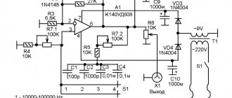
The figure below shows a diagram of a power supply - a source of several auxiliary voltages. It is not required to operate the power amplifier itself, but is very useful for powering the rest of the complete audio complex, such as the preamplifier, fans, level indicator, soft start system or speaker protection. All these modules are integrated into one common amplifier in a large housing.
Power supply for ULF auxiliary voltage - diagram
The power supply is divided into several separate sections, each of which has its own separate ground circuit. The first section is a symmetrical 2x15V power supply, it is used to power the preamplifier. Connector A4 is used to connect a bipolar transformer winding. The voltage is rectified using bridge rectifier Br2 (1 A) and filtered by stabilizers U2 (LM317), U6 (LM337) using C1 (100nF), C7 (100nF) and C24-C25 (4700uF). The output filter is capacitors C8-C9 (100nF) and C19-C20 (100uF). The output voltage of this block is set using resistors R2-R3 (220R) and R9-R10 (2.4 k). Transistors T1 (BC546), T2 (BC556); resistors R4-R5 (10k) and R7-R8 (3.3 k) represent a power cut-off circuit, or rather, they reduce the supply voltage to 2 × 1.25 V, which will allow the preamplifier to be turned off. During normal operation, shorting the GP8 connector will ensure proper operation of the preamplifier.
Useful: 220 V network switch controlled by IR remote control
PCB printed circuit board - drawing
The next two modules are 12 V power supplies, assembled using stabilizers U4 (7812) and U5 (7812) and intended to power other circuit elements. Two separate sources are necessary because the amplifier has two pairs of level meters, each on a separate ground. One pair works at the input, monitoring the input signal level, and the second pair is connected to the output and allows you to determine the current power level of the UMZCH.
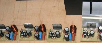
Power supply circuit board - after etching and drilling
Both power supplies are very simple, the first consists of a diode bridge Br3 (1A), filter capacitors C5-C6 (100nF), C18 (100uF) and C22 (1000uF) and a stabilizer U4. The transformer windings must be connected to connector A2, and the output of the power supply will be connectors GP6 and GP7.
The second 12V channel works exactly the same, and consists of elements: Br4 (1A), C10-C11 (100nF), C23 (1000uF), C21 (100uF) and U5.
The last module of the power supply system is the power supply circuits for other amplifier devices and cooling fans. A transformer should be connected to connector A1. The voltage is rectified using bridge rectifier Br1 (5A) and filtered by capacitors C27 (4700uF), C12 (4700uF) and C2 (100nF). The U1 microcircuit (LM317) works here as a stabilizer, which sets the required voltage using resistors R1 (220R) and R6 (2.7 k).
Capacitors C3 (100nF) and C16 (100uF) filter the voltage at the output of the stabilizer, which enters the fan control system through connectors GP1 and GP2. The same voltage is supplied through diode D1 (1N5819) to stabilizer U3 (7812), whose task is to provide power to other amplifier devices connected to connectors GP3-GP5. Capacitors C28 (4700uF), C13 (4700uF), C4 (100nF) and C17 (100uF) filter the voltage before the stabilizer.
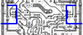
ULF printed circuit board - drawing
The printed circuit board is available for free download to all visitors to the 2shemi.ru . There are two jumpers on the board, from which it must be made with strong wire at the amplifier output. The order of assembly is arbitrary, but, as usual, it is worth starting with small resistors and capacitors. At the very end, you should solder the power transistors and large filter capacitors.
Ready ULF printed circuit board - all that remains is to solder the parts
Power transistors must be equipped with flanges for bolts for mounting through insulating gaskets together with T7 on a common radiator. In this case, it is necessary to take special care and check with an ohmmeter that none of the transistors has a short to the radiator. The radiator must be connected to the amplifier ground. Paths for the passage of large currents should be reinforced from below with thick copper wire. It is better to power the amplifier from a 600VA 2×55V transformer, which after rectification and filtering will give a voltage of about +/-80V on the capacitors.
Will need
Power transistors and operational amplifier:
- 2SC5200 Transistors x 5 - https://ali.pub/4xjey2
- 2SA1943 Transistors x 5 - https://ali.pub/4xjf1k
- Op-amp HA17741 x 1 - https://ali.pub/4xjf4h
Other components: Show/Hide text
- SC 2SC2073 Transistors x 2.
- S 2SA940 Transistors x 2.
- 3 0.33/5 W resistors x 10.
- 4.7/1W resistors x 10.
- resistors 10/2 W x 2.
- resistors 100/1 W x 6.
- resistors 330/1 W x 2.
- 10 resistors x 1.
- 100 resistors x 1.
- 1K resistors x 1.
- 5K6 resistors x 2.
- resistors 10K x 2.
- 47K resistors x 1.
- resistors 100K x 1.
- 33P capacitors x 1.
- capacitors 220P x 4.
- 680P capacitors x 1.
- 0.1 uF capacitors x 1.
- 10uF/50V capacitors x 2.
- 100uF/25V capacitors x 3.
- 10,000 µF / 80 V capacitors x 2 or x 4.
- Diode 4148 x 2.
- Diode bridge 35A X 1.
- Zener diode 15V X 2.
- Coil 16 turns (copper wire with a diameter of 1.5 mm).
- 50K Potentiometers x 1.
- Mica insulation of transistors x 10.
- Aluminum radiator x 1.
- Transformer 45 - 50 VAC 2 x 30A.
We recommend reading: The simplest 220 volts without a driver (the simplest way to power an LED from a 220V network)
Amplifier setup and testing
Once assembly is complete, you can apply power to the amplifier board. An ammeter must be connected to the gap in one of the supply wires to monitor the current consumption. We apply power and look at the ammeter readings; without applying a signal to the input, the amplifier should consume approximately 15-20 mA. The quiescent current is set by resistor R6; to increase it, you need to reduce the resistance of this resistor. The quiescent current should not be increased too much, because The heat generation on the output transistors will increase. If the quiescent current is normal, you can apply a signal to the input, for example, music from a computer, phone or player, connect a speaker to the output and start listening. Although the amplifier is simple in design, it provides very acceptable sound quality. To play two channels simultaneously, left and right, the circuit must be assembled twice. Please note that if the signal source is located far from the board, it must be connected with a shielded wire, otherwise interference and interference will not be avoided. Thus, this amplifier is completely universal due to its low current consumption and compact board size. It can be used both as part of computer speakers and when creating a small stationary music center. Happy assembly.
Single transistor amplifier
To understand the above, let’s assemble a simple amplifier using transistors with our own hands and figure out how it works.
As a load for a low-power transistor T of type BC107, we will turn on headphones with a resistance of 2-3 kOhm, apply a bias voltage to the base from a high-resistance resistor R* of 1 MOhm, and connect a decoupling electrolytic capacitor C with a capacity of 10 μF to 100 μF into the base circuit T. Power the circuit We will use 4.5 V/0.3 A from the battery.
If resistor R* is not connected, then there is neither base current Ib nor collector current Ic. If a resistor is connected, the voltage at the base rises to 0.7 V and a current Ib = 4 μA flows through it. The current gain of the transistor is 250, which gives Ic = 250Ib = 1 mA.
Having assembled a simple transistor amplifier with our own hands, we can now test it. Connect the headphones and place your finger on point 1 of the diagram. You will hear a noise. Your body perceives power supply radiation at a frequency of 50 Hz. The noise you hear from your headphones is this radiation, only amplified by a transistor. Let us explain this process in more detail. A 50 Hz AC voltage is connected to the base of the transistor through capacitor C. The base voltage is now equal to the sum of the DC offset voltage (approximately 0.7 V) coming from resistor R* and the AC finger voltage. As a result, the collector current receives an alternating component with a frequency of 50 Hz. This alternating current is used to shift the speaker membrane back and forth at the same frequency, meaning that we will be able to hear a 50Hz tone at the output.
Listening to a noise level of 50 Hz is not very interesting, so you can connect low-frequency signal sources (CD player or microphone) to points 1 and 2 and hear amplified speech or music.
The presence of distortion in various classes of low-frequency amplifiers
The working area of a class “A” transistor amplifier is characterized by fairly small nonlinear distortions. If the incoming signal spits out higher voltage pulses, this causes the transistors to become saturated. In the output signal, higher ones begin to appear near each harmonic (up to 10 or 11). Because of this, a metallic sound appears, characteristic only of transistor amplifiers.
If the power supply is unstable, the output signal will be modeled in amplitude near the network frequency. The sound will become harsher on the left side of the frequency response. But the better the stabilization of the amplifier's power supply, the more complex the design of the entire device becomes. ULFs operating in class “A” have a relatively low efficiency - less than 20%. The reason is that the transistor is constantly open and current flows through it constantly.
To increase (albeit slightly) efficiency, you can use push-pull circuits. One drawback is that the half-waves of the output signal become asymmetrical. If you transfer from class “A” to “AB”, nonlinear distortions will increase by 3-4 times. But the efficiency of the entire device circuit will still increase. ULF classes “AB” and “B” characterize the increase in distortion as the signal level at the input decreases. But even if you turn up the volume, this will not help completely get rid of the shortcomings.
Return to the Class A transistor amplifier?
Today, many experts in the field of high-quality sound reproduction advocate a return to tube amplifiers, since the level of nonlinear distortions and higher harmonics they introduce into the output signal is obviously lower than that of transistors. However, these advantages are largely offset by the need for a matching transformer between the high-impedance tube output stage and low-impedance audio speakers. However, a simple transistor amplifier can be made with a transformer output, as will be shown below.
There is also a point of view that the maximum sound quality can only be provided by a hybrid tube-transistor amplifier, all stages of which are single-ended, are not covered by negative feedback and operate in class “A”. That is, such a power repeater is an amplifier with one transistor. Its circuit can have a maximum achievable efficiency (in class “A”) of no more than 50%. But neither the power nor the efficiency of the amplifier are indicators of the quality of sound reproduction. In this case, the quality and linearity of the characteristics of all ERE in the circuit acquire special importance.
Since single-ended circuits are gaining this perspective, we will look at their possible variations below.