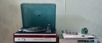
Modification of Amfiton 25 AS-027
There is a lot of information on the modification of USSR acoustics, but I couldn’t find any on the modification of the Amphiton 25 AS-027. Since I am the owner of this acoustics, I want to share my experience in its modification. Basically, the ideas were taken from modifications of other speakers, tips from friends and communication on forums.
I wanted to buy these speakers for a long time, but I bought them only in 2009, second-hand (for $68 at those rates). There is only one reason for the purchase - isodynamic HF, but you can also add 50 GDN to them and a good case. When purchasing, I compared it with the S-90 and S-90D, Amphiton won in low and high frequencies.
Passport information according to AS:
Reproducible frequency range: 25 (-17dB) – 31500 Hz Frequency response unevenness in the range 100-8000 Hz: ± 4 dB Sensitivity: 86 dB Total electrical resistance: 4 Ohm Minimum electrical resistance: 3.2 Ohm Maximum noise power: 50 W Weight: 25 kg Dimensions: (HxWxD): 60x32x27 cm
The bass reflex tube has dimensions: diameter 55 mm and length 165 mm, tuning frequency 25-30 Hz. The internal volume of the speaker is 41 liters. Frequency range: 500 and 3000 Hz. Speakers: 50 GDN-3, 20 GDS-3 and 25 GDV-1 (10 GI-1-4).
Shapes of the frequency response of sound pressure measured along the axis, curve 1:
The amplitude-frequency characteristics of harmonic distortions for the 2nd and 3rd harmonics are presented in the photo, curves 2 and 3. Harmonic distortions were measured at an average sound pressure level of 90 dB.
We received them in good condition, never unscrewed, only the suspension on the woofer was crumbling. The first listening at home was certainly impressive.
Source KENWOOD DP 1060:
Amplifier ODYSSEY-U-010:
Detail and sophistication on high-frequency notes, good bass, but the middle, as elsewhere, is not very good.
_
The body is made of chipboard (front and back) and plywood (sides, top and bottom). The thickness of the walls is 18 mm, except for the front, it is 38 mm. In the upper part of the body there are two sausages with cotton wool. The filter is assembled on a metal chassis, the wires are naturally thin, and there are no terminals. At the end of the bass reflex there is a bandage attached to the wire - rather, it is a fight against whistling. In general, the build quality is not bad, but it cannot be called good. But there is room for improvements.
Well, now to the point. After long runs on the tracks, I established the following stages of work on these speakers:
1. Working with the body
2. Replacing the midrange
3. Filter recalculation
4. Replacing the suspension with a woofer
5. Replacement wiring
6. Improved appearance and assembly
I want to warn you that my modification is not a standard or an ideal, this is just one of the possible examples of modification of this speaker, because everyone has different tastes. And maybe to someone my work will seem incomplete, incorrect or completely meaningless, because I did it for myself and to my own taste. Therefore, let my work be for you only one of the options in understanding acoustics.
1. Working with the body
We take everything apart, down to the last screws. I won’t describe the process in detail, I hope no one will have problems with this.
Here the main work is to strengthen the walls and seal the seams. I sealed the seams with PVA glue, placed the AC at an angle of 45° and filled the seam with glue (it’s convenient to use a syringe for this), letting it dry completely. Drying one seam lasted about 1-2 days, so this is the longest stage in the revision, but the result is worth it. As a result, I got a body with no sound upon impact, almost like a stone.
I installed 3 spacers in one housing. Two for the sides, and one for the front and back. I made them from hard wood, oak and acacia, hammered them tightly and mounted them on PVA, without screwing in screws, and covered them with batting. The spacers were installed after gluing the seams. After installing the spacers, I used a brush to apply glue to the seams again. I didn’t cover the entire body with any material; I think it’s unnecessary. Odysseus does not let the bass move too much, so there is no hum. The end result is a body like this from the inside.
I also cut out linings from fiberboard, under the woofer, 2 for each. Since the protective mesh is removed, there is a decent distance between the speaker and the cover; to cover it, I moved the speakers a little forward, besides, strength would not be a problem.
The cap for the midrange speaker, I shortened the magnet of the future 30 GDS. The plug was made from 16 mm chipboard. I did this because with its magnet it covers almost the entire volume at the back. I covered the inside with batting and glued it into the hole, and on the outside, in the body, with felt. I shortened the bass reflex pipes by 1 cm, glued them into the holes and covered the inside of the housing with felt.
At the back, in place of the former hole for the cable, I cut a hole for the terminal. I put it on glue and pressed it with screws.
2.Replacement of midrange
There are many options here. You can leave 20 GDS, change it to a broadband type 5 GDS, or import. I already had a new purchased 30 GDS, with a rubberized fabric suspension. 20 GDS in my version had a polyurethane suspension. A direct comparison during listening confirmed that the 20 GDS indeed has a nasal sound. Therefore, I consider the replacement quite justified, despite the fact that the 30 GDS has such a suspension. The GDS sounds brighter and more colorful, the sensitivity is the same, I can only call the sound of the 30 GDS more linear.
As a result, the sound changed for the better. Expressiveness and naturalness appeared in the sound. The sound has become more dynamic.
_
3. Filter recalculation
I decided to recalculate the filter because the midrange and highpass sections were too low, around 3000 Hz. With the new filter, the bass and midrange sections are slightly raised, and the midrange and highs are raised to 5500 Hz.
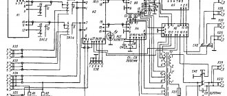
Here is a diagram of the native Amphiton filter:
There were no instruments for studying the frequency response, so I tuned it by ear. The only measurement possibility was in the filter attenuation, here:
Blue indicates the attenuation graphs of the native filter, but without speaker load. In red is my version of the filter, also without speakers. When the load (loudspeaker) is turned on, the attenuation of the filters drops, and the curves will be even steeper, plus the frequency response of the speakers themselves is also added and the final frequency response will be completely different from these graphs. Therefore, you should not pay attention to too smooth declines.
The native filter shows that the section between low and mid frequencies is about 750 Hz, mid and high frequencies – 3700 Hz. According to the new (red graphs) LF and MF - 40 Hz, MF and HF - 12000 Hz. When all speakers are turned on, the sections will be different, especially the frequency response.
The filter was adjusted in the place where the speakers will be located. I soldered wires to each speaker, and already on the couch, in a normal environment, I selected the parts. I achieved the final result after 4 months, even when the speakers were already fully assembled.
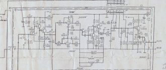
As a result, I came up with this filter:
The phase agreement of the loudspeakers is the same. At LF the second order, slightly less nominal than it was. On the midrange, first order, trimming at the bottom. Since 30 GDS does not go higher than necessary (above 5 kHz), I did not cut along the top, and the sound is more lively. Resistance to match sensitivity. At HF the second order. Everything is simple and clear. The bass coil was taken from an old filter, from the midrange section. I took the HF coil from another speaker. The capacitors were also collected from the old filter.
I used capacitors K73-11 (HF section) and MBGO (MF and LF sections). I also tried K73-17, but didn’t like the sound. All parts are glued to the floor of the speaker.
4. Replacing the suspension with a woofer
Old suspensions simply fell apart before our eyes, especially at high volumes, so repairs are required. Replacement is quite simple, remove the old suspension and glue the new one.
We clean the old suspension and everything that remains from it. I worked as a solvent worker. I worked especially carefully on the diffuser. I did not peel off the cap and the centering washer. Even without a suspension, the speaker plays as it should, without friction, but only in this position. Result:
I bought new suspensions at the radio market, $5 per pair:
Carefully! Do not smear the hangers with alcohol or solvents. The glue I used was polymer. I cleaned the gluing areas on the suspension with sandpaper. First I glued it to the diffuser, then, after drying, to the frame.
To give it a decent look, I covered the outer side of the slide with clerical ink, in 3 layers.
5. Replacement wiring
I used a regular speaker cable, 2.5 mm2 for LF, 1.5 mm2 for MF and HF. But I think that we can limit ourselves to LF – 1.5 mm2, MF and HF – 1 mm2. It will be more convenient to work with him.
I installed the usual terminals:
_
6.Improved appearance and assembly
Here the surface is leveled using putty. I removed the nameplates and aligned the holes. Here's what happened:
I cleaned the speaker covers with fine sandpaper and coated them with matte black paint from a can, in 3 layers. I bought self-adhesive to suit my taste.
Next, I covered the body and started assembling. Vatu put in what was there, did not add or take anything away. The photo shows linings for the woofers made of fiberboard. I removed the grilles in front of the speakers. Each speaker was placed on soft window insulation. Result:
_
Sample of one of the joints
Rear view, painted, because I never look back, and there is no point in covering it up.
I didn't varnish it, I painted the screw heads with black paint.
The result exceeded expectations. When installed correctly, there is full bass up to 50 Hz, then it drops off, but up to 30 Hz the pressure is still normal. The lower audible threshold is 27 Hz. The sound is natural, not annoying. Dense bass, expressive (but not protruding mids), light and clear high-frequency notes. I won’t say how much they compare to store-bought acoustics, I can only say that they sound better than they look.
When compared with the old speakers, the new version is especially distinguished by its expressive mids and light, non-hissing highs.
Another very important point. Refinement of acoustics is not the full effect of good sound. The source is also very important, a noticeable difference between a computer and a normal DVD player, not to mention CD players. A good amplifier is a big step towards good sound. Well, the correct installation. Refinement, of course, will change the sound, but the full effect cannot be achieved without a good source, amplifier and correct installation.
In the end, I want to thank my friends and participants of the Acoustic Systems forum and the Soldering Iron website, who helped in the creation of this project, thank you very much!!!
Good luck to everyone in the revision! Best regards, Dmitry!
lds 212008
25AC-027, also known as 25AC-227 and 150AC-007
Some of the most popular speakers in the USSR.
They had a lot of names with the same design.
25AC-027
AS “Electronics 25AC-227” have been produced by the Leningrad Ferropribor plant since 1985. Since 1986 were already produced under the name “Electronics 25AC-027”. At the Lviv Production Association named after. Lenin Speaker production began in 1987. called 25AS-027 and 25AS-227 Amphiton. Called 150AC-007 Amphiton (according to the short-term power of the speakers), then 150AC-007 Lort.
The price was 140 rubles (145 rubles with a stand).
Three-way speaker systems with a bass reflex “25AS-027”, “Electronics 25AS-227” are similar in design, design and parameters. For design purposes, they are made in mirror reflection.
LF head 50 GDN-3-30 (25GD-42) , MF 20 GDS-3 (15GD-11) , HF – isodynamic head 10 GI-1 .
Those. characteristics:
Recommended amplifier power: 10 – 50W Nominal input power – 25W. Maximum (nameplate) power: 50 W The nominal range of reproduced frequencies is not narrower - 31.5...31 500 Hz Frequency response unevenness, 100 - 8000 Hz: ± 4 dB Sensitivity: 86 dB Characteristic sensitivity: 0.4 Pa / √ W Nominal average sound pressure 1, 2 Pa Nominal electrical resistance – 4 Ohm. Minimum value of total electrical resistance: 3.2 Ohm Filter crossover frequency: LF/MF: 500Hz MF/HF: 3000Hz Dimensions of one speaker system 360x615x320mm Dimensions of the bass reflex: diameter 55 mm, length 165mm Tuning frequency of the bass reflex 25 - 30Hz Weight of one speaker 25 kg.
LF head 50 GDN-3-30 (25GD-42) , MF 20 GDS-3 (15GD-11) , HF – isodynamic head 10 GI-1 .
The body is made in the form of a rectangular non-separable box made of chipboard. Valuable wood veneer. The thickness of the case walls is 18 mm, the front panel, in order to increase its rigidity, is made of a 38 mm thick .
The AS 25 AS-027 uses the following set of heads: LF - 50 GDN-3-30 (25GD-42) , SCH - 20 GDS-3 (15GD-11) , manufactured by PRZ, Ivano-Frankovsk, and HF isodynamic - 10 GI-1 , manufactured in Leningrad.
The heads are framed with decorative plastic overlays: the woofer and midrange head overlays are round with 4 mounting holes; The HF head cover, which simultaneously frames the round hole of the bass reflex, is rectangular in shape. The midrange head is isolated on the inside from the total volume of the housing by a sealed plastic cap.
On the front panel of the speaker, in addition, there is a decorative nameplate with the name and main technical characteristics. The heads are protected at the front from external mechanical influences by a blackened metal mesh. The bass reflex has the following geometric dimensions: diameter 55 mm, length 165 mm, tuning frequency 25 - 30 Hz.
The internal volume of the speaker is 41 liters. To reduce the effect on the frequency response of sound pressure and the sound quality of the speaker, sound-absorbing mats - cotton wool covered with gauze - are attached to its inner walls.
Filters are mounted inside the housing on a single steel chassis to ensure separation of speaker bands. The filters provide crossover frequencies: between the LF and MF heads - 500 Hz, between the MF and HF heads - 3000 Hz .
The design of the filters uses resistors of the S5-35V type, capacitors MBG0-2, and inductors on plastic frames without cores. There is a hole on the back wall of the case through which the supply wires exit, ending with the ONTs-VI-1-2/16-V connector.
The speaker was supplied with a specially shaped stand, made of steel rod and providing, if necessary, a change in the angle of inclination of the acoustic axis.
Acustic systems
The acoustic system "35ASDS-017" was produced by Lvov Production Association named after. Lenin (PO Lort) since 1984.
The three-way dynostatic acoustic system with a bass reflex "35ASDS-017" provides high-quality reproduction of sound programs complete with high-quality household radio-electronic equipment. AC provides high sound purity, does not tire the listener, and creates a good stereo effect and presence effect. In the acoustic system, electrostatic loudspeaker heads (HF and MF, 2 pcs. each) are used as high-frequency and mid-frequency links, characterized by very low transient, phase, frequency and nonlinear distortions; The dynamic head of the loudspeaker type “75 GDN-3” is used as a low-frequency link; there is a smooth high-frequency tone control, which allows you to adjust the timbre coloring of the sound of the acoustic system within certain limits (5 dB).
Specifications:
- Maximum noise power of speakers is 50 W.
- The range of reproduced frequencies is 25...25000 Hz.
- Average sound pressure at rated power is 1.77 Pa.
- The nominal impedance of the speaker is 4 ohms.
- Power consumption - 8 W.
- Dimensions - 360x1070x380 mm.
- Weight - 30 kg.
Design Features
The 35ASDS-017 acoustic system is made in the form of two blocks structurally connected to each other - low-frequency and mid-high-frequency. The body of the low-frequency unit is made in the form of a rectangular non-demountable box made of chipboard, veneered with valuable wood veneer. The thickness of the case walls is 18 mm; the front panel, in order to increase its rigidity, is made of a 38 mm thick plate. The 75GDN-Z head, manufactured by PRZ, Ivano-Frankovsk and installed on the front panel of the case, is used as a low-frequency electrodynamic link in the 35ASDS-017. The head is framed by a decorative ring-shaped trim with four fastening lugs made of coated plastic. On the front panel of the low-frequency block housing, in addition to the head, there is a 70 mm bass reflex hole - the outlet of a plastic pipe 180 mm long. The geometric dimensions of the bass reflex determine its setting at a frequency of 25 - 30 Hz.
The internal volume of the low-frequency unit is 45 liters. To reduce the impact on the frequency response of sound pressure and the sound quality of speakers from the resonances of the internal volume of the housing, the latter is filled with a sound absorber, which is mats of technical wool, covered with gauze, evenly spaced and fixed to the internal walls of the housing. An electric filter is mounted inside the low-frequency unit housing on a steel chassis, providing electrical separation of the low-frequency speaker band from the mid- and high-frequency ones.
The basic electrical circuit of the filter makes it possible to obtain a frequency response decline in the mid-frequency region of 6 dB per octave and a crossover frequency of 500 Hz.
The mid- and high-frequency unit consists of two parts - the power supply and the mid- and high-frequency emitters themselves. Two mid-frequency and two high-frequency electrostatic emitters are mounted on a flat frame mounted on the power supply. Each of the emitters is a thin (5 µm thick) metallized lavsan film stretched between two perforated plates (electrodes) made of foil-clad fiberglass laminate of the SF1-35 grade, coated with 200 µm thick UR231 varnish to prevent electrical breakdown with a high polarizing voltage. The polarizing voltage creates a uniform electrostatic voltage between the plates, in which the thin film oscillates (when an electric signal of audio frequency is passed through). Hermetic dimensions of each emitter: mid-frequency 185x165 mm, high-frequency 65x165 mm.
The power supply housing on the board contains:
- a polarizer that provides a constant polarizing voltage for the high-frequency emitter - 1.1 kV, for the mid-frequency emitter 2.2 kV;
- two transformers providing the supply of an electrical audio signal to the mid- and high-frequency emitters, and at the same time the electrical separation of the mid- and high-frequency bands of the speakers;
- the mid-frequency bandpass transformer has a transformation ratio of 240, and the high-frequency band transformer has 160. The crossover frequency between these bands is 4000 Hz;
- network transformer providing power supply from an alternating voltage network of 50 Hz, 220 V to the polarizer. Electrical power consumption is no more than 8 W.
On the front panel of the power supply there are:
- power button with ON indicator;
- knob for smoothly adjusting the level of high frequencies HF TIMBER, allowing for the rise and fall of the frequency response of sound pressure from 4 kHz within ±3 dB from the NORM position.
In addition, there is a decorative nameplate on the front panel indicating the name of the speaker and its main technical characteristics.
The front panels of the low- and mid-high-frequency units, as well as the back of the mid-high-frequency unit, are covered with frames with decorative radio fabric.
On the back wall of the speaker unit's LF housing there are special terminals that allow you to connect supply wires to the speakers.
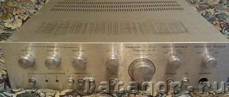
Big black Amphiton-A1-01
UMZCH Amfiton-A1-01. A review from the “broken by hand” category. Designed for enthusiastic radio amateurs. There are few interesting photos, but a lot of tediousness. 1.
By the will of fate, and it couldn’t be otherwise, on December 5, 2022, a large black dirty amplifier Amphiton-A1-01 fell into my hands. The secret of his adventures, naturally, is unknown. More or less complete information about this amplifier is on the page. Main technical characteristics from the manufacturer: Reproducible frequency range: 20 - 20000 Hz Frequency response unevenness in the range 20-20000 Hz: ±1.5 dB Connected speaker impedances: 4 Ohms Rated power: 20 W at 4 Ohms Nonlinear distortion coefficient: 0.3% Harmonic distortion in the range 40-12500 Hz: 0.3% Total intermodulation distortion: 0.6%
I received the amplifier in a non-working state:
I removed the top cover: all components are in place; wires cut with wire cutters are not visible. Curiosity got the better of me: I plugged it into the socket and pressed the power button: the transformer hummed intensely, and smoke came out from the output amplifiers. I unplugged the cord from the socket and began disassembling it.
2.
Why all this fuss with a non-working amplifier: - hobby - get a donor case + radiators to build a JLH 1969 amplifier - revive the channels of the output (final) power amplifier, take measurements of interest, listen a little and... take it apart - write a review on Mysku
It should be explained why the task was not to restore the amplifier. The design of the amplifier is very inconvenient: in order to remove the radiators with the channel boards attached to them from the case, I had to disassemble half of the amplifier (to get to some fastening screws), unsolder the input circuits and cut off all the other wires suitable for the boards with side cutters. Why cut everything? Yes, because otherwise it will not be possible to restore the channels: it is impossible to get to the PA boards installed in the case either with probes or a soldering iron.
Secondly, there is neither the desire nor the time to restore and check all other components of the amplifier. Plus, they are of no interest: there are no tone and balance adjustments in a home setup as a class.
Note: in the setup, switching and volume control is provided by a device based on a specialized TI PGA2311 chip
The PGA2311 is hidden in an unnamed device:
3.
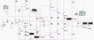
Restoration of PA channels. Scheme:
The supply voltage, according to real measurements, is +-30 V.
Here are the final PA boards after being removed from the case:
Burnt emitter resistors:
And capacitors on which the year of manufacture “1983” is visible. The nameplate on the amplifier says 1984.
List of parts that were replaced: - electrolytic capacitors C2 and C6 - powerful transistors (on KT818GM and KT819GM) - emitter resistors R32 and R33
Elements removed: — R3 and R8 (zero balancing, more on that below); — VD9, VD10, R26, R27 (i.e. abolished current protection, still did not save the channels from burnout).
The rest of the semiconductors and some blackened resistors were surprisingly intact.
4.
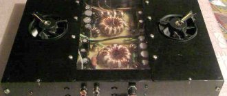
Amphiton-A1-01 amplifier power supply. The build quality of the transformer is poor.
Plus a link to the video. It doesn't buzz very loudly and even works. Good for experimentation.
But this monstrosity (a diode bridge of four KD202 diodes on the protection board) powered the entire amplifier:
It was cut out with side cutters and thrown into the abyss.
To power the test bench, I assembled a BR610 bridge and a pair of 10,000 uF*63V capacitors on wires:
5.
Pathologies found in the diagram. Blunder No. 1. Zero balancing at the PA output is provided by elements R3, R4, R5, R6, R8, C8. This balancing works clumsily: either the electrolyte C8 began to leak, or the contact of the tuning resistor R6 was poor, but a strange bumpiness was observed at the output of each channel. Therefore, both in this Amfiton-A1-01 scheme and in the Amfiton-U-101M scheme these elements were removed. Without them, the output of the PA channels turned out to be within 30 mV without chatter. IMHO, it's fine.
Normally, an integrator (operational amplifier) is installed, and at the output we immediately have a bias within a few millivolts. Cheap and reliable.
Blunder No. 2. Current source (IST) on transistor VT8. The actual value of the IST current is about 6 mA (voltage drop 0.75V across R19=120 Ohm). When powering the circuit +-30 V, the power on the VT8 collector is 0.19 W
!
For the TO-92 case (in the USSR this type of case was designated KT-26), the power of 0.2 W is a clear excess. A typical junction-to-ambient thermal resistance for a TO-92 package is 200 K/W. Transition temperature T = 40°C + 0.2W * 200K/W = 80 (°C) +40°C is the temperature in a closed amplifier case, provided that +30°C in the apartment. Why be surprised?
In our area, outside in the shade it can be almost +42°C
And in the apartment with the air conditioner running +28..30 °C.
They did not reach the maximum transition temperature of 125 °C. Under normal household conditions, boards are covered with a layer of dust or pet fur. Plus a closed housing and no forced airflow. After which the thermal conditions inside the case change in the most unpredictable way. And if a caring user covers the amplifier with a beautiful patterned cloth (so that dust does not get inside) or piles other components on top, then... Undoubtedly, the serial amplifiers worked, but in other similar circuits in IST with a heat dissipation of >0.15 W, the developers installed more powerful transistors (KT815 , KT817).
A true story from my work.
The chief engineer of the research and development enterprise where I worked in the 90s had the habit of walking around laboratories at the beginning of each working day, asking questions to the developers, issuing instructions, etc. On my desktop there was a prototype working chip of a 4-channel pneumatic-electric converter (0-100 kPa -> 4-20 mA). The IST had the usual KT817G, simply soldered into the board, i.e. without any radiators. The power on each KT817G is 0.25 W. If you touched them with your fingers, they were noticeably hot.
That's what the chief engineer did: he touched it. (Part of the text was removed by censorship.) After which I was given an enema and given a control center to immediately install the transistors in the TO-220 housing, because there was simply no room on the board to add heatsinks. And the first batch of boards for the devices was already ready in the warehouse.
After this incident, they giggled for a long time about how the chief engineer received a “burn” from a quarter watt. )))
For the purity of the experiment, I left the IST unchanged. Naturally, this error has been corrected in the Amphiton-U-101M design. )
Blunder No. 3. Lack of fuses in the power supply circuits of the final amplifiers. When breaking through the output transistors, the current (from the +30V line to the -30V line) flows almost without limitation. What this leads to, look at the photo above. Saved on fuses. (
Blunder No. 4. Why did the current protection (VT10 and VT11 with wiring) not save the circuit from burnout? It's simple. Due to the fact that the “optimizers” raised the supply voltage of the channels from +-22.5V to +-30V and instead of KT818-819 in TO-3 packages they installed a “light version” in TO-220 packages, the transistors simply suffered a thermal breakdown. Let's look at the directory:
We calculate: peak power at the collector with a complex load of 3 Ohms Pk = 0.5 * (30*30 / 3 Ohms) = 150 W That’s it, the transistors are finished.
Blunder No. 5. Power supply capacitors for the terminal PA. This is where savings are at their finest. A pair of 2200 uF*63 electrolytes on each PA board. Those. a total of 4400 µF for the positive polarity and 4400 µF for the negative polarity. No comments.
6.
Then everything is as usual. Photos from the workplace:
On the left you can see the lamp protection housing.
Test bench with two channels installed:
7.
Measurements and listening. PA output (transient process when turned on):
Acceptable.
Harmonic coefficient (HC) without load:
With 4 ohm load:
Harmonic distortion (HHD) without load: With 4 ohm load:
To be honest, I don’t know why there was a fourfold spread in Kg between channels. The UM honestly met the 0.3% declared by the manufacturer.
Slew rate of output voltage without load:
With 4 ohm load:
In both cases, 5 V/μs, which was determined in the simulation program for the Amfiton-U-101 amplifier (the same 5 V/μs):
Now, to listen to the restored PA channels, there are only two ways: 1) push them back into the case, soldering the conductors and swearing obscenely; 2) leave the restored PA channels on the test bench and listen in this form.
As a reasonable and lazy person, I chose option No. 2. ))
The shelf (at the bottom is the lower part of the amplifier case with the power supply, at the top is the test stand) was moved closer to the setup and installed on two stools.
The audition took place on December 7, 2020, with a minimum number of “listeners” (only two). Subjectively, the Amfiton-A1-01 amplifier is the most common UMZCH, as well as its factory brothers Amfiton-U-101 and Amfiton-U-002. I think it’s all to blame for the frequency correction, performed with a margin. Therefore, the slew rate is only 5 V/µs. In the low-frequency area, the situation has improved (after all, there are a couple of brand new 10,000 µF in the power supply).
8.
The area of radiators in UMZCH Amfiton-U-101 and Amfiton-A1-01. There is an opinion that everything is on the Internet. Don't believe it. © I needed to somehow find data on the radiators of the Odyssey-010 amplifier: I couldn’t find it. Photos of radiators from UMZCH Amfiton-A1-01:
Characteristics: - dimensions 270*80*25 mm - ribs height 18 mm - base thickness 7 mm - total area 1160 sq. cm
Formulas for calculating radiator area:
9.
Conclusions: UMZCH Amfiton-A1-01 is a typical product of the electronics industry of the former USSR.
Corresponds to the declared characteristics. Sound-wise, nothing outstanding.
For 15-20 euros we get a set of spare parts for an experienced radio amateur: housing, radiators, printed circuit boards, some radio components. And a transformer, with the hum of which you can fight.
To get a more interesting sound, it is not enough to simply replace the electrolytes in an old amplifier with new ones. It will be necessary to either completely rework the circuit, or even replace the PA with another one whose sound has reliable information.
About other people's opinions.
PR for TDA7294 began when the Internet had not yet arrived in our homes. Reviews about this chip are only positive. After reading laudatory reviews, my colleague, whose company was listening to the Amphiton-A1-01, got lazy and assembled an amplifier using the TDA7294. A dream for lazy people: PP 5*5cm, microcircuit and a pinch of strapping. The two of us listened to the freshly assembled amplifier. Based on the results of joint listening, the TDA7294 chip was recognized as having been blacklisted once and for all. And the story became indicative for the two of us. So be careful when listening to other people's opinions.
Only measuring instruments do not lie.
Happy experiments and launches of amplifiers to everyone.