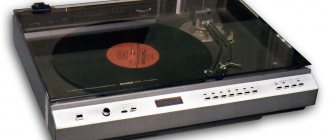
I'll show you with a real example what you can do with old speakers, namely their drivers, to get improved sound.
It happened, I found old speakers in the garage called Mayak 15AS-222, people simply called them “Cubes”. They stood idle for at least 10 years. The case began to swell in the corners due to moisture, and the foam rubber hangers turned into mush under light pressure. The sound of the speakers was not very good, although they had some potential. They mumbled very loudly at low frequencies, sometimes they resonated and emitted a hum.
Now they bear little resemblance to those “Cubes” that were lying around in the garage, both in appearance and in sound.
↑ We improve speakers 10 GDSh-1-4 (10 GD-36K)
Let's start improving the speaker. For a very long time I collected a lot of information from different sources on improving speakers, a lot of debates and discussions of different technologies, and in the end I found something. Here's the speaker itself. The suspension in this one is still beautiful, but in the second speaker it broke after listening in the test box.
Next you need to do an extensive amputation of the old suspension. In a barbaric manner, we rip the suspension out of the speaker. On the left you can see what it has become. If you take that pile of sawdust and squeeze it in your hand, it will stick together into a homogeneous mass.
A beautiful new pendant, bought at the radio market.
To stick it on, I first coated the basket and diffuser with “88” glue, then carefully soaked the foam hanger. It was difficult to glue; after applying glue, it began to ripple along the inner and outer edges, but in the end it stuck on somehow. Facial transformation.
There were also rubber surrounds on sale; they are more suitable for woofers. You can also order fabric pendants by Peter Zodniev.
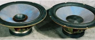
Magnets are next. Here you can see a small, not very powerful ferrite magnet. I didn’t find books on designing dynamic heads, but I read on the Internet how it works and the principle of its operation. Modern expensive speakers are made with neodymium magnets, which are almost 10 times more powerful for the same volume.
As far as I understand, the size of the magnet is more determined by its cost in production; therefore, if you find a neodymium magnet of the same size, the induction force of the coil will be much higher, and accordingly the sensitivity of the speaker will increase. The high-frequency vibrations of the speaker will become more “responsive”, and in general all this will only be beneficial. But where can you find such a magnet, and how much will it cost?
There is an exit. This is approximately the same size magnet, found on the radio market.
You need to glue in antiphase (so that they repel). I glued it to what I had, namely liquid nails. I can’t make a comparison of the sound before and after, because I didn’t take measurements, but I like what’s playing now while I’m writing this article. I think it made at least some contribution to the sound quality.
Moving wires tend to bend at soldering points. This is a copper braid with a bundle of threads inside. They slowly began to break from the fastening side of the basket. It was decided to tear them off and replace them with MGTF wire.
The MGTF wire is very well suited for such purposes. It is very resistant to frequent kinking, and the cone is known to wobble a lot, especially in piston mode, up to 200 Hz.
To increase the maximum transmitted power, reduce wire resistance and increase resistance to bending, a simple braid was woven.
After soldering the wires, they need to be glued to the diffuser, because the weakest point where the wire breaks is the place near the solder, like the place where the stationary section of the wire transitions to the movable one. You can also stupidly sew the wire with threads to the diffuser, but this is a matter of taste.
Again I glued it to what was there. Liquid Nails.
Next comes the thing that can cause bleeding in the brain. This is my implementation of PAS (Acoustic Impedance Panel). If you've ever taken apart headphones, you've seen something similar on the speakers. There were proposals to cover everything with padding polyester, which is not very suitable for damping, or with cotton wool, which delaminates, a piece will fall on the diffuser and rustle.
This piece of some material was taken from a bag, the purpose of which I do not know. Very elastic material and possibly perforated. Rather, there are not holes there, but pressed squares. The material is soft, allows air to pass through normally, creating light resistance. The reason for choosing this material is also to protect the diffuser from dust or pieces of damping material from inside the speaker.
The purpose of this PAS is to reduce air vibrations even at the level of the basket. Passing through the fabric, the air will rub against its structure, thereby losing its strength. The material is elastically stretched, so there will be no resonance or flapping. Audiophiles say that this method of speaker damping has a positive effect on its quality factor and resonant frequency. I did not take measurements before or after. I like the final result, I have no complaints about the sound.
These are the cool tablecloth speakers I have. This is what I call modification - a useful improvement of something while maintaining/improving its properties and appearance.
I made the next video to celebrate what I heard from these “sucky” speakers. If you mentally turn on the frequency response corrector in your brain and listen, you can hear how cool the speaker works. The amplifier is operated by a Samsung DVD player with an AUX input. The box with the speaker is used as a subwoofer, and Radiotehnika S-30 is used as satellites. The test box is assembled using liquid nails and an unreal number of screws, and inside there are 2 large spacers to dampen resonances.
[media=https://www.youtube.com/watch?v=J36-jiRFSMU]
Refinement of AC S-90 (4 Ohms). Report 25 years later.
On any forum you can come across a topic a la “remaking the S-90”. For some reason there is no such topic on Mysku. We need to correct the situation. — So in the USSR there was a whole institute of acoustics. — There was an institute, but there was no good acoustics... © 1.
A little copy-paste.
AC
on sale that look similar to the S-90, but they are indecently expensive.
There are other good Soviet speakers that are much better than the S-90, but getting them, especially in good condition, is more difficult, and they will cost even more. And there are Chinese speakers (they may have a brand name and a beautiful nameplate, but the essence remains) that are sold in DNS, Eldorado, M.Video, Comfy, Foxtrot, etc. So, if the choice is between Chinese speakers from these stores and the S-90, you should take the S-90. Anything would be better than throwing money down the drain and putting maybe beautiful, but dull Chinese speakers next to the LCD TV, imitating an expensive stereo system. If the current speakers are generally satisfactory, but money is tight, it’s better not to spend it. The fact is that you won’t find real happiness from buying an S-90. If you have enough money, then you can immediately step over this step and buy something good. But if built-in or budget audio systems are not satisfactory and you have an irresistible desire to tinker with a soldering iron, then go ahead and sing. About buying a used S-90 speaker
On OLH, Avito and other Internet sites, the average price for a pair is 7-10,000 rubles, on radio markets and from hucksters - 13-15,000 rubles. (from 1000 UAH in Ukraine). Don't forget that you will also need to buy an amplifier for these speakers. Although a situation is possible when, in a radio market pavilion littered with Soviet junk, a mustachioed old man with a sly face, who imagines himself to be a great connoisseur of warm tube sound, will break 17 thousand or more. And a reasonable remark that these speakers don’t cost that much will be taken as a personal insult. Conversations with such aesthetes are short. In small towns and villages, you can get a subject at the market for pennies or in a neighbor’s garage for a bottle, so the speakers are the undisputed leader in the (average) quality/price (generally meager) category. But in large cities, the likelihood of a freebie is extremely small, since people have long figured out the trick and are counting on making a big profit on lovers of the now fashionable vintage. In addition, resellers do not sleep and all profitable offers immediately go to them, and then are resold with a double or even triple markup.
Known disadvantages of the S-90 speaker: 1. HF speaker. 2. Megabass (it’s strange why this was considered a disadvantage). 3. Internal wiring with thin wires. 4. Disgusting midrange. We look at the magazine “Radio” No. 8 for 1987 and No. 5 for 1995. 5. Bubbling at low frequencies - the volume of the housing is too small for a low-frequency driver (you just need to recalculate the FI). 6. Although the grilles on the speakers protect the paper cones from children, they only introduce negative effects into the sound (true for the grilles of the woofers). 7. Weak damping of the rear wall (it is enough to tap the walls of the speaker to make sure of this). 8. Significant resistance of the low-pass filter coil (0.6 Ohm), which is why there is insufficient damping of the woofer (and the housing was blamed for everything).
2.
Factory diagram of AC S-90.
The Multisim 10 simulation program perfectly calculates all kinds of filters, even starting with early versions of EWB512. Therefore, it would be a sin not to use it. To simplify the dynamics, they have been replaced with active loads of 4 Ohms, 8 Ohms and 16 Ohms:
Polarity inversion Gr.3 is taken into account in adder A1.
Here is the frequency response:
and FCHH
With real speakers, naturally, the graphs change for the worse.
After looking at these pictures, I was a little stunned and went to leaf through Radio magazines in search of a solution to this issue.
3.
Modification of 35AS-015 based on a ladder filter (Radio 1990 No. 04 p. 57). A long-known solution from an author from Dnepropetrovsk. The article has been copied by all and sundry, but there are no real reviews to be seen. Reminds me of a joke: People, who bought climbing equipment on Ali? There don't seem to be any bad reviews. ))
Scheme:
The author states: “... The modified speaker “Electronics” 35AC-015 uses the so-called ladder filter of the all-passing type of the sixth order.... They simultaneously satisfy several requirements: - provide a flat total frequency response in voltage - symmetrical directivity characteristics of the speaker in the range of filter separation frequencies - small level of phase distortion - filters are least sensitive to changes in the values of their constituent elements" ©
The last point, of course, makes you smile: why then do you need high-precision coils in the circuit? The higher the order of the filter, the more accurate the values must be. Otherwise, the filter simply will not work properly.
With the advent of EWB512 and similar programs, any schoolchild can calculate a 6th order filter. And in the distant 60s, 70s and even 80s, candidates of mathematical sciences were engaged in filter calculations.
Turn on Multisim 10, look:
Frequency response:
FCHH:
Hmm, “low level of phase distortion” in all its glory. )
After looking at the pictures, the desire to repeat the scheme disappeared. And winding reels with an accuracy of 0.1% is a debatable pleasure. Even if the author writes “When assessing the sound quality of converted speakers, all listeners are concerned about the sound.”
The shadow of doubt (whether someone even assembled the diagram) does not leave me even now.
4.
What else is interesting about modeling AC filters? A very thorough article: The problem of frequency separation of signals in acoustic systems. This is the best I've come across. But this is today, and 25 years ago I didn’t have the Internet.
5.
How can you convert your S-90s without making a mess? There was almost nothing available. There were some capacitors. And there are many more K73-17 1 µF and 2.2 µF. Wire f0.7mm and f1mm a little.
Instruments - to a minimum: - DT830B multimeter - homemade generator 20 Hz-20 kHz - LC meter of unknown breed was borrowed (not stolen! just borrowed) at work, accuracy 2.5%; — oscilloscope S1-49 (used as a frequency meter, since there is just a twist on the generator); There was no personal computer, much less a measuring microphone, at home. (It was with such introductory notes that I had to start.
The original AC filters were removed. I decided not to disassemble them, because... No one gave any guarantees that the result of the rework would be satisfactory. It was necessary to leave a path for retreat.
6.
Set of speakers in S-90. The option “throw everything away and buy new imported ones” was not considered for obvious reasons.
Woofer - 75 GDN-1-4 (30 GD-2)
There were no complaints against him. I just had to remove the protective metal grill to prevent it from ringing. But the frame covering the edges of the grill and the basket remains.
Midrange speaker - 20 GDS-1-8 (15 GD-11) During a test run of the speaker, a crocodile resonant (?) bump emerges from the generator in the range of 4.5 kHz (i.e., at a frequency near the maximum sensitivity of hearing). But there is no “crocodile” on the frequency response:
I don’t accept engaging in obscurantism (covering a basket with rags, filling the space behind the diffuser with cotton wool, smearing the blood of virgins with something unknown on the pendants, etc.). “Not our method!” ©
In short, the midrange speakers are trash. Exactly like this: Due to the strange resonance of the midrange speakers - the specific sound of the S-90 speakers.
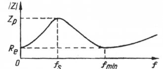
HF speaker - 6 GDV-6-16 (10 GD-35) Main resonance frequency: 2900 – 3600 Hz. Evil tongues claim that the reason for the poor sound of the S-90 is precisely because of the HF speakers.
Personally, I don’t sneeze at any unverified opinions. We take a generator, a PA, connect speaker 10 GD-35 and listen at low power. Along the way, we turn the frequency adjustment from 1 kHz up the range. The frequency of the main resonance is easily determined by ear, everything corresponds to the passport data.
Further up the frequencies: no surprises up to the maximum audible frequency. I checked both tweeters: everything is OK.
I left the protective grilles for the midrange and tweeters as is, because... I couldn’t “knock out” the parasitic overtones from them.
7.
Replacing midrange speakers.
As usual, there were some tricks of fortune. Two people (me and a work colleague) were sent to Kharkov for some kind of exhibition (industrial devices, automation of chemical production). The train arrived around 6 am, and before the start of the exhibition there was still time to stop by the Kharkov radio market. 20GDSH-101
midrange speakers were purchased in the amount of 6 pieces (one pair for an employee, the rest for me). With this extra weight we visited the exhibition, where we collected several more kilos of advertising brochures from free flash drives.
Upon arrival home, the midrange speaker was checked from the generator to make sure there were no “crocodiles”. No surprises, everything is fine. ))
Now, I remember. Later there was another purchase of 20GDSh-101 (4 pieces) for a project that never took place.
Where the speakers went: - 1st pair in my S-90 - 2nd pair in 35AC-015 - 3rd pair in another S-90 (2005; it was in the 3rd pair that the FI was re-read when using the program JBL). - 4th pair - in 25AS-132 Electronics (they were destroyed by a child because there were no protective grilles) - 5th pair - found in a storage room, having lain for 25 years
The Internet doesn’t really know anything about them. There is only fragmentary information about this model. It is mentioned that this is an analogue of 5 GDSh-5-8.
Note: 25AS-132 Electronics is a clone of 50AS-107 Electronics, produced since 1987 at the Severodonetsk Resistance Plant.
8.
Circuits that were considered lost: An auxiliary adder and an inverter are assembled on the operational amplifier, simulating an inverted connection of a high-frequency speaker.
Why are there differences in the schemes? I do not remember.
9.
Filters. The filter calculations were done in the EWB512 simulator using the same simplified method as in the examples above. All the ideas - it couldn’t be simpler: - give the woofer the range that it normally reproduces (up to 500-600 Hz) - 1st order low-pass filter (and there are fewer parts, and the accuracy of the coil winding is not critical) - give the midrange speaker everything from 500- 600 Hz and higher to frequencies that it normally reproduces (i.e. up to 8-10 kHz) - bandpass filter for the midrange speaker - also 1st order (for the same reasons) - give the tweeter everything above 8-10 kHz — filter for the high-frequency speaker — 2nd order (task: to obtain the maximum possible attenuation of the signal at the main resonance frequency) — to obtain the total frequency response as smooth as possible
The low-pass filter coil that took part in the prototyping of the circuit has been preserved:
Wire f0.7mm. The resistance is about 0.2 mm (in the diagram from the archive you can see 0.2 Ohm - this is the active resistance of the low-pass filter coil). When the coils were wound with 1mm wire, the resistance decreased by 2 times (i.e. 0.1 Ohm). Resistance of the low-pass filter coil from S-90 (still stored in the closet) 0.6 Ohm
Due to the reduction in coil resistance by 6 times, the damping of the woofer, of course, has improved. As a result, the low-frequency muttering went away. Naturally, the UMZCH and cables to the speakers are also responsible for damping, not least.
10.
And again Multisim. Final outline:
R1, R3, R4 - LF, MF, HF speakers, respectively. Frequency response:
FCHH:
Much smoother than I have seen with other schemes. ))
“The ideal phase response of any filter, including a separation filter, could be considered zero (no time delay) or linearly increasing (constant delay at all frequencies). Among those filters that can be used as separation filters, only the 1st order filter has an ideal phase response. As a result, the shape of a signal passed through an speaker with 1st order crossover filters has a better chance of remaining undistorted than, say, with 3rd order filters. However, it is clear that solving the main problem - filtering and frequency division - with filters of such a small order is difficult.
Group delay is also a frequency characteristic, representing the derivative of the phase response with respect to frequency as a function, again, of frequency. Sharp group delay fluctuations indicate the possibility of different delays of components of a real signal having different frequencies: the signal will distort its shape, as acousticians say, “scatter”. The drum will no longer be a drum, pizzicato will no longer be pizzicato.” ©
The concept has been realized. A linearly increasing phase response was obtained.
Low pass filter (LPF). -3 dB bandwidth up to 640 Hz: midrange filter. Bandwidth approximately 600 Hz to 5 kHz:
High-pass filter (HPF). Attenuation at the main resonance frequency of the high-frequency speaker -21 dB: High-frequency passband at the level of -3 dB (from -0.5 to 20 kHz) from 10 kHz:
11.
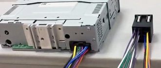
And so, there is a scheme. Anyone can convert their S-90s. Sequence of alteration: 1. Unscrew the speakers, remove the filters. 2. Wind the coils using an LC meter (filter coils for midrange and high-frequency speakers can be obtained by unwinding turns L2 and L4; you can also wind L1 up to 1 mH, it’s up to you to decide). 3. Assemble (solder) the filters and install them in the speaker housings. 4. Install the speakers (on a thin layer of plumbing sealant). 5. (Optional) replace the connectors for connecting cables to the speakers with something modern:
6. (Optional) cover the rear wall of the speaker with a vibration-absorbing coating. 7. The cross-section of wires for installation inside is not necessarily 4 sq. mm, you can limit yourself to 1.5 sq. mm. mm.
12. An important point during assembly.
When soldering the wires to the HF speaker, the question arose, where are the “+” and “-” on the markings. There is no need to guess or make notes with a marker when dismantling the speaker (during assembly, the wires could simply be soldered “from the bulldozer”). The “at random” or “50/50” rule will not help here.
When the filter board is assembled, you need to connect the midrange speaker (to the filter), observing the polarity.
The tweeter speaker should be connected to the high-frequency filter via a double microphone (or similar toggle switch): This is required to quickly change the polarity when connecting the tweeter speaker.
Next, the midrange speaker (with a plastic “glass”) and the tweeter should be placed side by side in the same plane. And turn on any musical composition containing enough high frequency. When you press a button, you can hear the difference immediately. Then you can use a marker to put a bold dot on the tweeter. )) “And be careful not to mix it up, Kutuzov!” ©
13.
Measurements with a measuring microphone of converted S-90s.
Harmonic coefficient (these are harmonics of 20GDSH-101 and from UM - all together; from whichever is greater - fz):
14.
End of story. Photos of my S-90 in 2015 shortly before the sale:
The protective grilles were installed back in 2006 after the birth of my son. After 2006 The speakers were used little and were sent to a new owner in 2015. Yes, I sometimes regret selling the S-90. Should have been left for experimentation. But the past cannot be returned...
I wish everyone to use only proven schemes and solutions!
Update dated 02/13/2021. The volume of the plastic “glass” for the midrange speaker of the S-90 speaker is 1.82 liters. The measurement is made by filling a glass with water and then emptying it with a measuring cup.
↑ New speaker enclosures in the “ZYa” format
I won’t talk much about the manufacture of cases. I chose ZY because I liked the sound, namely the absence of subwoofer hum. I’ll just show you the finished speakers with these speakers and a drawing for the housing with cutting out an OSB board of 2500×1250×22 mm format.
Metal meshes from old speakers also came into use after child parasites damaged the HF horn.↑ Total
I have never heard such a good sound.
The mids and upper mids play simply amazing! There are not many and not few high frequencies. To be honest, I’m surprised that a broadband speaker produces high frequencies of such quality, and in general, plays so cleanly. Well, low frequencies are something. The bass is so deep that it gets under your skin, and if you turn it up loud, your chest begins to resonate.
These speakers sound better than my Audio-Technica ATH-M30 headphones. If the situation allows, I would rather listen to speakers than headphones.
Thank you all for your attention!
2-way speakers (pair 4 GD-35 + 4 GDSH-3-8)
These speakers had a prototype in the form of rare, but not bad-sounding speakers from the Rigonda-stereo radio. It was decided not to make side ovals, since the room is filled with furniture and there is no room for sound emission to the side. Initially, the idea was discussed of simply supplementing 4 GD-35s with an oval tweeter 2 GD-36s, but I dissuaded the speaker customer from this idea, because Due to the variation in parameters, not every 2 GD-36 will do, and to select a good pair you will have to sift through quite a few of these heads. In addition, 4 GD-35, due to its design features, does not have a sufficiently expressive, dull sound in the midrange, that is, where the tweeter is not allowed to go. Meanwhile, the Soviet industry produced several good models of SB heads that had excellent sound in the mid/high frequency range. So the decision to abandon the tweeter and replace it with a silent speaker is completely justified. Initially, Ovalnik 2 GD-38 was planned for this role (the drawings were made specifically for this head), but unexpectedly, I came across speakers from a Vega-335 radio tape recorder, with only 4 GDSH-3-8 inside, after listening to which, I was extremely impressed with their sound.
Frequency response measurements confirmed what was heard. The smoothest frequency response, up to 10 kHz, followed by a smooth decline. Excellent, clear mid and high frequencies with high sound resolution. In addition, the round speaker, in my opinion, looks more organic on the panel. It was decided to opt for 4 GDSh-3-8.
The internal proportions of the buildings correspond to the rules of the golden section. The depth of the case inside is 250 mm. Since the speakers have an open design, there is no point in making the walls thick; no pressure is created inside. Plywood 12 mm thick is quite suitable material! The ends of the sidewalls were milled at an angle of 45°. For gluing, professional PVA glue D3 and tape clamps were used.
For the exterior finishing, fine-line “walnut” veneer on a non-woven backing was chosen. It is convenient to work with him, because... it does not crumble and is produced in sheets of 2.5 x 0.65 m, which makes it possible to do without jointing the knolls. For gluing veneer, I use Alcor ATS 440PH adhesive. This is a polychloroprene contact adhesive. You can get it at shoe repair shops.
The final finishing was done with tung oil in 2 times. Environmentally friendly material with an extremely weak, pleasant odor. After drying for 2 days, the surface is polished with a lint-free cloth and acquires a silky shine.
The grills are made of 10 mm thick MDF and covered with sound-transparent fabric. First, the MDF is chamfered using a manual milling cutter. Unfortunately, I don't remember the name of the fabric, but it came from a simple craft store. The fabric is folded over and glued on the reverse side.
Mixing the filters didn't take much time. The speakers organically complement each other. 4 GD-35 are connected in series and have a total resistance of 8 ohms. The filter circuit is simple: pair 4 GD-35 is connected through a 1.35 mH inductor, and 4 GDSh-3-8 through a 4.7 μF capacitor. No extras. No resistors were needed to equalize sensitivity. The speakers have high sound resolution and perfectly convey the atmosphere of the recording. Voices and instruments sound natural and alive.
Depending on the environment, you can adjust the sound by adding a certain amount of sound-absorbing material inside (sintepon, batting, etc.). This is especially true when the back of the speaker is close to the wall.
Author of the work: Alexander Lukin , Omsk