An audio amplifier is a device where the signal passes through series-connected stages. Troubleshooting is carried out using a fairly simple algorithm, so the question of how to repair an audio amplifier with your own hands is not too difficult. The only condition is the availability of measuring equipment. A conventional tester can detect some defects, and the presence of measuring equipment such as an oscilloscope and an audio frequency generator will allow you to repair the device efficiently and quickly.
How to fix an audio amplifier
Troubleshooting low frequency amplification systems must be performed in a specific sequence. This will avoid mistakes and waste of time. Repair of an audio amplifier begins with an external inspection. In this case, you can easily notice torn wires, broken conductors or mechanical damage to individual elements. Since all parts of the sound system that are exposed to too much current change, inspection will reveal defects associated with electrical damage in various circuits. On permanent resistors, the paint completely burns off, and the printed tracks on the board are often damaged. Defective electrolytic capacitors can be easily detected by swelling in the upper part of the cylindrical housing. Typically, such damage to radio components is not a cause, but a consequence of another malfunction, therefore, after eliminating visible defects, it is not recommended to turn on the device, but all cascades should be checked sequentially. The first thing you can do is ring the speaker system and check for an open circuit between the amplifier output and the speakers.
| Name of service | Price |
| Repair of monoblock amplifiers from 500W | from 2000 |
| Repair of monoblock amplifiers from 800W | from 2500 |
| Repair of monoblock amplifiers from 1000W | from 3000 |
| Repair of monoblock amplifiers from 1200W | from 3500 |
| Repair of monoblock amplifiers from 2000W and above | from 4500 |
| Repair of two/four channel amplifiers from 100w | from 1000 |
| Repair of two/four channel amplifiers from 200w | from 1500 |
| Repair of two/four channel amplifiers from 400w | from 2000 |
| Repair of two/four channel amplifiers from 500w and above | from 3500 |
| Repair of five channel amplifiers | from 2300 |
| Prevention of car amplifiers | 1100 |
| Amplifier tuning (making improvements, increasing power) | from 1500 |
| Minor repairs | 1000 |
| Diagnostics in case of failure | 500 |
Hello to all lovers of good sound!
We invite you to service all types of amplifiers at the MUSIC-FIX.ru service center.
- We have been working since 2001, we have a huge number of spare parts.
- We have suppliers of both domestic and foreign brands.
- We do everything efficiently and competitively.
- We repair all types of amplifiers, regardless of power and manufacturer.
- We are dealers of leading companies not only in Moscow but throughout Russia..
- We have a lot of experience and have our own spare parts warehouse.
- Only we repair car amplifiers in the shortest possible time.
- For those who live in the regions, we work with any postal items and transport companies.
We repair amplifiers in all areas:
- Car amplifier repair: All types and different powers!
- Monoblock repair,
- Repair of two channel amplifiers,
- Repair of three channel amplifiers,
- Repair of four channel amplifiers,
- Repair of five channel amplifiers,
- Increasing the power of amplifiers
- We improve the sound characteristics of amplifiers.
- We use spare parts of higher quality and with better characteristics,
We also produce:
- Speaker repair,
- Head unit repair,
ATTENTION!!! , Before repairing, think about saving by spending a little time and overpaying a little for high-quality repairs of your amplifier and service, or go where they will do it cheaper using the cheapest spare parts, after which your amplifier will not produce the power and sound quality that it had before. In Moscow there are only 2 services that actually repair car amplifiers. But no one will make repairs faster than us...
Why clients choose us:
- Extensive work experience allows us to solve your problems 2-3 times faster than other specialists.
- We employ only qualified specialists.
- We work with all brands and repair amplifiers regardless of manufacturer and power.
- We have our own spare parts warehouse.
- We are dealers of leading car audio manufacturers and have access to any components for amplifiers and speakers.
- We work with domestic and foreign brands.
- We restore and repair amplifiers of any complexity, regardless of the manufacturer.
- We use only high quality spare parts to repair amplifiers.
- From us you can get any, the most accurate information about the repair of amplifiers and more.
- You will be satisfied with our service, and you will probably contact us as a recommendation.
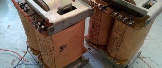
power unit
Checking the audio frequency device should start with the power supply. Most units use simple transformer power supply circuits, and only some designs use pulse voltage converters. If the defect in the audio frequency system is unknown, then before checking, the power supply should be disconnected from the main circuit. This can be done by cutting the printed tracks. Testing the power supply begins with measuring the output DC voltage. If it is very high, you need to check the regulating transistor and zener diodes.
If there is no voltage, check the diode “bridge” and the presence of alternating voltage on the secondary winding of the power transformer. The tester should check the electrolytic capacitors of the filter. A bipolar power supply is checked in a similar way, since the electrical circuits at “+” and at “-” are usually the same. If there are faulty parts, they should be replaced and the presence of DC output voltage checked.
Troubleshooting before car amplifier repair
Before you start work, you need to find out what is broken. Only by determining which part caused the system to stop can it be restored. The electrical circuit will not work if there is no contact, the connection is not in the place where it is intended.
To detect a malfunction caused by a lack of sound, diagnostics begin with a frequency amplifier. To get acquainted with the circuit you will have to remove the cover. Using a magnifying glass, examine the components. If a capacitor or track is burnt out, the wiring does not hold, this is quite clearly visible. It also happens that the problem is not visible here.
Then you need to check if everything is normal with the power supply parts, find out the voltage value that is present at the input. If a blackened resistor is found, a new one is installed in its place.
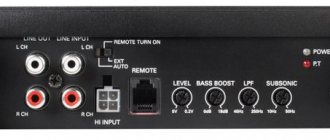
By supplying power to the car amplifier and to the output, which is designated Remou, it is necessary that a short circuit to positive occurs. The light on the indicator will tell you what the problem is. The protection can work:
- if the transistor breaks down;
- due to a malfunction of the voltage converting device;
- in the absence of power.
Input indicators are checked when no such problems are identified. If the device shows the correct number, which is 2x20, you will have to work on the converter transformer. The diode assembly may not function in it. Having discovered a breakdown due to which the protection was triggered, repairing the car amplifier will not seem so difficult.
Watch a video about how to repair a car amplifier yourself.
Amplifier path
The next step is to check the output stage. A common malfunction is the breakdown of power terminal transistors. If the device fails during operation, you need to touch the housings or heatsinks of the output semiconductor devices with your finger. Strong heating of the radiator indicates that the transistor is broken. Using the tester, you can easily check the base-emitter and base-collector junctions. If there is any doubt, it is better to remove the transistors from the board. In order to properly repair an audio amplifier, one tester is not enough. To work you will need a low frequency generator and an oscilloscope.
If the power supply and output transistors are working properly, you need to look for defects in the pre-final and preliminary stages. To do this, a signal from a generator with a frequency of 800 Hz-1 kHz and an amplitude of 100 mV must be sequentially applied to the cascades of the audio frequency unit and the passage of the signal through the speaker system must be controlled. When repairing structures with high output power, you need to use an equivalent load instead of speakers, and monitor the signal with an oscilloscope.
Designs assembled on specialized integrated circuits do not have discrete elements. The board may contain power filter capacitors and input capacitance. In this case, any diagnosis does not make sense. If the supply voltage of the device is normal and there are no breaks in the input and output circuits, then the microcircuit will have to be changed. In automotive systems, defects in printed wiring are common faults. Such violations occur among Chinese manufacturers. Poor-quality soldering is damaged by shaking and vibration, and the automotive low-frequency unit fails.
Car amplifier repair
It's no secret that to get high-quality sound and powerful bass in a car, you definitely need a power amplifier. Today, fortunately, you can find car amplifiers on the market to suit every taste, it all depends on your specific needs. To power standard car speakers, an amplifier of 200-400 watts is enough, but among us there are true connoisseurs of sound pressure, audiophiles and music lovers, who will not be surprised by a couple of hundred watts of sound power.
It is for such people that class D amplifiers were invented - digital audio amplifiers that have high efficiency, compact size and many other advantages.
Unfortunately, a car amplifier sometimes breaks down, in some cases the repair is more expensive than the initial cost of the amplifier itself, so it is very advisable to consider or try to repair it yourself, because sometimes the cause of the breakdown can be a blown fuse. Having at hand a simple and cheap multimeter with a diode testing mode, you can find most of the defects that are very often observed in many car amplifiers.
Any car amplifier consists of three main parts - a voltage converter, a block with power amplifiers and a filter block (crossover).
The voltage converter or inverter is the most vulnerable part in any amplifier - 90% of problems are related to this unit. The converter essentially powers the entire amplifier, including the filter bank.
Exclusively all voltage converters are made according to a standard push-pull circuit using a PWM controller, most often on TL494. Then everything is standard - driver, power transistors, transformer, rectifier and filter block. Some amplifiers (cheap) implement inverter circuits of an unstabilized type - in a word, there is no control of the output voltage, of course this is quite bad, but not a necessary process at all if the amplifier is not sensitive to the supply voltage and is a cheap model.
Converter transistors are the ones that fail most often. In cheap Chinese amplifiers, the transistors are strangely marked, even if you can’t find similar transistors, then you just need to know one thing - the keys can always be replaced with IRFZ40/IRFZ44/IRFZ46/IRFZ48 or with the more powerful IRF3205, the choice of keys is actually quite large, I just listed the most available options. In general, exclusively in all car inverters, high-power N-channel field-effect transistors are used - up to the brutal IRF1404.
Initially, we check the board by eye - sometimes visible defects may be observed (burnt out resistor, broken tracks on the back side of the board, etc.)
Before replacing transistors, you must first check the power fuse, the diode on the plus and minus buses (when the power is reversed, it also burns out), and only after you are convinced that everything is ok with these parts, we replace the keys.
For more professional repairs, you can’t do without an oscilloscope. Initially, you need to check for the presence of rectangular pulses on the 9th and 10th pins of the generator microcircuit; if they are present, then the microcircuit is working. Next, we check for the presence of the same pulses after the driver - on the gates of the field switches. If there are no pulses, then most likely the problem is in the driver; if there are, then without hesitation we replace the field-effect transistors.
It is extremely rare that there is a problem with the power amplifier; the converter burns out first, saving the amplifiers. Other breakdowns are possible in the converter, although they are very rare. There may be a problem with the input and output capacitors or the diode rectifier, which rectifies high-frequency alternating voltage from the transformer.
Author: AKA KASYAN
.
Simple malfunctions of computer speakers and their repair
Almost any malfunction of computer speakers can be repaired by a semi-skilled electrician who knows how to use a tester (multimeter).
Computer speaker repair
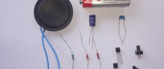
Lack of sound from the speakers can be caused by such simple faults as a broken wire in the amplifier's 3-pin plug, a broken power cord, a blown fuse, a broken wire from the amplifier to the speakers, or a failure of the speakers themselves.
The functionality of the speakers can be checked by picking up the 3-pin input plug; then, with a working sound system, the 50 Hz background will be clearly audible from both speakers. To check the left and right channels of the audio system separately, you need to pick up a thin screwdriver by the metal and take turns touching the contacts of the left and right channels on the three-pin input plug.
Thus, it is possible to determine the performance of each system amplifier separately. The amplifier can be powered directly from the computer via a USB connector or via a 220 V network. The 5 V voltage at the end of the USB cable can be checked with a tester. If the power is supplied via 220 V, then the 220 V voltage on the primary winding of the transformer and the output voltage on the secondary winding are checked.
External view of a computer speaker amplifier. Amplifier chip under the radiator
If there is no voltage on the secondary winding, then the resistance of the primary winding on the transformer is checked, having first disconnected the speakers from the network. If there is no resistance, then the transformer needs to be replaced. The resistance of the primary winding can vary from hundreds of Ohms to kOhms, depending on the power of the transformer.
You can check the speakers for functionality using a tester. In this case, if the speakers are working properly, a slight click should be heard and the tester will show a resistance of 4 or 8 ohms. Without a tester, the speakers are checked using a 1.5 V battery. Its output is applied to the speaker contacts, as a result of which we hear a noticeable click and see the movement of the speaker cone.
Repair services for vintage audio and radio equipment
- Diagnostics
- Prevention
- Repair or restoration of the radio receiving part
- Repair or restoration of the amplifier part
- Repair of tube radio equipment and radio receivers
- Repair of transistor radios
- Repair or restoration of an electric player
- Repair or replacement of potentiometers and switches
- Conversion of the radio receiving part for FM reception
For many connoisseurs of vintage tube equipment (radios, amplifiers, record players) and collectors, the presence of original parts in the equipment is very important and, as a result, the compliance of vintage equipment with the sound characteristics laid down in it by the manufacturer without replacing electrical circuit components with more modern analogues. We stock a significant number of lamps and other domestically produced post-war components.
Repair of vintage audio equipment and equipment - types of services:
- Repair of tube radios using original components
- Repair of transistor radios
- Tube Amplifier Repair
- Repair of transistor amplifiers
- Repair of vinyl and shellac record players in radios
- Restoring the original appearance of tube radio equipment
- Delivery of equipment for repair in a stationary workshop
A short list of brands of equipment serviced:
Telefunken, Nordmende, Neumann, Philips, Siemens, Sony, Graetz, Saba, Blaupunkt, Grundig, Radione, Baltika, Estonia, Latvia, SVD, Zvezda, Mir, Record, Festival, Moskvich, etc.
For all questions related to placing an order for the repair of vintage tube audio equipment and receiving advice on repairs, please contact the service center dispatch service by phone: +7(495) 150 3783
REPAIR OF DOMESTIC SOUND AMPLIFIERS
Recently, two high-class ULFs arrived for repair. I want to share a description of the problems and the results of the repair with visitors to the “Radio Engineering” website. The first amplifier, Brig-001, the left channel did not work. The reason turned out to be the preamplifier.
The capacitor also replaced the transistor. I looked for the fault with a regular player, taking the sound from it and checking it step by step - that’s how I found the faulty element.
The second amplifier, Amphiton-002, was restored using a similar test method. The reason was also in the preamplifier, but in addition to this, the variable resistor on the sound control had to be restored.
I drilled it out, graphite from the cylinder onto the track, graphite pad, pulled out the graphite slider from another alternator, assembled it back using 1 mm wire, since I couldn’t find such bolts.
Some tips for self-repairing ULF. When you turn it on for the first time, immediately monitor the voltage at the power supply output. If it is very low, there may be a short on the board. In this case, we quickly turn off the amplifier and inspect the boards, or by unsoldering various components we find the problematic one. However, sometimes the cause is dried out filter electrolytes. This can be determined by checking the voltage at the output of the power supply at idle.
ULF output stages consume significant current and can burn out if not operated correctly. In this case, it is possible to replace low-resistance current-measuring resistors in the supply circuits of transistors with ratings of 10-20 Ohms. This will prevent burnout of the output transistors and will make it possible to monitor the zero at the output, the absence of RF excitation and the quality of the output signal on an unloaded amplifier, as well as approximately estimate the quiescent current by measuring the voltage drop across them.
The quiescent current after the repair has been carried out must be checked by the voltage drop across the current-measuring resistors of the output stage when the radiator is cold and hot. It should not differ by more than two times; the opposite indicates poor performance of thermal stabilization and may be the cause of further failure.
The photographs show wiring diagrams and printed circuit boards of these amplifiers - for educational purposes. And the schematic diagrams for these and other domestic ULFs are in the BOOKS section. Repaired devices: Fez.
ULF repair forum
- REPAIRING A PHONE THAT WILL NOT CHARGE
- CIRCUIT REPAIR: DISASSEMBLY-INSTALLATION, SELECTION OF ANALOGUES
- REPAIRING BROKEN PLASTIC
- SEARCHING FOR THE CAUSE OF DEVICE MALFUNCTION