A purely triode amplifier with claims to true High-End.
Why triodes? Firstly, the triode is truly a classic - the progenitor of all electric vacuum devices. Compared to pentodes, triodes have lower gain, but also lower internal resistance. The first requires greater amplification of the preliminary stages (which, in principle, is not a very difficult task), and the second has a beneficial effect on improving the damping of the output transformer.
↑ Idea
The idea of creating an amplifier design with a truly classic retro sound has been brewing for a long time. But the idea was fully formed when, while sorting through an old warehouse, I discovered 6N13S triodes.
We decided on the lamps.
The next question, which still does not have a clear answer, is it two-stroke or single-stroke (I can imagine how many comments there will be on this question). I'll express my opinion. For me, the decisive argument, paradoxically, was that these days it is difficult to find highly sensitive acoustics. This means you need power. Working in parallel is a method, not a principle. We also take into account that triodes have worse efficiency compared to pentodes. And finally, the argument in favor of choosing a push-pull cascade on triodes was the fact that in the spectrum of triode harmonics the most significant is the even second harmonic, with a much smaller odd third. Considering that in a push-pull output stage the even harmonics of the output tubes are largely compensated, it is not difficult to draw a conclusion.
ULF power supply
To power the circuit, a TC 20/60 type transformer was used, which was rewound to produce the output respectively: 6.3 V 3 A and 180 V 250 mA.
The lamps are heated using an alternating voltage of 6.3 V. Resistors R8 and R9 balance the voltage, reducing network hum. LED D indicates amplifier operation. A constant anode voltage (+ Uz) is obtained after rectifying the 180 V AC voltage (rectifier bridge M) and filtering it through an RC filter consisting of high-voltage capacitors C1, C2 and C3 and resistor R1. Resistor R2 discharges the capacitors after the power is turned off.
↑ Scheme
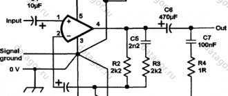
Let's look at some features of the circuit design.
The scheme does not claim to be particularly original; all solutions have been repeatedly described in the literature. But during the assembly process even the principle had to be changed several times. Not everything worked out as planned. The power supply according to the concept is made on kenotrons. The bias selection was automatic, and separate for each lamp (R19-C7, R20-C8). This allows you to not select lamps so carefully and monitor the current during the aging process. Output stage lamp mode Ua=270V Ia=70 mA (class A mode). Typically, the pre-output stage is a phase inverter, but due to the fact that the output stage has a low gain, increased voltage is required on the control grids. In this regard, in this case, the pre-output stage (V2A, V2B) is also designed according to the circuit of a symmetrical push-pull amplifier with a common cathode resistor R14. The advantage of such a cascade also lies in the fact that due to the antiphase of the alternating components of the cathode currents V2A and V2B, there is no alternating (sound) voltage on resistor R14 and therefore there is no need to bypass it with an electrolytic capacitor.
Another original solution, which I really liked, was spied on by Uim de Jager
(“Elektor Electronics” No. 6/2007, pp. 38-44)
. Hybrid "auto-fixed" offset. Supplying voltage from a negative source - 50V through resistor R11 and from the common wire through R14 increases the effective supply voltage of this stage and allows it to develop up to 70V AC audio voltage (rms value) at the anodes without limitation.
The input stage at V1A, V1B is made according to a differential amplifier circuit. The complete symmetry of all cascades along the anode circuits has one more positive quality - good compensation for ripples and interference of the anode supply voltages. Switch S1 allows you to close or open the circuit of the general feedback with a depth of 10 dB, which makes it possible to select the most acceptable sound for the acoustics and ears.
About amplifier tubes
Popular imported ECC83 triodes with low power consumption were used as a pre-tube. They have high gain (about 100), high internal resistance and low anode current. To power the filaments, you can use two voltages - 6.3 V or 12.6 V. To supply 12.6 V, the filament voltage must be supplied to pins 4 and 5 (connected in series). If there is an available voltage of 6.3 V, we connect the filaments in parallel by shorting pins 4 and 5 and also applying voltage to pin 9. The lamp current consumes 150 mA at a voltage of 12.6 V or 300 mA at a voltage of 6.3 V.
A low-voltage Soviet-made 6H13C double triode was used as the end lamp. This lamp contains two triodes with a power of about 13 W each in a beautiful glass container. It can be powered from a low voltage of 90 V and the anode current is 70-90 mA (each triode). There's not much gain, only about 2.5.
The filament voltage is 6.3 V, while the required glow current is quite large, up to 2.5 A. The lamp is very hot during operation, remember this when designing the amplifier.
↑ Project revival
And so let's get started.
Despite the simplicity of the circuit design, implementation was fraught with problems like never before.
Relatively high currents and significant power dissipation on the elements constantly required adjustments to the design. Initially, it was planned to make a power supply on one 5Ts3S kenotron. But due to the huge voltage drop and the maximum operating mode of the lamp, such a powerful kenotron had to be abandoned. I had to use two (in parallel) 5Ts4S. But as they say, everything is not done for the better. 5Ts4S allows the supply of anode voltage without preheating, which made it possible to abandon the delay circuit or an additional anode voltage switch. The calculated power of the 6W cathode resistors also did not withstand the thermal regime. I had to use vitrified 25W.
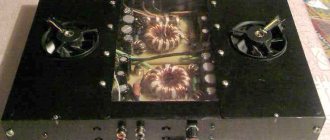
But the most mysterious thing was the operation of the TS-180 power transformer. At optimal currents and loads, its heating was extreme. In anticipation of advice and assumptions, I will say that almost all options have been tried, from replacing the magnetic circuit to rewinding. Current consumption under load is 0.8A according to the label 0.85A maximum heating - mysticism! We change the design and install a fan. Everything is fine, even original.
But what are we talking about sad things? The main circuit works and produces the stated parameters practically without adjustment. Elementary compliance with installation rules, no background interference.
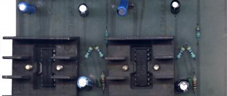
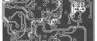
For the first time I used hybrid installation - the main elements are located on a printed strip, and the connections to the panels are mounted with overhead conductors. To be honest, classic wall-mounted installation is simpler and less problematic. Well, as usual, there is a delay with the design and manufacture of the case.
TRIODED TUBE AMPLIFIER “FOCUS”
Somehow it always turned out that I built my tube amplifiers with output stages based on beam tetrodes and pentodes. For some reason, the output triodes did not fit into my designs. Perhaps the common opinion that triode sound is good only for classical, vocal and jazz played a role (I mostly listen to rock), or perhaps because I have a larger selection of tetrodes and pentodes. In general, be that as it may, I decided to fill this gap and try a triode. For the famous and quite expensive 300V, 2A3, 2S4S, etc. There was no point in trying without experience, so I opted for indirectly heated powerful stabilizer triodes 6N13S (6N5S is their complete analogue). They are not suitable for a single-cycle amplifier due to their “inherent curvature,” but they are suitable for a push-pull amplifier. The Uim de Jaeger scheme, which is a classic “Williamson”, was chosen as the initial one. You can get acquainted with all its advantages and disadvantages here; here I will only give the original diagram.
I immediately disagreed with Huim de Jaeger on the issue of biasing the output tubes. With the selected quiescent current of 70 mA for each triode, the four automatic bias resistors turn into a hellish oven, so it was decided to convert the bias of the output stage lamps into a fixed one. In addition, this approach also improves the sound of the amplifier. There were no other disagreements with the author of the scheme, so otherwise it remained unchanged. A 6N2P was initially planned as the input tube, a 6N1P for the second stage, and, as I already said, a 6N13S was staked out for a place in the output stage. I redrew the diagram in my own way and present it to your attention.
Well, now is the time to think about nutrition. In my slightly modified amplifier circuit, I had to separate the anode power supply of the first two stages and the output one, since the 6N13S is a relatively low-voltage lamp. Therefore, in the power supply I will need two anode rectifiers - 180 V for the output stage and 270 V for the first two. You will also need two “underground” sources: -50 V for the drive stages and -100 V for biasing the output stage lamps. In order to extend the life of the lamps, which is far from infinite, it would not hurt to build a simple soft start with a delay and a smooth supply of anode voltage. Based on these considerations, a seemingly scary power supply circuit appeared.
After the first shock and a closer look, we see that there is nothing terrible. Three capacitors in the circuit of the primary winding of power transformer T1 form a simple network noise filter, resistor R1 is a discharge one. Winding 4-5 of the transformer is anode to power the output triodes. Fast diodes are used in rectifiers to reduce switching noise. The rectified voltage is smoothed by capacitive and electronic filters, and the electronic filter has a separate active element (transistor) for each channel, which is done to decouple stereo channels by power supply. A similar circuit is used to assemble the +270 V anode voltage source for the first two stages. Electronic filters are switched on by electromagnetic relay K1 approximately 45 s after the amplifier is connected to the network. That is, first the lamp filaments warm up without anode voltage, and then this voltage gradually increases over about 1 minute.
Resistors R10 and R17 discharge the filter capacitors after the amplifier is turned off. Two “underground” rectifiers connected in series are powered from windings 8-9 and 10-11 of the power transformer. They provide two negative voltages: -50V for the drive stages and -100V for biasing the output stage tubes. The “silovik” has two filament windings - one for each channel. Resistors R2...R5 form a midpoint to which a positive potential is applied from the divider R6R7. This is done to eliminate the 50Hz hum that would inevitably occur.
All fixed resistors in the amplifier itself are MLT with the power indicated on the diagram. It would be better to choose carbon ULM or BC, but, as they say, we have what we have. Current measuring R19 and R20 with a tolerance of 1%. It is advisable to install a high-quality volume control R1, a lot depends on it. I still have the Chinese TOMY, the flight is normal. Electrolytic capacitors will be hot, so I had to fork out for 105-degree ones. The requirements for interstage capacitors have long been known to everyone; I used MKR X2, which at a low price showed their best performance. C1, C8 and C9 – film. For now, the output transformers will be incandescent TN33, if I can find human ones, I will replace them. The power supply has the same picture - MLT resistors and 105-degree electrolytes. Moreover, the filter containers are bridged with film, and the containers at the outputs of electronic filters are bridged with paper in oil. The hastily assembled layout of one channel inspired some hopes for the success of my enterprise.
My body, as always, starts from anywhere. This time I came across a piece of duralumin of suitable size, but two rectangular holes were cut in it, which I had to struggle with a lot, since they were completely out of place. I turned this piece this way and that for a very long time, until I finally managed to “compose the design” in a more or less acceptable way. After marking, drilling and cutting the necessary holes, I thoroughly went over the sheet with coarse sandpaper and kerosene, and this is what came out.
The next step is to attach the lamp panels and the milliammeter, which was previously disassembled and two yellow LEDs were glued into it to illuminate the scale.
I mounted the amplifier circuit using a hinged method, on the petals of the lamp sockets and a common busbar, which is mounted above these sockets. Trimmer resistors for adjusting the bias are located on the far side of this panel-chassis and allow, if necessary, to quickly adjust the quiescent current of the output triodes.
Now it's time to make the body itself. And I decided to make it from beech cutting boards, cutting them into pieces of the required size. The back wall is made of textolite 6 mm thick and covered with beech-like self-adhesive. It contains input connectors and a socket for the network cable, combined with a fuse compartment. In the front panel I drilled mounting holes for self-tapping screws, as well as holes for the volume control and toggle switches - network and switchable OOS. The wooden parts were sealed with glossy clear varnish from a spray can.
When they were dry, I attached paper-oil capacitors to the sides using tin staples. I installed a volume control, also providing it with a yellow LED and decorating it with two discs made of gray and black plastic. I collected everything in a heap and saw that I had missed the height of the sides. I had to screw a wooden ruler to them from below to increase their height. Result:
Finally, both parts of the body are screwed together with self-tapping screws. Further assembly will now be in a full-fledged case.
A box with four holes behind the capacitor and there is a block with trimming resistors to adjust the bias. The resistor shafts are slightly recessed into the surface of the block so that accidental contact does not disrupt the adjustment. Next, I install the output terminals, output transformers and connect them according to the diagram. I connect a network toggle switch, a milliammeter with a switch. Well, and so on.
Now the power supply . I assembled it on a printed circuit board and secured it in the basement under one of the output transformers, and the power torus under the other. I cut the wires to the required length so that there are no loops, and tie them together with zip ties.
First start! There are no sparks or smoke, the lamps are warming up, the anode voltage is increasing... Christmas tree needles! Instead of 270 V anode I see 340, and instead of 180 V - 210! An unfortunate mistake! I measure the modes of the lamps - in the first two stages the power dissipation on the anodes does not exceed the maximum permissible limits, in the output stages it is exceeded by 1 W. Well, increasing the supply voltage makes the driver more linear, which is even better. And I will reduce the currents of the output lamps a little, although this is not necessary. Now you can move on to measuring the amplifier parameters. I wonder what kind of animal it turned out to be.
I must say in fairness that the first tests were not very encouraging. For some time I played with lamps of the first and second stages and finally settled on this “configuration”. In the first cascade there was a pair of successfully purchased 6N2P-V with “VP” stamps. But in the second cascade, the obviously used Novosibirsk 6N1P-E from the 60s, found in the bins, unexpectedly appeared. Interestingly, their electrode system is completely different from that of conventional 6N1P, it looks more like 6N3P. So: these lamps sound just great! I give you a picture: on the left is 6N1P-E, on the right is the usual 6N1P.
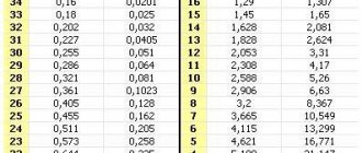
I return now to the topic of measurements. I carried them out in two modes - with the OOS open and with the OOS closed at the same output power - 10 W. In the first case, the sensitivity was 0.2 V, in the second 0.45 V. The test results are in the plate:
Recorded frequency response for modes with open and closed feedback loops, respectively:
Yes, this, of course, is not a fountain, but let’s take a moment to remember what kind of output transformers are in the amplifier. That's right, TN33. Can we expect miracles from them? Of course not. But even with all this, I am very pleased with the sound of my first triode (precisely triode, not pseudo-triode, where tetrodes and pentodes are connected according to a triode circuit) amplifier. You feel power, freedom, relaxedness in sound, excellent bass, clear highs. Precision and focus, hence the name of the amplifier - Focus. There is no hint of lethargy and dryness, as seasoned representatives of the “pentode chamber” characterize the triode sound. When the OOS is closed, the sound becomes somewhat clamped, as if compressed. I prefer the non-OOS sound, despite its worse parameters. This is exactly the case when the scales tip in favor of subjective perception rather than measurement results.
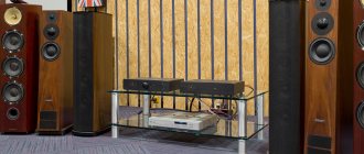
All that remains is to close the amplifier from the bottom with a lid with holes for ventilation, screw on the legs, put the output transformers in stainless steel circles and seal the mounting holes on the front panel with decorative overlays, which was done. Now it's finally ready!
This is the final form of the tube amplifier, which I decided to call "Focus". The author of the project is Gamzan.
ULF Forum
- SIMPLE TRIODE PREAMPLIFIER
- TUBE ULF ON 6F3P (6BM8, 6PL12, ECL82)
- TUBE FOR HOME AUDIO SYSTEM
- TUBE ULF FOR 6P14P AND 6N2P
↑ Final chords
The logical conclusion of the design is a subjective assessment of sound quality.
The device was immediately delivered to the specialists. The “luminaries,” as one would expect at the beginning, ruined both the design and the construction (well, that’s why they are “luminaries”). Either I regretted the hardware or the fan should be installed for no less than $10, well, of course, I’m already calm about this. Well, finally the amplifier started playing. From the abstract praises about the triode sound, I realized that the amplifier was a success. The sound without OOS is especially impressive, and the sound dynamics are amazing. With OOS the sound is smoother, but it gives the impression of some compression (by tube standards). I’ll say it again, the quality of the phonogram is of great importance. Listening to original CDs with a deep dynamic range - jazz, rock - gives special pleasure. It’s hard to describe how banal the sound of the Beatles’ “Abbey Road” inspired so many nostalgic feelings. Unfortunately, it was not possible to listen to it on a rare acoustic system (it went to a new owner) of an open type (analogous to the “Symphony 2” acoustic system) without any bass reflexes and bags of cotton wool on the 6GD2 speakers. According to experts, such a duet would give an unforgettable sound.
In conclusion, the verdict: SPRING is an amp worth repeating.
Recipe and ingredients
Body made of laminated chipboard 16mm thick. Internal fastening: slats, screws, glue. I did not further thicken the walls (except for the lower part of the front panel), citing the fact that the acoustics are low-power.
Internal damping of the body: felt, padding polyester.
You need to put a sealant under the speakers or “plant” them on plasticine.
Base: chipboard with decorative aluminum corner around the perimeter.
test
Adjustable legs, based on crab furniture nuts.
Filter – capacitor MBGShch-2 4uF 160V.
Speaker connection is in-phase.
Internal copper wires 1.5 mm "Odeskabel".
Soviet instrument banana connectors (turned bronze contact in a carbolite housing).
Amplifier-AC cable: Odescable 2X4mm; Profigold banana connectors.
Total: $72.
After assembling the case, securing and connecting the speakers, place the speakers in the desired position in the room. Listen to your favorite music at a volume that interests you. Add felt and padding polyester “to taste”, achieving the desired shade and sound.
Thank you for your attention and I wish you success.