Power supply for audio amplifier
Power supplies intended for use in audio power amplifiers (AMPs) are subject to special requirements. And the higher the class of the sound amplifier, the higher these requirements. The most important of them is a minimum of pulsations and various types of electromagnetic radiation. For this reason, even low-end audio equipment uses exclusively transformer power supplies. Switching power supplies (UPS) have no place in audio equipment.
During operation, UPSs generate a wide range of electromagnetic radiation, which has a detrimental effect on sound quality. This is explained by the operation of semiconductor devices in key mode. As a result, current pulses occur. Which ultimately spread in the form of electromagnetic radiation and pulsations. For this reason, UPSs are subject to mandatory shielding.
To smooth out rectified current ripples, high-capacity electrolytic capacitors are used in transformer (linear) power supplies. Moreover, it is recommended to use special capacitors for power supply amplifiers. However, their impact on improving sound quality is still controversial. But the cost of such capacitors clearly exceeds the cost of “ordinary” capacitors.
The key element of most audio amplifiers is the op-amp. Op amps are often powered by bipolar voltage, although they can also receive power from a unipolar source. But still, powerful amplifiers are powered, as a rule, from bipolar current sources.
DIY stereo sound amplifier
And so, to make a sound amplifier it is enough to understand the following. Any UMZCH has at least one input, one output and two pins for connecting power.
Since we will be assembling a stereo audio amplifier on the TEA2025B chip, two inputs will be used. Each input is on a separate channel. And accordingly, two outputs will be used to connect two speakers: left and right.
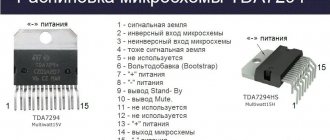
Now we can draw the following conclusion. Any stereo audio amplifier chip must have at least six pins. Two inputs, two outputs, two power supplies. As a rule, microcircuits of this type have more pins. Additional elements are soldered to them: capacitors, resistors, which are popularly called “piping” or “loose”.
Sound amplifier on TEA2025B
TEA2025B is powered over a wide range of unipolar voltage: 3…15 V. Output power in stereo mode is 2 x 2.3 W. The load is two speakers, the voice coil resistance is 4 ohms. You can also send a mono signal to the microcircuit. Then one speaker will serve as the load.
Important!!! Train yourself to check the circuits found on the Internet with the typical connection circuits given in the datasheet of the corresponding microcircuit. Errors are very common. Therefore, it would not be a bad idea to look at the original source. Because chip manufacturers do not make mistakes in technical documentation, unlike amateur radio sites.
We will make a stereo amplifier.
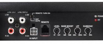
First of all, to connect to the output of the sound card of a computer or smartphone, or simply to the audio output of another device, such as a receiver or tuner, we need an audio plug.
Audio plugs are available for mono signal (single-pin), stereo signal (2-pin), stereo with microphone (4-pin). In our case, it is necessary to use a 2-pin audio plug and without a microphone.
One pin is the left channel. The second pin is the right channel. The third contact is the common wire for the two channels.
To avoid mistakes, it is easiest to ring the place where the wires are soldered with the corresponding pins.
And so, the plug is ready, but for now we are not soldering it anywhere.
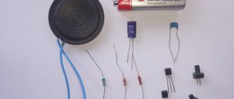
We will also need two very simple, but identical in characteristics, speakers. Speakers with a power of 3 W and a voice coil resistance of 4 Ohms are quite suitable.
Note that the speakers also have a polarity that represents the start and end of the voice coil. In the future, we also need to adhere to it.
The next required component of any audio amplifier is the power supply. A 9 V or 12 V power supply with a power of 9 W or more is suitable. To find out how to make such a power supply, follow the link.
I'll be using the variable output voltage power supply that I showed how to make in my Beginner Electronics Technicians course.
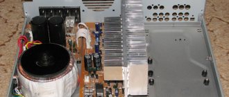
Finding the radiator size
Two amplifier channels are connected to the heatsink:
The chip must be attached to a heatsink, otherwise it will quickly overheat and be damaged. The size of the heatsink will depend on the maximum power dissipation and thermal resistances along the heat flow path from the TDA2050 chip.
Maximum power dissipation
Maximum power dissipation (P dmax) is the amount of power that the TDA2050 will dissipate as heat at its operating limit. P dmax depends on the maximum supply voltage from the transformer and the speaker resistance:
According to the data, the absolute maximum parameter of the TDA2050 for P dmax is 25 W. If your amplifier's P dmax exceeds 25 W, you must reduce the supply voltage or increase the speaker impedance to prevent damage to the m/s.
For the amplifier we are making here, the maximum supply voltage from the transformer is ± 24.7 V, and 6 Ohm speakers are used, so P dmax:
P dmax 20.6 W is below the TDA2050's absolute maximum of 25 W, so it's fine.
Heat sink thermal resistance
Now we can determine the maximum thermal resistance (in °C/W) of the heatsink required to dissipate all the power generated by the TDA2050. But first you need to find out the values of three thermal resistances along the path of heat flow from the microcircuit:
- 0 jc: Thermal resistance from the chip junction to the outside of the plastic case.
- 0 cs : thermal resistance from case to heatsink.
- 0 sa: thermal resistance from the heatsink to the surrounding air.
Heat dissipation will be more efficient when any of them becomes smaller. There is nothing we can do to get a lower 0 jc value because it depends on the chip design. 0 cs can be reduced by using thermal paste between the chip and the heatsink. Thermal paste's thermal resistance is typically around 0.2°C/W.
The greatest reduction in thermal resistance will occur when choosing a radiator (0 sa). The thermal resistance of a heat sink is usually listed in a table as °C/W. Heatsinks with lower thermal resistance will dissipate more heat, meaning they are better.
Use this formula to calculate the maximum heat sink thermal resistance required to dissipate P dmax TDA2050:
- 0 cs TDA2050 is 3°C/W.
- T jmax – maximum junction temperature, or the temperature at which the thermal protection circuit is turned on. T jmax for TDA2050 is 150 °C.
- T amb – ambient temperature during operation of the amplifier. Typical value is room temperature (25°C).
The maximum thermal resistance of the heatsink for this amplifier with P dmax 20.6 W is:
Therefore, you will need a heatsink with a value of no more than 2.9 ° C / W to ensure that all the power produced by the amplifier is dissipated.
Assembling a sound amplifier for TEA2025B
Now that all the additional elements are assembled, we can focus on the TEA2025B chip.
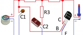
Taking a closer look at the diagram, we will discover one positive point. Six electrolytic capacitors have the same rating - 100 µF. This is great, because often in many microcircuits the “piping” consists of radio components of different ratings, which creates some inconvenience.
Please note that although the microcircuit is designed for a maximum of 12 V, electrolytic capacitors should be used with a voltage of at least 25 V.
To adjust the volume level of both channels simultaneously, a dual variable resistor with a logarithmic dependence is used. Then the constant resistors shown in the photo above are not needed.
I didn’t bother with the PCB layout and made it quickly in the Sprint Layout program. If you are not too lazy to make a better wiring from scratch, then you can share it with other novice electronics engineers. You can send it to my email, and I will attach it to this article. I think everyone will thank you.
Now all that remains is to do the most enjoyable part - solder all the radio components into the printed circuit board and connect the plug and speaker terminals.
I hope now you can make any amplifier with your own hands.
Download TEA2025B_ board layout
Tools
The main set of tools is the list present in every man’s home.
- Pliers.
- Crosshead screwdriver.
- Slotted screwdriver.
- Soldering station with stand.
- Tester, also called multimeter.
In addition to the above tools, you may also need a hand drill and a drill set. Similar materials will be required if the board for the sound amplifier is also made independently by hand.
You should also prepare a cutter, with the help of which tracks and other areas for the passage of current are marked on the board. You can assemble a class “A” amplifier with your own hands without any specific tools.
Note!
Do-it-yourself charger for a car battery: a step-by-step guide for making the device at home, selecting materials for assembling the structureDIY laboratory power supply | Step-by-step instructions on how and from what elements to build a power supply
DIY antenna for digital TV - photo instructions on how to make simple antennas for digital TV