With the development of stereo technology, one of the problems of analog equipment has sharply worsened - the low quality and short service life of variable resistors that serve as volume controls. And if for mono equipment it is still possible to select a variable resistor to replace a failed one, then for stereo, especially imported, this is almost impossible.
Finding a “about the same” resistor is very difficult even in large cities. Moreover, most often the volume control resistors “break”. The tone and balance controls are used less often and last much longer. Fortunately, complete failure of a dual (“stereo”) variable resistor is extremely rare. Usually at least one of the resistors is fully or partially operational. And, “hooking” on this part of the regulator. You can “cure” the entire device!
In this case, you don’t even have to switch the system to monophonic mode—you just need to add a special electronic volume control chip. Such microcircuits are relatively cheap, almost do not distort the sound and practically do not require connecting external elements. With their help, the author at one time brought back life to more than a dozen different radio tape recorders, and not a single owner was left disappointed.
As a rule, such microcircuits are voltage controlled. By changing the voltage at a special input of the microcircuit using a variable resistor (or what is left of it), we change the volume phase in both channels, and the linearity and synchronism of its change is much higher than when using a dual variable resistor.
It is not at all necessary to know exactly how such microcircuits are designed (in fact, it is an operational amplifier with an electrically variable gain), you just need to remember that when the voltage at the control input decreases, the volume usually also decreases. And even if the variable resistor is “not subject to restoration,” all is not lost either. In this case, you can use a digital volume control, which is controlled by buttons.
There are two types of such regulators: stand-alone and requiring the use of an additional processor. The first ones (for example, KA2250, TS9153) regulate only the volume. The “quality of adjustment” is pretty bad, but their cost is relatively low. “Processor” controls are twice as expensive as stand-alone ones, but much “cooler”: the control is more linear, and, in addition to adjusting the volume, you can adjust timbre, balance, sound effects (pseudo-stereo - stereo from a mono signal, like the TDA8425 or pseudo-quadra-stereo in microcircuits of the TEAbZxx series).
There is also a channel selector at the input and some other gadgets. But the proliferation of such regulators, even despite the very favorable price-quality ratio, limits the need to use an external, pre-programmed processor. The author has not seen specialized programmed processors for working with such microcircuits on sale.
Most electronic volume control chips are designed to work in a cassette recorder. They have a pair of sensitive and low-noise preamplifiers, a pair of power amplifiers with electronic volume control, and are designed for low-voltage power supply (1.8 ... 6.0 V with a current consumption of about 10 mA).
↑ The essence of the idea
I came up with the following (I didn’t find any analogues on the Internet, and if there is, it’s a coincidence): the analog signal is supplied to the coupling capacitor C1 and the operational amplifier U1 (Figure 2), connected via an inverting circuit with a gain of 0.3, set by resistors as R3/R2. The need to attenuate the signal was clarified after assembling the first experimental sample. The reason will be described below. Next, the signal is fed to the keys of a microcontroller-controlled attenuator of the “R2R” type. Then (Figure 3) to a non-inverting amplifier (second half of U1) with a gain of approximately 4 (1+ R29/R28) and further to its intended purpose, for example, a final amplifier or, as in my case, a crossover for bi-amping.
Figure 2. Input buffer
Figure 3. Output Buffer
↑ Further ideas
The idea was developed by Peter Baxandall, who is famous for his tone control and other developments. He has a design for an "improved volume control" using op-amps and a potentiometer in the feedback loop. The adjustment dependence practically coincides with the design on passive elements described above, and is also close to logarithmic, but the circuit on active elements can provide both amplification and attenuation of the signal. An example of such a design can be found in Project 24, and the basic idea is shown in Fig. 3.
An input buffer (U1A) is required to provide high input impedance.
The maximum gain of the stage at U1A is 10 (20 dB), and the minimum gain is 0 (maximum attenuation). The input impedance is variable, depending on the potentiometer setting. At minimum gain, the input impedance is equal to the 50 kΩ potentiometer impedance. Input impedance drops to approximately 27k ohms when the potentiometer is turned to 50%, and to approximately 4.3k ohms at maximum. The input impedance is much lower than that of a potentiometer due to the feedback from the final op amp. These resistance figures are similar (but slightly lower) than the passive version (if a 100kΩ potentiometer is used), and a low output impedance of the signal source is required, otherwise the logarithmic relationship will not hold.
The actual value of VR1 doesn't matter, potentiometers from 10k to 100k will work equally well, although the input impedance will be affected. The dependence of the adjustment on the angle of rotation is shown in Fig. 4.
Please note that due to the absence of an additional resistor according to the circuit in Fig. 1, the difference in the spread of resistors of different channels is not leveled out here, therefore, for their better balance with each other, attention must be paid to the identity of the resistances. 20 dB of gain will be excessive for most preamps. Typically, a gain of 10 dB is sufficient. To obtain such amplification, it is enough to increase R2 to 3.3 kOhm.
↑ More about the attenuator
At one time I made a signal generator on ATmega8, where an “R2R” matrix was used as a DAC. I decided to use something similar on the regulator. I will describe in detail the most significant digit of the regulator; the rest differ only in the serial numbers of the elements. The input signal through resistor R4 is supplied to the element R2R of the matrix (since the regulator is 6-bit - resistors 6R2 and 6R1, respectively). This bit is controlled by transistor Q1, which, when opened, shunts the signal to ground. Resistor R5 locks the base in the absence of a control signal. To avoid interference from the digital part, I decided to open the transistor through optocoupler U3. Power is supplied to the optocoupler transistor through current-limiting resistor R6, and the diode current is limited by resistor R7. I didn’t really select the ratings, I just looked to ensure that the current matches the data from the datasheets. The optocoupler unlocks the transistor when a logical one appears at the corresponding output of the shift register U7. A small note: for the least significant bit, resistors 1R1 and 1R2 must have the same value of 2R.
Figure 4. Attenuator Schematic and Parts List
↑ About management
The ATMega8 microcontroller is used to control the operation of the regulator, but you can use any other microcontroller that meets the following requirements: three free lines of the input/output port (clock for register clocking, data for data transfer and storage for data fixation). Below is the function that sends data to the shift register. I do not claim authorship, because... This code can be found on the AVR devices website. There is nothing complicated about it - a cycle based on the number of transmitted bits, in which a mask is applied to select one bit and the corresponding output to the port, and at the end we pull the strobe to fix the data in the register. The function of sending data to the register under the spoiler.
Show/Hide text
#define SH_CP PORTC.0 // data strobe #define DS PORTC.1 // data #define ST_CP PORTC.2 // data storage strobe // output to shift register void putout (unsigned char temp) { unsigned char copy_temp; unsigned char counter; copy_temp = temp; for (counter = 0; counter < 8; counter++) { // loop for 8 bits // Check the leftmost bit, if it is 1 then write to data line 1 if (copy_temp & 0Х80) {DS = 1;} else {DS = 0;} // otherwise we write 0 // Drag our foot to push the bit into the register SH_CP = 1; SH_CP = 0; copy_temp = copy_temp < < 1 ; // Shift all the bits of the temp variable to the left by one bit } // Drag our foot to save the data in the register. ST_CP = 1; ST_CP = 0; DS = 0; };
It is worth saying that this attenuator operates in inverse mode with respect to data bits: when the value “0” is output to the register, the volume will be maximum, “63” will be minimum. The attenuator, if necessary, can be easily scaled by a certain number of bits with an increase in the number of control stages.
On the printed circuit board, the low-order bit is connected to pin Q1 of the register (and not Q0, as would be more logical), this is due to slight difficulties in routing the tracks, since Q0 is located on the other side of the microcircuit than pins Q1-Q7. With this in mind, you should shift the output code to the left by one bit (“<< 1” in C or “shl 1” in Asm). In my program you can notice a shift not to the left, but to the right. This is due to this: for control I have a mechanical encoder and the algorithm for calculating it changes the counter variable by 4 in one click, that is, initially the volume variable is calculated with a shift to the left by 2 discharge.
↑ Impressions
To begin with, I was just interested in building a digital volume control myself.
I didn't really hope for success and was pleasantly surprised by the result. I soldered the first version, connected the generator and an oscilloscope and saw how the signal amplitude began to gradually decrease with the rotation of the encoder. Hooray! I decided to connect it to an amplifier. And then it turned out that with an amplitude greater than 1300 mV, the lower half-wave begins to be cut off. This is due to the breakdown of the transistor by reverse voltage, which I didn’t think about at first. The second version introduced an input buffer with a gain of 0.3. I figured that this would be enough for a linear level signal, because the breakdown voltage for the bc547 transistors used is 650 mV and -650/0.3 = approx. 2 Volts, which is quite enough to work with a linear output (the final permissible input amplitude is limited by the supply voltage of the operational amplifier +15 Volt and -2 Volt breakdown of the transistor).
I didn't notice any difference by ear compared to a conventional variable resistor. It would be nice to measure the coefficient of nonlinear distortion, but, unfortunately, there is nothing with which to measure it. I think this design can be used not only as a level regulator for an audio signal, but also for any signal with the corresponding replacement of key transistors. Power supply for the digital part is +5 Volts. The power supply for the analog part is bipolar ±15 Volts, it is advisable to organize it from a stabilized, filtered power source.
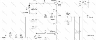
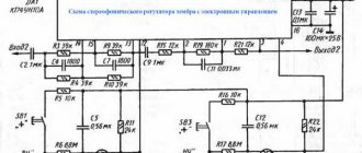
Chip TDA1524A.
The regulator unit is developed based on the TDA1524A microcircuit. The choice fell on it simply because it turned out to be one of the microcircuits that required minimal wiring, and it was possible to purchase it on the local market at a reasonable, although, in my opinion, slightly inflated price, which amounted to $2.
The TDA1524 microcircuit can be powered from a voltage of 7.5 to 16.5 V, with a current consumption of 15... 56 mA.
The adjustment range for high frequencies is: –15… +15dB (±3dB), and for low frequencies: –19… +17dB (±3dB).
↑ Oscillograms of the regulator operation
I apologize for the quality of the photo, and there is no better oscilloscope either.
Figure 5. Input signal
Figure 6. Output at maximum level
Figure 7. Alarm at half volume
Figure 8. And the signal at “zero” (the measurement limit was reduced by 10 times)
↑ Mono version
The following trick is used in some guitar amps. Dual potentiometers are used, which is not very suitable for stereo, since quad linear potentiometers are quite scarce. The diagram is shown in Fig. 5.
The approximation to the logarithmic relationship is very good, at least in the 30 dB range, somewhat better than the version shown in Fig. 1. The dependence of the adjustment on the rotation angle is shown in Fig. 6.
When the level decreases from the maximum in the range of 25 dB, the dependence is almost linear (i.e. truly logarithmic). This is a good way to get good results, but as noted, a stereo amplifier requires a quad potentiometer. This limits the usefulness of this solution.
↑ About manufacturing and details
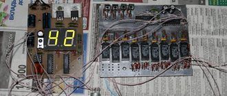
The board turned out to be one-sided 70x45 mm (Figure 9). It is worth noting that the board has one regulator channel, so if you need stereo, you need to make two boards. All microcircuits are in DIP packages. The resistors of the optocoupler collectors are 0.25 Watt (less is possible), the rest are 0805 SMD. It would be nice to use a better operational amplifier, in my version AD822 (I tried the TL072 and did not hear a noticeable difference).
Figure 9. Printed circuit board
Figure 10. Pair of assembled channels
↑ Translator's Notes
I do not guarantee the absolute accuracy of the translation.
I have not done any practical experiments confirming the author’s measurements. At the same time, the material is interesting and technical solutions that are found in different designs and articles are collected here. Logarithmic potentiometers of the required size and rating are very difficult to find, which was one of the reasons for this translation. However, most modern signal sources and homemade preamplifiers have a very low output impedance, which allows the use of the described improved volume control.
Thank you for your attention!
↑ Files
Full diagram and seal: