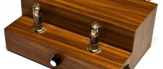
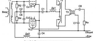
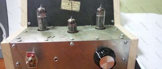
Hello to all radio specialists, fans of tube UMZCHs. Recently I also built a light bulb, the diagram and design of which I hasten to share with you. This is a very interesting circuit, the settings are minimal, the connection between the stages is not through a capacitor, but direct, there is no background at all. This diagram is a variation on a theme from the Radio 5-2012 .
First, read the original article: This amplifier has a power of about 3 W with a speaker impedance of 4 ohms. Operating frequency range - 30 Hz - 20 kHz.
Hi-End tube amplifier units
Lately, tube audio amplifiers seem to be experiencing a rebirth. They are collected not only by radio amateurs, but also mass-produced by well-known manufacturing companies from many countries. In some countries, the production of radio tubes, which were discontinued back in the 1970-1980s, has even been resumed.
And all this happens despite the seemingly obvious disadvantages of lamps compared to semiconductor devices:
- the presence of incandescence that consumes significant power;
- high anode supply voltage (300 V or more);
- short service life (500-1000 hours).
| Main types of vacuum tubes These types of vacuum tubes are the most common. Diode - it has two electrodes: a cathode and an anode. This lamp is used in detectors, as well as in industrial frequency AC rectifiers. Triode - contains an additional electrode - a grid. By changing the voltage on the grid, you can control the anode current of such a device. Triodes are widely used in amplifiers and electrical oscillators. Tetrode - unlike a triode, it also has a second screen grid. The screen grid is grounded at high frequency, which makes it possible to reduce the throughput capacitance of the lamp (i.e., the control grid-anode capacitance) and make the lamp more high-frequency. In this case, over a wide voltage range, the anode current is practically independent of the voltage at the anode. The disadvantage of the tetrode is the so-called dynatron effect - at close voltages on the anode and the screen grid, secondary electrons knocked out of the anode do not return to the anode, but enter the screen grid, which leads to a failure in the anode characteristics of the lamp. A beam tetrode is a 4-electrode tube that, to reduce the dynatron effect, uses a special design of the tube electrodes to focus the electrons flying toward the anode into narrow beams. As a result, secondary electrons knocked out of the anode do not reach the screen grid. A pentode is a 5-electrode lamp with an additional protective grid located between the anode and the screen grid. The screen grid is typically at zero potential, which prevents secondary electrons from reaching the screen grid. Audiophiles often say: “The shorter the “path” of the audio signal in the UMZCH, the better it sounds.” The reason for the fascination with tube audio amplifiers is also that a good tube amplifier contains much fewer parts (the “sound path” is shorter) than a similar transistor amplifier (in which the sound signal passes through dozens of transistors), while providing better sound quality. This is despite the fact that tube UMZCHs almost always have a higher nonlinear distortion coefficient (THD) than transistor ones. This is due to the fact that a number of companies have become too carried away with the production of UMZCHs, in which the output stage is made on an IC, which has led to a noticeable deterioration in the sound of even amplifiers advertised as belonging to the Hi-Fi class. Let us also note this fact, it has long been known that a transistor UMZCH (even not on an IC, but on discrete transistors), having a bandwidth of 20 Hz-40 kHz and THD = 0.01%, sounds, ceteris paribus, worse than a tube one , having a bandwidth twice as narrow and a THD of more than 1%. This is due to two reasons:
|
1. Circuit design of lamp UMZCH
It differs significantly from the circuit design of UMZCH on semiconductor devices, due to a different principle of operation of the lamp as an amplifying device than that of the transistor. If in a semiconductor device a stream of charged particles flows in a solid crystal, then in a lamp the electrons emitted by the cathode move in a vacuum. Therefore, all amplification lamps are classified as electric vacuum devices.
Another significant difference between lamps and semiconductor devices is the almost complete absence of variation in characteristics. Lamps with the same name, for example 6N1P, from different batches and produced by different factories have the same characteristics.
An important circumstance affecting lamp circuitry is the fact that the cathode of the lamp is heated to a temperature of 700...900°C, so changing the ambient temperature from -30 to +50°C has virtually no effect on the operating mode of the lamp. Therefore, there is no need to take circuitry measures to stabilize the temperature of the lamp operating mode, as is done in transistor amplifiers.
Among music lovers and designers of tube UMZCHs, there is an opinion that triode or pentode and tetrode type tubes used in triode connection are most suitable for amplifying the sound signal. The fact is that the anode characteristics of the triode and pentode differ significantly, and the UMZCH on a triode introduces much less distortion into the input signal than the UMZCH on a pentode. In order to better understand the operating features of a particular lamp UMZCH or to develop such an UMZCH yourself, it is necessary to take into account the characteristics of the operation of lamps in various circuits for their inclusion, i.e. know the advantages and disadvantages of each of these schemes. Let's look at some types of triode amplifier stages used in UMZCH.
Common cathode cascade
Most often in tube UMZCHs, both in the preliminary and single-ended output stages, a circuit with a common cathode (OK) is used. The load is connected to the anode circuit ( Fig. 1 ). The following can be used as R in such a cascade:
- in the output stages - a transformer;
- in drivers - throttle;
- in the preliminary stages of the UMZCH there is a resistor. It is important to note that the lowest distortion and best sound quality of such a cascade (minimum SOI) is ensured by using a transformer as a load, and the worst performance is achieved when using a resistive load. Obviously, the cost of such an amplifier when using a transformer or inductor in it will be higher than when using a resistive load. However, for such amplification stages with a transformer or inductor, it is necessary to correctly position the amplifier elements on the chassis. The signal at the output of the cascade with OK will be opposite in phase to the input signal, i.e. This is an inverting amplifier.
Advantages of the cascade:
- simple calculation methods and ready-made circuit solutions for lamps of various types;
- minimum elements;
- simple implementation of the bias circuit;
- low cost.
In the cascade, instead of automatic bias through elements RK and CK, a fixed bias can be used if a zener diode is switched on instead of Ra. In this case, due to the high noise level of the zener diode, it is necessary to use high-quality C.
Disadvantages of the cascade:
- high input capacitance;
- the gain provided by the OK cascade is always below the lamp's nameplate gain;
- the cascade requires the use of high-quality C with significant capacitance (470-1000 µF).
Capacitor C can be removed from the cascade. In this case, the output resistance of the cascade will increase, i.e. it will be more difficult to coordinate both with the load and with the subsequent cascade. At the same time, removing SK will lead to a decrease in the SOI of the cascade, since in this case local current feedback is formed in the cascade. At the same time, the gain of such a cascade will decrease.
Cascade with common anode
This cascade ( Fig. 2 ) is also called a cathode follower. This stage does not invert the phase of the input signal. When using a high transconductance lamp in a cascade, you can obtain the minimum output impedance of the cascade. This can be important when working with high-power output lamps that operate in the first grid current mode. The cascade can also operate on a load with significant input capacitance. To reduce the THD, it is desirable that the load resistance of such a cascade be greater than 5-1RK.
Advantages of the cascade:
- low output impedance (theoretically it is equal to 1/S);
- high input impedance;
- wide bandwidth;
- small input capacitance.
Disadvantages of the cascade:
- in some circuits, with a large voltage drop across the resistor R, the voltage between the cathode and the heater may be high, in this case the filament should be powered from an individual filament winding for this lamp;
- the OA cascade does not amplify the voltage of the input signal - it only amplifies its power;
- the cascade is covered by 100% local environmental feedback, and this, according to a number of developers, introduces distortion into the audio signal.
Cascade with a common grid
It is also called a cascade with a grounded grid (Fig. 3). The cascade is characterized by a low input impedance and is the highest frequency of those previously considered. The fact is that the intra-lamp capacitance “control grid-anode” in such a cascade is connected in parallel to the load, which means it does not form frequency-dependent feedback between the control grid and the anode.
The circuit shown in Fig. 3 is often used in the output stage of an UMZCH that operates as a control grid drain. In this case, the THD of the output stage will be less than when using a circuit in which the driver input signal is applied to the control grid (i.e., when using a common anode or common cathode circuit). A cascade with a common grid is non-inverting. Advantages of the cascade:
- greater linearity when using such a connection in the output stages of UMZCHs operating with grid currents.
Disadvantages of the cascade:
- low input impedance.
Anode follower
Such a cascade ( Fig. 4 ), like a cascade with a common anode, has a low output impedance, a low SOI level and a wide operating frequency band. Compared to the cascade with OK, the anode follower is covered by feedback (OS) through resistor R2. By changing the ratio of the values of resistors R1 and R2, you can adjust the gain of the cascade, including making it equal to 1.
The advantages of the cascade are the same as those of the cascade with OK.
Flaws:
- low input impedance.
Phase inverted cascade
To operate push-pull UMZCHs, signals that are opposite in phase must be supplied to their input. For this, you can use, for example, either a transformer or a phase-inverted cascade with a divided load ( Fig. 5 ). Advantages:
- the circuit contains a minimum of elements;
- good balancing of output signals, depending mainly only on the accuracy of selecting the same values of resistors Ra and Rk.
Flaws:
- The voltage gain of such a stage is approximately equal to 1;
- the cascade has a low overload capacity, so the level of the signal entering it should be low;
- The output resistances of the cascade at the “-” and “+” outputs are different.
Differential amplifier
It is also called a balanced cascade ( Fig. 6 ). Used in driver circuits of the push-pull output stage of the UMZCH. The signal can come to it, for example, from a phase-inverted cascade ( Fig. 5 ).
Advantages:
- the same output resistance at the “-” and “+” outputs;
- low level of own noise;
- low requirements for filtering the supply voltage.
Flaws:
- Two power supplies with positive and negative voltage are required.
Cascode amplifier
This amplifier uses two triodes connected in series ( Fig. 7 ). Hence its name - triode cascade. This stage provides much more amplitude gain to the input signal than a single triode stage. Theoretically, the gain of such a cascade is equal to the product of the gains of the triodes included in it.
Advantages:
- low noise level, which is determined by the noise level of triode VL1;
- high voltage gain;
- good linearity at large output signal amplitudes;
- wide bandwidth;
Cascade with dynamic load
It is also called a µ-repeater ( Fig. 8 ). The name of the cascade is due to the fact that its gain is almost equal to the nameplate gain µ of the lamp, i.e. significantly higher than that of a cascade with a common cathode. Advantages:
- low SOI;
- low output impedance (approximately 0.25Ri of VL1 lamp);
- high gain;
- low sensitivity to supply voltage ripples.
Flaws:
- high voltage between the lamp cathode \/1_2 and the heater.
Cascade with cathode coupling
This cascade ( Fig. 9 ) is essentially a cascade connected in series with a common anode and a common grid. In this case, there is a galvanic connection between the cascades.
Advantages:
- high linearity of amplitude characteristics;
- wide bandwidth;
- small input capacitance;
- high input resistance.
Flaws:
- two different polarity power sources are required;
- It may be difficult to implement lamp biasing.
Cascode cathode follower
In foreign literature on audio engineering, such a cascade ( Fig. 10 ) is also called a “White cathode follower.” Such a cascade resembles a hybrid of a common-cathode cascade and a cascode amplifier. A feature of the cascade in Fig. 10 is the presence of feedback through the capacitor Coc, which limits the lower operating frequency of the cascade. Thanks to the use of two tubes, the stage provides a very low output impedance. The voltage gain of such a stage is practically unity, and it does not change the phase of the input signal.
Advantages:
- low SOI;
- very low output impedance;
- low sensitivity to supply voltage ripples.
Flaws:
- high voltage between the cathode and the lamp heater \/L2;
- presence of OOS.
New trends in circuit design of lamp UMZCHs
In the 1950-60s, UMZCHs were built almost exclusively on vacuum tubes (powerful high-frequency transistors were not yet produced at that time). If you look at the typical UMZCH diagrams of those years, what is striking is the desire of the developers not only to ensure serial suitability of the UMZCH, without using a careful selection of elements, but also their desire to save both due to the cost and due to the dimensions of the UMZCH. Therefore, in those years, more economical, but providing worse sound quality, push-pull UMZCHs were used. In the output push-pull stages, the operation class of AB, AB2 and even B lamps was used. To reduce the number of lamps in the UMZCH, tetrodes and pentodes were widely used, which have a higher SOI, but provide a higher gain of each stage. As a result, such amplifiers sounded little better than modern UMZCHs made entirely on ICs, but, by the standards of those times, they were quite cheap.
Currently, trends in the development of tube UMZCHs have radically changed - the output stage of the UMZCH (like all others) operates in pure class A. Most often, single-ended output stages with a transformer output are used. All UMZCH stages use only triodes (or pentodes and tetrodes in a triode connection), which provides a significant improvement in sound quality. At the same time, for UMZCH developers, the determining factor is the sound quality, and not the efficiency and not the final cost of the UMZCH.
Typical 1950s-60s audio preamplifier
Fans of the High-End concept believe that the construction of an UMZCH must be uncompromising - it cannot be hybrid (i.e., contain both lamps and transistors), but must contain only lamps. Thus, the signal from a CD/DVD player or a high-quality computer sound card must pass through a minimum of amplification stages, and all of them must be tube-based only. No hybrid solutions.
Many audio preamplifier circuits were developed in the 1950s and 60s. A typical triode preamplifier circuit, widely used in tape recorders and radios that were popular at that time, is shown in Fig. 11 .
This is a diagram of the UMZCH radio "Rigonda" developed by Riga. It was designed to receive broadcast stations in the long, medium, short and ultra-short wave bands. Sound reproduction could be stereophonic or monophonic, depending on the configuration of the radio. This amplifier, in addition to amplifying the input signal, also implemented bass and treble tone control, which made it possible to improve the sound quality of a sound recording or radio broadcast. Currently, tone control in UMZCH, especially in the High-End class, is not used due to the availability of high-quality signal sources.
The main characteristics of this UMZCH, given in the radio data sheet:
- Reproducible frequency range 60... 15000 Hz.
- The rated electrical output power of the UMZCH is 2 W, the maximum undistorted power is 3.5 W.
- Adjustment of bass and treble tone - within 14...18 dB.
- The background level from the UMZCH input is 56...60 dB.
The radio's acoustic system consists of four loudspeakers: two 4GD-28 (with resonant frequencies of 60 and 90 Hz) and two 1GD-28 (with resonant frequencies of 100 and 140 Hz), the last two are connected to the TP 1 transformer through a C10 capacitor.
The low-frequency amplifier ( Fig. 11 ) uses two stages based on a 6N1P double triode. Volume adjustment is carried out by the loud-compensated regulator R1. To adjust the bass tone, a frequency-dependent voltage divider and variable resistor R3 are used. A special feature of this UMZCH is the use of a differential circuit with positive and negative feedback to adjust the HF tone. This is achieved by connecting a variable resistor R4, according to an alternating signal, between the cathode and anode of triode L1.2.
The output stage is made using a 6P14P type L2 lamp (a specially designed “sound” pentode) according to an ultralinear circuit. However, to reduce the SOI of the UMZCH, general negative feedback is used from the secondary winding of transformer Tr1 through resistor R14 to the cathode of lamp L2. In this case, the purpose of capacitor C12 (its nominal value is 2200 pF) is to prevent excitation of the UMZCH at high frequencies.
If we talk about feedback, then in this amplifier there is also local negative feedback on alternating current, namely in the first amplifier stage, the value of capacitor C5 was chosen to be 0.033 μF instead of 10...20 μF, in order to provide greater RF amplification by the RF cascade on L1.1 .
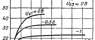
To analyze the operation of such an amplifier, we will use the current-voltage characteristics (VC) of the 6N1P lamp used in it ( Fig. 12 ).
The rated anode current of the 6N1P lamp is 8 mA. In this case, it is only 2.5 mA, i.e. more than 3 times less. At a bias voltage of -2 V and an anode voltage of +80 V, the lamp will operate at the initial, extremely nonlinear section of its current-voltage characteristic. And although the L1 lamp operates in class A, this will lead to a significant increase in the SOI of such a cascade. To see this, you need to mark in Fig. 12 the operating point of the lamp at a mixing voltage of -2 V and an anode voltage of +80 V.
All this is caused by the incorrect choice of the value of the anode load resistor R4 - it is too high. There are recommendations for the operation of a triode in the linear section of the characteristic: “this stage with a common cathode should have a rating of R4 equal to 5 ... 10•R.” For a 6N1P type lamp, Ri is equal to 11 kOhm, i.e. the optimal rating of R4 is from 55 to 110 kOhm, i.e. it is more than two times smaller than in the circuit shown in Fig. 11 . Yes, and in the passport data for the lamp the mode is indicated: la = 8 mA, Ua = 250 V.
To ensure a minimum SOI, the operating point of the triode must be located in the middle of the linear section of its current-voltage characteristic. As can be seen from Fig. 12 , at a bias voltage of -2 V, this condition corresponds to a point with an anode voltage of 160 V and an anode current of 8 mA, i.e. The voltage at anode L1 must be increased almost 2 times.
However, in order to ensure this, the cascade supply voltage will have to be significantly increased. So, with an anode current of 8 mA, we select the minimum value of the R4 rating equal to 51 kOhm. In this case, the voltage drop across R4 will be 408 V, i.e. The cascade supply voltage (voltage at the anode L1 + voltage drop at P4) should be: 160+408=568 V.
The situation is similar with the stage on L 2. And this despite the fact that the supply voltage of the output stage of the UMZCH is only 270 V.
In this regard, the question arises: “Should the design of the UMZCH be complicated in order to ensure the minimum SOI of the first two stages of the UMZCH, when the SOI of transformer Tr1 is very large?” This is exactly what the developers of tube equipment thought in the 1950s and 60s. At the same time, they did not forget that a power supply with an output voltage of 568 V would be very bulky and expensive, primarily due to the high-voltage electrolytic capacitors used in it.
Improving input stage parameters
Let's look at how you can improve the parameters of the input stage on a 6N1P lamp without significantly increasing the power supply voltage. To do this, you can, for example, use a cascade with a dynamic load, discussed earlier ( Fig. 8 ).
The UMZCH circuit with a supply voltage of 360 V (which is significantly less than the optimal 568 V for the amplifier shown in Fig. 11) and an input stage with a dynamic load, which uses a 6N1P lamp, is shown in Fig. 13 . The advantages and disadvantages of such a cascade were discussed earlier.
Note that it is advisable to replace filter resistor R6 with a choke. In this case, the voltage at the anode VL2.1 will be about 355 V. To ensure optimal operation of both triodes \/L1.1 and VL1.2, it is desirable that this voltage be divided equally between them, i.e. the anode voltage of each triode will be 177.5 V at a given Ucm = -3 V, the anode current will be 9 mA ( Fig. 12 ). This mode is close to optimal for this type of lamp. To reduce the THD of the cascade, you can try to select the value of resistor R4 in the range of 0.5...2•RЗ.
Another version of the pre-amplifier, with a high gain (about 35), is shown in Fig. 14 . It divides the load in the anode circuit \/L1.1, i.e. The AC load for \/L1.1 is not only the triode \/L1.2, but also resistor R5.
In this case, the voltage drop across resistor P6 is used as a bias voltage for \/L1.2, and the control grid VL1.2 is connected via alternating current to the anode VL1.1 through capacitor C1. Moreover, each lamp operates with an anode voltage of 100 V, which is not optimal for this type of lamp. As can be seen from the current-voltage characteristics shown in Fig. 11 , in this case, at Ua = 100 V, Ucm = -3 V, the anode current \/L1.1 will be 2.8 mA, i.e. the operating point of the cascade is in the nonlinear section of the current-voltage characteristic, and such a cascade will have a fairly significant SOI. The way out of this situation is to increase the voltage on the anode VL1.2 to at least 350 V in order to increase both the anode-cathode voltage and the anode current of each of the triodes.
Calculation of the output stage of the UMZCH
In this case, we will give an example of calculating a classic single-ended output stage on a pentode, shown in Fig. 11 (it is assembled on L2).
Note that there are tables of typical modes for lamps when used in a single-ended output stage with an output power of 0.1 ... 5.5 W. A special feature of this cascade is the presence of a transformer, which allows the UMZCH to be matched to a load with almost any resistance.
If the UMZCH uses a typical operating mode for a given lamp, then its parameters, such as UC0, I0, µ, S, Ri, Ra, can be found in the passport data for the lamps. If you are using a non-standard operating mode of the lamp, you must use the lamp’s current-voltage characteristic for calculation.
Calculation sequence:
- A constant voltage is set on the shielding grid. As a rule, UE = UA0.
- According to the anode characteristics of the lamp (Fig.15) are given:
- maximum anode current IAMAX - it is determined for the UC=0 mode. As a rule, this current corresponds to a voltage UA=(0.1…0.25)UA0;
- minimum tocanode IA MIN=0.1·IAMAX. In this case, the voltage on the control grid corresponding to IAMIN will be the maximum negative value of this voltage - UC MAX.
- The constant negative voltage on the grid will be: UC0 = UC MAX/2, i.e. the operating point on the current-voltage characteristic is selected at the intersection of the curve for UC = UC0 and the vertical line for UA0 (point “0” in Fig. 15 ). Since it is assumed that this cascade operates in a mode without grid currents (otherwise its SOI will increase sharply), the amplitude of the input signal should not exceed UC0. Thus, we obtain the working section of the dynamic characteristic between points A and B in Fig. 15 . The lamp anode current will be maximum at point A and minimum at point B.
- It is checked that at the selected operating point the maximum power dissipated at the anode does not exceed the permissible:
RA ADD = UA0·IA0,
Where:
RA DOP - maximum permissible power dissipation at the anode of a lamp of this type;
UA0 - anode voltage at the operating point [V];
IA0 is the anode current at the operating point [A].
Author: Andrey Semenov, Kiev
Source: Radioamator No. 1, 2 2015
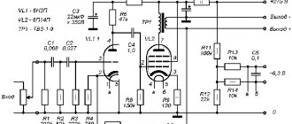
Claim
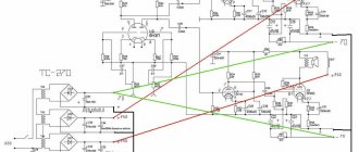
1. A tube amplifier with direct inter-stage coupling and separate power supply of the stages, characterized in that the anode of the first lamp is connected to the grid of the second lamp, and a resistor is connected between the point of their connection and the cathode of the second lamp, while the cathode of the second lamp is connected to the positive pole of the power source of the first cascade and to the negative pole of the power supply of the second stage.
2. Tube amplifier according to claim 1, characterized in that a resistor is connected between the grid of the second lamp and the positive pole of the power source of the second stage.
3. Tube amplifier according to claim 1, characterized in that it has two identical arms for amplification in push-pull mode.
4. Tube amplifier according to claim 2, characterized in that it has two identical arms for amplification in push-pull mode.