I offer a diagram of a device that is easy to manufacture and set up. This is a power regulator, not much different in functionality from other similar devices, a wide variety of diagrams of which can be found on the Internet.
Personally, I was inspired to make this regulator by several circumstances:
1) the need for smooth regulation of the luminous flux of a half-kilowatt group of halogen lamps; 2) temperature adjustment of the heating element section; 3) dimming of LED groups when operating from different voltages; 4) ballast for a music center, purchased by friends on EBAY, designed to operate on a 110-volt AC network.
↑ Disadvantages of thyristor and triac circuits
I decided to abandon the thyristor regulator circuits that I had previously made several times for many reasons that did not suit me: a) difficult to eliminate interference;
b) high control current; c) complete opening of thyristors (triacs) without taking special measures to complicate the circuit; d) a significant voltage drop, increasing the power dissipated by the device; e) the impossibility of normal operation of a powerful triac at low currents. In fact, the problem indicated in paragraph “a” can be solved by solid shielding and filtering of the power circuits, synchronizing the triac control circuit with the zero value of the network sinusoid, but these measures will inevitably lead to a deterioration in the weight and size parameters of the device and to its increase in cost.
It is also impossible to use a triac circuit as a ballast due to the complete opening of the triac at the time of switching (without complicating the circuit), which can lead to failure of the device powered through such a ballast.
And, of course, a universal regulator must operate normally over a wide range of load currents.
↑ General recommendations
Due to high voltages and the influence of leaks, flushing the board is absolutely necessary. There should be a small gap between the parts and the board. After setting up the board, it is advisable to cover it on the foil side with a layer of “Plastik” varnish or similar.
Divider R1R2 allows you to smoothly regulate the voltage on the load and, if necessary, extinguish excess voltage. I turned off about 50 V in the headphone amplifier. This is easier than changing the power transformer. Smooth voltage supply is beneficial for lamps and smoothes out transients.
It should be noted that short circuits in the load are unacceptable - the filter transistor will instantly fail. During preliminary setup, if there is no confidence in the installation of the amplifier and the serviceability of the elements, the filter can even be replaced with a constant resistor, for example, MLT-2. For this amplifier with a current consumption of 0.1 A and a voltage drop across the filter of 20 V, an MLT-2 200 Ohm resistor is suitable.
I find making universal filter boards “for future use” simple and useful. The boards do not need to be configured. You only need to mold the capacitors, especially if they are new, and check the input and output voltage, and if necessary, adjust the latter.
It is advisable to view the voltages at the input and output of the filter. To avoid failure of the oscilloscope, voltage must be applied to its closed input.
At the same time, it turned out that the separating capacitor at the input of C1-94 has a leak, so to observe at the limit of “10 mV” it was necessary to turn it on through an additional high-quality (of course, not “electrolyte”) capacitance with a polypropylene dielectric.
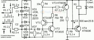
↑ Power regulator circuit using field-effect transistors
Fragment excluded. The full version is available to patrons and full members of the community.
However, be that as it may, I decided to assemble
a regulator using field-effect transistors
(hereinafter referred to as FET) with PHI control. Unlike PT circuits with phase-pulse control, where the circuit is tied to the frequency of the mains voltage, with PWI control the control circuit generates its own sequence of pulses, modulating the mains frequency. By changing the width of these pulses, a change in the value of the output voltage is achieved.
The regulator circuit turns out to be quite simple, low-noise and operational at any current values in the load. I'll start with the performance characteristics. Up to 200 W, field-effect transistors practically do not heat up
(for this purpose, their complete opening by pulses of the control circuit is ensured). When operating the regulator with a load with a power greater than 200 W, radiators should be installed on the PT. So, for example, with a load power of 1 kW, on an open PT channel having, say, a resistance of 0.1 Ohm, the voltage drop will be about 0.45 V, and the dissipated power will exceed 2 W, which will inevitably cause heating of the transistor crystal. When operating for a long time at a powerful load (500 W and above), it may be necessary to blow the radiator. When working with a powerful transformer (from UPS - in step-down mode), the secondary winding of the transformer was loaded with a 12-volt automotive halogen lamp with a power of 190 W.
↑ Modular design
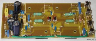
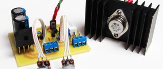
In my opinion, it is convenient to make standard modules, for example, like this.
Radiators measuring approximately 45x45x5 mm from ancient computer boards were used as a heat sink. It is atypical to install parts on the foil side and use pieces of tinned wire from the leads of parts for connection points. This is done to simplify installation - the board is held on the terminals of the field-effect transistor (and fits tightly to it) quite firmly, the transistor with the board is attached with one screw to the heat sink. At first I provided a second point for attaching the board to the radiator, then abandoned it. The photo shows the installation quite clearly. For safety reasons, insulating sleeves and gaskets are used.
I highly recommend it, otherwise there will be a voltage of 300 Volts on the heat sink body.
The 03N60S5 transistor used in the TO-220 package can dissipate up to 2 Watts at room ambient temperature. The total current of a single-ended stereo amplifier on 6N3P and 6P14P is approximately 0.1 A, with a voltage drop across the filter of about 20 V, the thermal power will be just 2 Watts, so even a small heat sink can easily cope with its task.
If you use a filter on each channel, each transistor will dissipate only 1 Watt. But this is in a steady, static mode, but when the power is turned on, the voltage drop across the filter will be significant, as will the thermal power. Therefore, heat removal is necessary, especially until the transient processes end.
The first version of the board was for small-sized heat sinks; it can be used if there is not enough space (the capacitor in the first photo has been removed for clarity).
↑ Test results
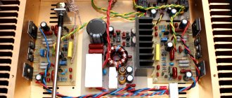
The regulator was assembled on a homemade breadboard by my friend and was tested in operation with various loads: 1) halogen spotlight (200 W);
2) fan heater; 3) LED group from the TV matrix (150 V); 3) electric drill (360 W); 4) various transformers (from power adapters for old modems to transformers from old television receivers). The results were as expected. This means that the “regulator-transformer” combination can be used as an autotransformer and obtain an alternating voltage at the output that is adjustable from 0 to the maximum value.
The result was also a very smooth adjustment of the light flux, both halogen lamps and the LED group.
Adjusting the speed/power of the engines (fan heater and electric drill) was also a success, despite the fact that this function was not of particular importance to me and was investigated for the sake of interest.
Adjusting the power of the 2-kilowatt section of heating elements was successful. The regulator operates stably in a wide range of currents (from tenths of milliamps) and has no voltage surges during switching.
Fragment excluded. The full version is available to patrons and full members of the community.
↑ With the armed eye
Now let's look at the voltage oscillograms at the input and output of the filter.
The peak-to-peak swing is 6 V. At the filter input there is a rectifier bridge and a 120 µF capacitance, at the output there are two 120 µF capacitors, the current consumed by the amplifier is 0.1 A.
The output ripple swing is approximately 6 mV (corresponding to a sinusoidal signal of approximately 2 mV), the ripple shape is smoother, the ripple suppression is about 1000 times!
(the scale in the photo is, of course, different). To suppress possible interference at radio frequencies, you can install an additional LC filter. For me there was no need for this - there was no background or interference to the ear. In higher-end amplifiers, an additional LC filter (with a small compact inductance) is desirable.
What you need to know when charging a battery
When charging a car battery, it is important to follow a number of rules. This will help you extend your battery life and maintain your health:
- All lead batteries are charged with a current no higher than one tenth of the battery capacity. If you have a battery with a capacity of 60 A/h in your car, then the calculation of the charging current looks like this: 60/10 = 6 A.
- Explosive gases may be released during charging. This is especially true for serviceable batteries. One spark is enough for hydrogen accumulated in a garage or other room to explode. Therefore, you need to charge batteries in a well-ventilated area or on a balcony.
- Charging the battery is accompanied by the release of heat, so constantly monitor the temperature of the battery case by touch. If the battery becomes noticeably hot, immediately reduce the charging current or stop charging altogether.
- If the battery is serviceable, constantly monitor the electrolyte level in the banks and its density. During the charging process, the electrolyte “boils away” and the density increases. If the plates in the jar are exposed or the density rises above 1.29, and charging is not yet complete, add distilled water to the electrolyte.
- Do not overcharge the battery. The maximum voltage on it with the charger connected is 14.7 V.
- Do not allow the battery to be deeply discharged; recharge it periodically. If the voltage on the battery drops below 10.7 when the load is off, the battery will have to be thrown away.
The question of creating a simple battery charger with your own hands has been clarified. Everything is quite simple, all you have to do is stock up on the necessary tools and you can safely get to work.
Hello everyone, friends, in this post I want to tell you about a current stabilizer for a charger that almost everyone can assemble with their own hands.
LM317
The use of LM317 (roll) does not even require any skills or knowledge of electronics. The number of external elements in the circuits is minimal, so this is an affordable option for anyone. Its price is very low, its capabilities and applications have been tested and verified many times. Only it requires good cooling, this is its main drawback. The only thing you should be wary of is low-quality Chinese LM317 microcircuits, which have worse parameters.
Due to the absence of excess noise at the output, linear stabilization microcircuits were used to power high-quality Hi-Fi and Hi-End DACs. For DACs, cleanliness of power plays a huge role, so some use batteries for this.
Stabilization circuit up to 10 amperes
The maximum power for the LM317 is 1.5 Amps. To increase the number of amperes, you can add a field-effect transistor or a regular one to the circuit. At the output it will be possible to get up to 10A, set by low-resistance resistance. In this diagram, the main load is taken by the KT825 transistor.
Another way is to install an analogue with higher technical characteristics on a larger cooling system.
Multifunctional device
Drivers for 220 V LEDs are of average complexity. Setting them up can take a lot of time, requiring setup experience. Such a driver can be extracted from LED lamps, spotlights and lamps with a faulty LED circuit. Most of them can also be modified by recognizing the converter controller model. The parameters are usually set by one or more resistors.
Until recently, the universal module XL4015 was very popular. According to its characteristics, it is suitable for connecting high power LEDs (up to 100 Watt). The standard version of its case is soldered to a board that acts as a radiator. To improve the cooling of the XL4015, the circuit must be modified to install a heatsink on the device box.
Many users simply place it on top, however, the efficiency of such an installation is quite low. It is advisable to place the cooling system at the bottom of the board, opposite the soldering joint of the microcircuit. For optimal quality, it can be unsoldered and installed on a full-fledged radiator using thermal paste. The wires will need to be extended. Additional cooling can also be installed for diodes, which will significantly increase the efficiency of the entire circuit.
Among the drivers, adjustable is considered the most universal. A variable resistor must be installed, which sets the number of amperes. These characteristics are usually specified in the following documents:
- In the accompanying documentation for the microcircuit.
- In datasheet.
- In the standard connection diagram.
Without additional cooling of the microcircuit, such devices can withstand 1-3 A (in accordance with the model of the pulse-width modulation controller). The main disadvantage of these drivers is excessive heating of the diode and inductor. Above 3 A, cooling of the powerful diode and controller will be required. The choke is replaced with a more suitable one or rewound with a thick wire.
Stabilized regulated power supply with overload protection
Many amateur radio power supplies (PS) are made on KR142EN12, KR142EN22A, KR142EN24, etc. microcircuits. The lower limit of adjustment of these microcircuits is 1.2...1.3 V, but sometimes a voltage of 0.5...1 V is necessary. The author offers several technical power supply solutions based on these microcircuits.
The integrated circuit (IC) KR142EN12A (Fig. 1) is an adjustable voltage stabilizer of the compensation type in the KT-28-2 package, which allows you to power devices with a current of up to 1.5 A in the voltage range 1.2...37 V. This integrated stabilizer has thermally stable current protection and output short circuit protection.
Fig.1. IC KR142EN12A
Based on the KR142EN12A IC, you can build an adjustable power supply, the circuit of which (without a transformer and diode bridge) is shown in Fig. 2. The rectified input voltage is supplied from the diode bridge to capacitor C1. Transistor VT2 and chip DA1 should be located on the radiator. Heat sink flange DA1 is electrically connected to pin 2, so if DA1 and transistor VD2 are located on the same radiator, then they need to be isolated from each other. In the author's version, DA1 is installed on a separate small radiator, which is not galvanically connected to the radiator and transistor VT2.
Fig.2. Adjustable power supply on IC KR142EN12A