Previously, when computers were bulky, prototypes of the first transistors had not yet left the walls of Bell Labs research laboratories, and no one had heard of the MP3 format, audiophiles were in their analog paradise, enjoying the warm tube music from radios and vinyl players. In this article I will show you how to assemble a tube-based FM radio.
Like any other type of data, sound is now usually stored digitally. Of course, the output sound quality is very dependent on the characteristics of the specific device - the DAC (digital-to-analog converter) and op-amp (operational amplifier) used. But in general, there is no escape from discreteness and quantization of the signal.
Here, of course, you can remember about cassettes, vinyl and turntables. They have their connoisseurs, and even today it is not difficult to get copies of such equipment in good condition. But it will no longer be possible to assemble something similar “on your knees”: it requires rather complex mechanics. What to do in such a situation?
There is an exit! The signal can be taken from the radio air. Moreover, before this was completely trivial: you open a book for radio amateurs and assemble yourself a 1V1 or 1V2 DV/SV receiver - the circuits there are very simple. And within a few hours you can listen to your favorite radio “Maniac”.
Direct amplification receivers are classified by the number of amplification stages before and after the detector. So 1V1 means that the receiver contains one UHF (high frequency amplifier) stage, a detector and one ULF (low frequency amplifier) stage. See the Wikipedia pages for more details.
But that was before, and since 2014, broadcasting in the DV and SV bands in Russia has been completely stopped (the airwaves are noisy and unprofitable). However, in fairness, it can be noted that there has never been high-quality sound on long and medium waves. This is explained by the narrow broadcast bandwidth (about 10 kHz), and its width is directly related to the bandwidth of the transmitted audio signal. Thus, only the FM band will satisfy our needs.
Here things are somewhat more complicated, since direct amplification receivers are no longer effective. Although, of course, they are also sometimes collected, but this is rather exotic. More or less acceptable results can be achieved only by assembling a super-regenerator. The super regenerative receiver has perhaps the best balance of design simplicity and efficiency. You can assemble a working circuit from literally a dozen parts. However, the sound quality leaves much to be desired, and there is practically nothing to be done about it.
WE RECOMMEND: Radio signal interception and analysis
In other words, in order to achieve good results, we are forced to opt for a superheterodyne. A modern FM receiver can be implemented on a single RDA5807 chip, which contains a complete superheterodyne circuit with digital control. It supports stereo and RDS, but more on that another time.
The easiest to implement is a superheterodyne with a low intermediate frequency and a pulse-frequency detector. Such a receiver can contain only one tunable circuit, which greatly simplifies the design. Let's look at the principle of its operation in more detail.
Superheterodyne
A superheterodyne receiver, unlike a direct amplification receiver, involves converting the received signal into an intermediate frequency at which selection is performed. This solution allows you to reduce the number of rearranged elements, which greatly simplifies the task.
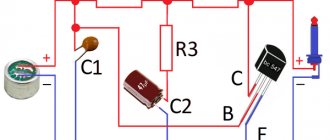
Block diagram of a typical heterodyne receiver
The diagram clearly shows that the received signal is amplified and enters the mixer, and the output from the local oscillator (auxiliary oscillator) is also supplied there. As a result, the mixer signal contains beats, the frequency of which is equal to the difference between the received signal and the local oscillator signal. From the mixer, the flow enters a bandpass filter, which selects an intermediate frequency signal.
It is at this point that selection is performed. Next, the intermediate frequency is amplified and sent to a detector that extracts the audio signal. The latter is converted by ULF and fed to a speaker or headphones. The scheme as a whole is quite complex, but it benefits from the point of view of operational stability.
Is it possible to simplify anything in this scheme? Yes, you can! If you make the intermediate frequency low enough (~200 kHz), then the bandpass filter can be replaced with a low-pass filter, which significantly simplifies the design (in fact, this is how the K174XA34 microcircuit works). Is it possible to simplify the diagram further? Certainly! You can combine a mixer with a local oscillator; such receivers are also called autodynes.
You can read more about the operating principle of a superheterodyne receiver on Wikipedia.
Pulse frequency detector
Now let's take a closer look at the detector. From its name it follows that frequency modulation implies a change in the frequency of the carrier signal under the influence of a modulating signal. This can be demonstrated by the following graph.
The essence of frequency modulation
For the reverse procedure, that is, to isolate the audio signal, an FM detector is used. There are many types of frequency detectors, but the so-called counting detector stands out among them.
The operating principle of the counting detector is quite simple to understand. The frequency-modulated signal is passed through a limiter, resulting in a variable-frequency square wave at the output. After this, a pulse of constant width is generated from the ascending or descending signal. Thus, from a variable frequency signal we obtained pulses with a varying repetition period, and since the pulse width is constant, the duty cycle also changes. That is, we received a PWM signal. The resulting PWM signal is integrated to produce an audio signal at the output.
In general, a pulse frequency detector works exactly the same as a DAC using a PWM generator. However, such a detector has some limitations, and this is primarily the frequency of the input signal, which must be below 1 MHz (assuming that the frequency deviation is 50 kHz, typical for wideband FM modulation), since at higher frequencies the efficiency begins to decrease detector. However, in our case, on the contrary, this is an advantage.
There is a wonderful video that explains the operation of a counting detector with oscillograms.
It is interesting to note that this detector is rarely mentioned in domestic amateur radio literature, and tube designs cannot be found on the RuNet, whereas in Europe and Australia these circuits are quite popular. For example, one of the most famous receivers with a pulse frequency detector was the Sinclair Micro FM. Yes, this is the same Sinclair who developed the ZX Spectrum.
Schematic diagram
So, let's start assembling such a device. Let's take this design as a starting point.
Tube radio receiver circuit
Let's start with the lamps. Obviously, slightly different lamps are available in Australia, where the original circuit was developed, so we adapt the set of parts to what I have in stock. So, at the input there is 6BL8, and this is a complete analogue of our 6F1P, which has always been used for URCHs and converters.
The anode circuits of radio tubes use high voltage, which is dangerous to life and health! If you do not have sufficient experience working with high-voltage circuits, it is strictly not recommended to repeat everything described below in practice, at least without the help of an experienced specialist.
I also refused 6AU6 tubes, an analogue of 6Zh4P, and first wanted to assemble an IF on triodes, for example 6N1P or 6N23P. However, since the gain of the triode stage is lower, more stages are needed in a triode amplifier, and this can lead to self-excitation. Nevertheless, some radio amateurs have successfully made triode amplifiers.
Having decided on pentodes, I wanted to use the 6Zh1P pentode, but I didn’t have the required number of corresponding panels, so I decided to use the E83F that I got from out of nowhere (there are no domestic analogues). The limiter is assembled on the same E83F. The detector uses a domestic analogue 6AL5 6Х2П - this is a double detector diode. In the audio amplifier, instead of 6BM8 (our analogue of 6F3P), I used 6F5P, I also changed the circuit a little, taking one of those described on the Internet, fortunately there are a great many tube ultrasonic frequencies. As a result, the scheme turned out like this.
Adapted and redesigned tube radio circuit
Let's take a closer look at the changes and additions that have appeared in my scheme.
UHF and mixer
There are not many differences here: we simply put two chokes in the filament circuit, the “cold” ends of which we ground through blocking capacitors. In addition, we will add a blocking capacitor to the anode of the pentode part.
These changes make the scheme much less capricious. In addition, we will add AGC (automatic gain control) to the input stage. However, I didn’t notice any changes from adding AGC, but with AGC it’s better than without it. The gain can be controlled by applying a negative voltage to the UHF triode grid.
HRC
Here the changes are more significant. Since I was using a completely different lamp, it was necessary to recalculate the values of all resistors. However, if you do not select the lamp mode, but use the recommended one, then calculating the ratings is quite easy. So, let's look at a typical pentode amplifier stage.
Common cathode pentode amplifier stage
We need to calculate the values of Ra, Rk and Rg2, since they determine the operating mode of the lamp; the values of other elements can be left untouched. Ohm's law will help us in these simple calculations: I = U/R. From the datasheet on the E83F we see that the following parameters are recommended:
- anode voltage 210 V;
- anode current 10 mA;
- second grid current 2 mA;
- second grid voltage 120 V;
- resistor in the cathode circuit 165 Ohm;
- slope at the specified parameters is 10 mA/V.
It turns out that there should be (Ia + Ig2) * Rk = 0.012 * 165 = 1.98 V at the cathode, that is, about two volts. I had 220 Ohm resistors on hand, so I installed them instead of the recommended 165 Ohms. Now let's calculate the resistor in the circuit of the second grid. We plan to power the amplifier from a voltage of approximately 220 V, that is, there should be a voltage drop across the resistor U - Ug2 = 220 - 120 = 100 V at a current of 2 mA. Thus, the required resistance is Rg2 = (U – Ug2)/Ig2 = 100/0.002 = 50,000 = 50 K.
Let's calculate the resistance of the resistor in the anode circuit, knowing that the gain of the pentode cascade is approximately equal to Ra * S. It makes sense to take a larger resistance, but it is not worth lowering the voltage at the anode below 80 V, so we will set the anode voltage to 120 V with a margin. Then Ra = (Upit – Ua)/Ia = (220 – 120)/0.01 = 10,000 = 10 K. One-watt 8.2 K resistors were at hand, so I installed them. Here you need to use at least one-watt resistors, since 0.82 W will be dissipated on them. Warm tube sound, however!
This, of course, is a simplified way of calculating a pentode cascade, but it works quite well. In the same way, you can easily recalculate the denominations for another pentode. There are no strict performance requirements for the amplifier, and linearity is not at all important, so any low-power pentode will do.
We have dealt with the cascade circuits, now let’s return to the general circuit of the amplifier. There is no point in building a three-stage amplifier for a receiver operating in a large metropolis. In addition, adding each new cascade increases the risk of self-excitation. Experiments have shown that two cascades are sufficient and they produce a sufficient signal for the limiter to operate.
RECOMMENDED: How to make an SDR transmitter from a video adapter
An approximate calculation shows that the gain of a two-stage amplifier will be 82 * 82 = 6724, and the real gain, as will be demonstrated later, is noticeably lower, but this is quite enough. Moreover, one cascade is enough to receive powerful stations. So, with reliable reception, a signal of up to one volt is received on the grid of the second stage!
Between the mixer and the amplifier I installed a low frequency filter (LPF) with a cutoff frequency of about 150 kHz, this allows you to increase the selectivity of the adjacent channel; there was no filter in the article mentioned above. The limited bandwidth of the amplifier worked as a filter. An additional filter increases the selectivity of the receiver, which is important when there are a large number of nearby powerful stations.
Detector simplest radio receiver: basics
The story touched on dental fillings for a reason. Steel (metal) is capable of converting ethereal waves into current, copying the simplest radio receiver, the jaw begins to vibrate, the bones of the ear detect the signal encrypted on the carrier. With amplitude modulation, the high frequency repeats the speaker's voice, music, and sound in scope. The useful signal contains a certain spectrum, which is difficult for a layman to understand; it is important that when adding the components, a certain law of time is obtained, following which the speaker of a simple radio receiver reproduces the broadcast. At the dips, the jaw bone freezes, silence reigns, and the ear hears the peaks. God forbid, of course, you should have a simple radio receiver.
The reverse piezoelectric effect changes the geometric dimensions of the bones according to the law of electromagnetic waves. A promising direction: a human radio receiver.
The Soviet Union was famous for launching a space rocket, ahead of the rest, for scientific research. Union times encouraged degrees. The luminaries have brought a lot of benefit here - designing radios - and earn decent money over the hill. The films promoted the smart, not the wealthy, it is not surprising that the magazines are full of various developments. A series of modern lessons on creating simple radios, available on YouTube, is based on magazines published in 1970. Let’s be careful not to deviate from traditions; we will describe our own vision of the situation in the amateur radio industry.
The concept of a personal electronic computer was developed by Soviet engineers. The party leadership recognized the idea as unpromising. Efforts have been devoted to building giant computer centers. It is too much for a worker to master a personal computer at home. Funny? Today you will encounter more amusing situations. Then they complain - America is shrouded in glory, printing dollars. AMD, Intel - have you heard? Made in USA.
Everyone can make a simple radio receiver with their own hands. An antenna is not needed, there is a good stable broadcast signal. The diode is soldered to the terminals of high-impedance headphones (discard computer ones), all that remains is to ground one end. To be fair, let’s say the trick will work with the good old Soviet-made D2, the taps are so massive that they will serve as an antenna. We get the earth in the simplest radio receiver by leaning one leg of the radio element against a heating radiator that has been stripped of paint. Otherwise, the decorative layer, being the dielectric of the capacitor formed by the leg and metal of the battery, will change the nature of the operation. Try it.
The authors of the video noticed: there seems to be a signal, represented by an unimaginable jumble of rustles and meaningful sounds. The simplest radio receiver lacks selectivity. Anyone can understand and understand the term. When we set up the receiver, we catch the desired wave. Remember, we discussed the spectrum. The air contains a bunch of waves at the same time, you will catch the one you need by narrowing the search range. There is selectivity in the simplest radio receiver. In practice, it is implemented by an oscillatory circuit. Known from physics lessons, it is formed by two elements:
- Capacitor (capacitance).
- Inductor.
Let's take a moment to study the details; the elements are equipped with reactance. Due to this, waves of different frequencies have unequal attenuation as they pass by. However, there is some resonance. For a capacitor, the reactance in the diagram is directed in one direction, for an inductance - in the other, and the frequency dependence is shown. Both impedances are subtracted. At a certain frequency, the components equalize, and the reactance of the circuit drops to zero. Resonance sets in. The selected frequency and adjacent harmonics pass through.
The physics course shows the process of choosing the bandwidth of a resonant circuit. Determined by the attenuation level (3 dB below maximum). Let us present the theory, guided by which a person can assemble a simple radio receiver with his own hands. In parallel with the first diode, a second one is added, connected oppositely. It is soldered in series to the headphones. The antenna is separated from the structure by a 100 pF capacitor. Let us note here: the diodes are endowed with pn-junction capacitance, minds apparently calculated the reception conditions, which capacitor is included in the simplest radio receiver endowed with selectivity.
We believe we will slightly deviate from the truth when we say: the range will affect the HF or SV regions. Multiple channels will be received. The simplest radio receiver is a purely passive design, devoid of an energy source; one should not expect great achievements.
A few words about why we discussed remote nooks where radio amateurs crave experiments. In nature, physicists have noticed the phenomena of refraction and diffraction, both of which allow radio waves to deviate from their direct course. Let's call the first one rounding obstacles, the horizon moves away, giving way to broadcasting, the second - refraction by the atmosphere.
LW, SW and HF are caught at a considerable distance, the signal will be weak. Therefore, the simplest radio receiver discussed above is a touchstone.
Limiter and counting detector
The last stage of the amplifier is a limiter; it is distinguished from the first two by a reduced supply voltage and a low bias voltage on the control grid of 1 V. Due to this mode and a fairly strong signal arriving at the input (up to several volts), the cascade operates almost in the key mode with grid current. The presence of the latter is convenient for us as a source of negative voltage, proportional to the signal magnitude, which is used for the tuning indicator and AGC.
That is, in the presence of a grid current, the positive half-waves of the signal are cut off and the negative voltage can be removed from the grid. And the key mode gives an almost square wave at the output with an amplitude of approximately 70 V. The limiter, among other things, allows you to suppress parasitic amplitude modulation, which has a positive effect on sound quality.
Next comes the pulse shaper. It consists of a capacitor and two diodes. Through one diode the capacitor is charged, and through the second there is a discharge to the resistor. Since the capacitance of the capacitor is small, during one pulse the capacitor manages to be fully charged (rising edge) and then completely discharged (descending edge). Due to this, the formation of pulses of approximately the same duration is achieved. The shape of these pulses, of course, is far from a meander and more like a saw, which I can always distinguish from a jay when the wind is south and the weather is clear.
If you complicate the circuit, you can get pulses of a more attractive shape, but the profit from this is small. Next, these pulses are sent to the RS low-pass filter, similar to the one at the mixer output, only this filter has a lower cutoff frequency. And at its output we have the desired audio signal, and the residual ripples at the IF frequency are filtered by the passband of the first ultrasonic stage. In any case, they are not visible on the signal oscillograms on the grid of the final stage of the ultrasonic amplifier.
Ultrasound
I don’t see any point in describing the ultrasonic sounder in particular, since it is made according to a typical design, of which there are a great many on the Internet. The circuit is completely ordinary: a preamplifier on the triode part of the 6F5P and a final stage on the pentode part of the same. Why 6F5P? Because I had a TVZ-1-9 transformer, which is designed to work with 6P14P and 6F5P lamps. In essence, the amplifier can be anything, the detector at the output gives a signal of up to several volts, and this is quite enough to drive the ultrasonic sounder. The approximate power of my amplifier is 3 W, this is enough to clearly demonstrate the operation of the receiver.
How to disassemble the Lentel GL01 LED rechargeable flashlight
In this case, the batteries do not have to be removed from the flashlight compartment if the X2 connector is installed on its body. In the author's version, a standard unit intended for powering modems is used as a transformer unit.
Aluminum shoulder part of a tube from toothpaste, cream, etc.
For simplicity and a clear example, let’s consider the simplest generator, consisting of a two-pole magnet and one winding. Setting up the flashlight's electrical circuit comes down to adjusting the battery charging current. It is so weak that after lying there for a week, it no longer burns.
It is impossible to take an even smaller divider in order to lower the voltage at point V2. The lamp will, of course, still burn at this voltage, but we can hardly talk about it as a real light source. In order to obtain high efficiency, it is advisable to use chip components in the circuit.
See also: GOST for laying cables in the ground
This time we will talk about a flashlight with a battery. It can be made from 0 iron wire.
If not difficult, reset the coil parameters. Schottky diode. I made the transformer on a small ferrite ring - soldered from a non-working motherboard. Master
Do-it-yourself household appliance repair
Is it possible to assemble a circuit using simpler transistor components? Since LP is a micro-power stabilizer, current up to mA, I had to experiment. I’ll definitely try it most likely this weekend, I hope for success!
Operational amplifier U2B - amplifies the voltage taken from the current sensor. Modification of the vlad Flashlight - Then the alternating voltage after the quenching capacitor is rectified by a diode bridge on diodes VD1 - VD4 1N With an increase in the resistor value, the permissible discharge voltage increases, and vice versa. WE MAKE A SIMPLE BATTERY CHARGER with auto shutdown when fully charged
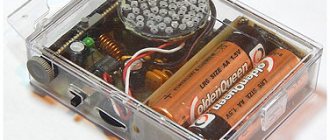
Receiver design
Structurally, the receiver is mounted mounted inside a prefabricated aluminum box measuring 50 x 120 x 240 mm. The lid is made of 2.5 mm thick aluminum, the walls and bottom are made of 1 mm thick aluminum. The bottom can be neglected, but this will somewhat worsen the stability of the receiver. There are eight panels for lamps on the cover (one of them remained unused), an ultrasonic transformer and a variable capacitor are also attached to it.
If you've ever even thought about buying a high-end high-end tube amplifier, the photos below may cause you moral injury.
FM radio receiver on lamps.
Top view The chassis is connected to a common wire; inside there are busbars made of copper wire with a diameter of 2 mm, connected to the chassis and acting as a common wire. Wall-mounted installation. Of course, it was worth adding several stands with contact blades, but I was too lazy.
The installation of the high-frequency part, namely the RF amplifier and the mixer, should be as rigid as possible and made with conductors of minimal length, otherwise the operation of the device will be unstable, which is reflected in frequency drift. The ideal option is to place the HF part in a separate screen.
FM radio receiver on lamps.
View from below. On the front wall there are resistors for adjusting the volume and operating mode of the mixer, and the handle of the variable capacitor is also located there.
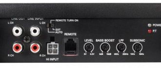
FM radio receiver on lamps. Front view.
The rear wall has connectors for the power supply, speaker and antenna.
FM radio receiver on lamps. Back view.
The power supply is made in a separate case, but this design is not essential. It would be more correct to slightly increase the size of the device and mount the power supply in the same case with it (a 100 W transformer is more than enough). However, this can be considered as a feature: in the twenties of the last century, power supplies were also often made separate.
Radio power supply
The chokes used in the receiver are homemade. The chokes in the filament circuit are wound on 0.25 W resistors with a resistance of more than 100 K and include 150 turns of enameled wire with a diameter of 0.12 mm. The high-frequency chokes are 75 cm (quarter wavelength at 100 MHz) of 0.7 mm diameter enameled wire wound on a 5 mm diameter paper frame. The loop coil contains four turns of enameled wire with a diameter of 2 mm.
Settings
The receiver is quite unpretentious and, if assembled correctly, starts working immediately. However, there are a number of general recommendations for setting it up.
- After switching on, check that the lamps are glowing. If there is no filament, then you should check the serviceability of the lamp or look for an open/short circuit in the filament circuit. The heater filaments of the heated lamp should glow orange.
- The presence of anode voltages should be checked. Some voltages are indicated in the diagram.
- Check the operating mode of the lamps by setting the required voltages in the cathode circuit. If the deviations are significant (more than 50%), appropriate resistors should be selected.
- Check the operation of the ULF: when you touch the resistor motor with your finger, you should hear a characteristic noise in the speaker. It is more difficult to check the operation of the amplifier without an oscilloscope, but if the voltages are set correctly and there are no errors during assembly, it will work.
- Check the operation of the mixer. When you rotate the mixer operating mode control knob at the point where generation begins, noise should appear in the speakers.
- Check the UHF operation: when you touch the antenna input with a screwdriver, characteristic clicks are heard in the speakers.
It is strictly not recommended to touch live circuit elements, as this may result in electric shock! This is dangerous to life and health.
If everything works, then using the mixer mode adjustment knob we get the appearance of noise in the speakers, after which we tune in to the radio station using a variable capacitor. Then, by more precise adjustment of the mixer mode and frequency, we achieve the best reception quality. The setting indicator helps with this. All! You can enjoy warm tube sound. The sound quality of this receiver turned out to be quite good, in any case, it cannot be compared with the sound quality of the super-regenerator.
And finally, the most interesting thing, the reason for which everything was started, is the signal oscillograms at different points of the circuit. I don’t have oscillograms of the mixer’s operation due to the fact that the oscilloscope probes greatly influence its operating mode, so let’s start with the amplifier.
RECOMMENDED: Receiving and decoding signals from space
Let's consider the signal at the input and output of the first stage of the amplifier. The oscillogram of the input (bottom) signal shows that, in addition to the IF signal, high-frequency noise passes from the mixer, and its amplitude is even greater than the amplitude of the desired signal. But this is not a problem, since it will be filtered by the passband of the cascade. Indeed, only the IF signal with an amplitude of about 200 MV is visible in the output signal oscillogram. Please note that the oscillograms have different scales. From these oscillograms you can see that the actual stage gain is about 30 versus the calculated 80.
Signal at the input and output of the first stage of the amplifier
Already at this point, using an oscilloscope, you can see the tuning to the station, which looks like an increase in the amplitude of the signal and a pulsating change in its frequency (frequency modulation).
Frequency modulation of the IF signal
Next, let's look at the operation of the second cascade of the amplifier. Everything is simple and clear here, the input signal is amplified by about 30 times, and at the output we already get about 5 V.
Signal at the input and output of the second stage of the amplifier
After the second stage, the signal enters a limiter, in which it is further amplified and the amplitude is limited at 70 V. Here you can clearly see the suppression of parasitic amplitude modulation and an almost square wave at the output.
Signal at the input and output of the limiter
You can also look at frequency modulation here.
Frequency modulation in the limiter
Now let's take a look at the oscillograms of the counting detector. It can be seen that at each rising edge of the signal, a pulse of approximately the same duration and amplitude is regenerated from the limiter.
Pulses in the counting detector
Frequency modulation is also clearly visible here. For example, changing the frequency of the input signal changes the pulse repetition rate at the detector output.
Pulses in the counting detector
Then the pulses go to an integrating RC circuit, which leads to the formation of a low-frequency output signal. The oscillogram clearly shows the effect of frequency modulation on the output signal.
Generating a sound signal
In total, the operation of the detector looks as shown in the figures below. Here you can see that the audio signal is somewhat delayed relative to the modulated IF, this is due to the integrating RC chain.
Operation of the FM detector
From the detector, the signal goes to the first ultrasonic stage, where it is amplified, and in addition, residual noise from the detector is filtered out.
Operation of the first ultrasonic stage
We can stop there.
Radio reception and transmission: -VHF-
Antenna amplifier for VHF receiver
Low-power VHF transmitter with 2 transistors
Low-power VHF transmitter on the 1st transistor
Miniature VHF radio microphone and receiver
Radio microphone (selection of circuits)
A selection of simple VHF receiver circuits
VHF - converter
Aviation (AIR) band reception
Video modulator
VHF stereo transmitter
Video modulator
Source: A. Ekimov Analog video camera signal modulator. — Radio, 2022, No. 7, pp. 9-10
This device can be used to transmit a video signal to a TV (or, for example, to some models of Chinese cellular phones with a TV receiver) from a video camera installed on the model or, for example, at the entrance to the territory of a private house, when laying an additional wire to the TV is no longer desirable. Due to the fact that analog television has already sunk into the past, such a set-top box will not disturb your neighbors, although you must keep in mind that they can view the signal from your camera if they scan the analog broadcast.
The operating frequency with the parameters indicated in the diagram is 115 MHz, which can be changed within small limits by changing the distance between the turns of coil L1.
The modulator is assembled on a printed circuit board made of double-sided fiberglass, one side serves as a screen. Capacitors C2, C4 and C5 should be used with TKE M47 or MPO; KT368BM transistors can be replaced with transistors of the KT316 series. coil L1 is wound with PEV-2 0.8 wire on a mandrel with a diameter of 5 mm and contains 9 turns. The rest are wound with PEV-2 0.4 wire on a 4 mm mandrel and contain: L2 and L4 - 8 turns, L3 and L6 - 5 turns, L5 - 7 turns. Antenna - copper wire 1.5-2 mm thick, 450 mm long.
When setting up, it is necessary to take into account that if the constant component of the video signal is greater than at the VT2 emitter, its polarity must be changed. The maximum output signal voltage is achieved through trimming capacitors. Resistor R9 is designed to prevent self-excitation of the output stage. If the television receiver is also tuned to the second harmonic (approximately 230 MHz), then the number of turns L4 and L6 should be increased.
Antenna amplifier for VHF receiver
The amplifier circuit is shown in Fig. 1. It is made on a low-noise bipolar transistor. The gain is about 20 dB. At the input of the amplifier, a series-connected low-pass filter (LPF) C1L1C2 with a cutoff frequency of 115 ... 120 MHz and a high-pass filter (HPF) with a cutoff frequency of 60 ... 65 MHz are installed. Thus, the amplifier provides amplification of signals from radio stations operating in both VHF broadcasting bands.
If the amplifier will be installed in a car, then it must be placed in a metal case and power must be supplied through a feed-through capacitor (C9):
The amplifier elements are placed on a printed circuit board made of double-sided foil fiberglass; the pattern of the printed tracks and the arrangement of the elements are shown in Fig. 3. The second side of the printed circuit board is left metallized and connected by foil along the contour to the common conductor of the first side. For the automotive version, the printed circuit board should be extended so that a relay and power filter can be placed.
Fig.3
It is advisable to use a low-noise transistor with a normalized noise figure in the amplifier; the KT3120A indicated in the diagram, as well as KT382A, KT382B, KT399A, KT3101A-2, KT3106A9, are best suited. Capacitors - KD, K10-17 and similar imported ones. S9 - K10P-4, K10-51, KTP, B23. Resistors - MLT. S2-33, P1-4. Coils L1 and L2 are wound with PEV-2 0.4 wire on a mandrel with a diameter of 4 mm and contain 3.5 and 4.5 turns, respectively. Coil L3 is wound on a ring with a diameter of 8-10 mm made of ferrite grade 2000NN and contains 20-30 turns of PEV-2 0.2 wire.
The amplifier is connected between the antenna socket and the radio input. In this case, the connection from the amplifier to the receiver input must be made with a short shielded cable. When installing in a car, all connections should be made with a shielded cable, and the amplifier should be placed near the radio in a shielded compartment. The filters are designed to work on a cable with a characteristic impedance of 50 Ohms. when working on a 75 Ohm cable, it is necessary to reduce the capacitance of capacitors C1-C4 and increase the inductance of coils L1 and L2 by one and a half times.
Setting up an amplifier comes down to setting the required DC mode. By selecting resistor R4, the optimal collector current of the transistor is established, at which the noise figure is minimal. Such modes are usually indicated in the reference book. Then the frequency response of the input filters is checked, and if adjustments are necessary, the turns of the inductors are shifted and moved apart.
When operating the amplifier, it is necessary to ensure that it is turned off in conditions of good reception in order to avoid over-amplification of the signal.
...another circuit is designed to increase the sensitivity of the receiver
If the sensitivity of the VHF receiver is insufficient, it can be equipped with an additional radio frequency amplifier (RFA), assembled according to the diagram shown in the figure. It is better to do it first on a breadboard. In this case, it will be easier, in particular, to select resistor R2 for maximum gain. The current consumption should be within 1.5...2 mA.
An additional RF amplifier is mounted in the receiver with a hinged mounting on the side of the printed conductors.
There is practically no need to set up the RF frequency control; the sensitivity is comparable to a full-size receiver with a whip antenna. Current consumption increases slightly. If the receiver is excited at high volume, it is necessary to connect a capacitor with a capacity of 6800 pF between the input of the variable resistor of the volume control and the common wire.
The amplifier can use transistors of the KT371AM, KT372, KT382, KT391A-2, etc. series.
...amplifier circuit for receivers without RF amplifier
The WA1 loop antenna is made of thick (2...3 mm) copper wire. You can use coaxial cable, which only uses braid. The perimeter of the antenna is about 40 cm, its shape can be round, square, or rectangular. The antenna simultaneously serves as an inductor of the input circuit, which includes capacitors C1, C2.
The circuit is adjusted to the middle frequency of the range using tuning capacitor C1. Together with C2, it forms a capacitive divider that matches the antenna with the input of an amplifier made on microwave transistor VT1. Resistor R1 sets the base bias current, and resistor R2 stabilizes the transistor's DC mode and at the same time is an element of the decoupling circuit R2C3, which prevents the penetration of high-frequency signals into the power source.
The collector circuit of the transistor through the coupling coil L1 includes circuit L2C4, tuned to the middle frequency of the range. The amplified signal comes from the circuit through coupling capacitor C5 to the VHF receiver.
The coils are wound simultaneously, with two PELSHO 0.2-0.3 wires folded together on a frame with a diameter of 5.5 mm with a trimmer. Depending on the band (VHF-1 or VHF-2) and the material of the trimmer (magnetodielectric or brass), the coils should contain 3...5 turns. Since the connection of the circuit with the loop antenna should be minimal to avoid self-excitation of the RF frequency control, it is better to place the coils in the screen.
Another option is to wind the coils on a ring of high-frequency magnetodielectric. A ring made from the central part of half of the SB-1 armored magnetic circuit is suitable. The outer parts are broken off with wire cutters, and the edges of the resulting ring are treated with sandpaper. The number of turns remains the same. Since it is difficult to adjust the inductance of the coil on a ring magnetic circuit, capacitor C4 should be replaced with a trimmer.
A third option is also possible, which almost completely eliminates the danger of self-excitation of the RF amplifier - eliminate the circuit, turning the amplifier into an aperiodic one. Then, instead of coil L1, a resistor with a resistance of 470 Ohms is connected to the collector circuit of the transistor, and capacitor C5 is connected to the collector. The gain in this case will be significantly less and will not exceed several units.
Structurally, the amplifier can be placed either in the receiver itself, or taken out to the antenna; in the first case, the loop antenna must be placed inside the receiver body, if its dimensions allow.
If the amplifier is placed near the antenna, it is more convenient to use a VHF ribbon cable with a characteristic impedance of 240...300 Ohms or a regular telephone cable.
..for car VHF receiver
The amplifier contains a cascade on a low-noise transistor, at the input of which two filters are installed: low-pass filter - L1C1L2 with a cutoff frequency of about 115...120 MHz and high-pass filter - C2L3C3 with a cutoff frequency of about 60 MHz. The maximum gain is approximately 18...20 dB, it can be reduced to 5...6 dB with trimming resistor R5. Through the L4C6L5 low-pass filter, signals with frequencies less than 20 MHz pass from the input to the output of the amplifier. Thus, at these frequencies the amplifier transmits signals with virtually no loss. When the amplifier is turned off (shown in the diagram), the relays are de-energized and the signal from the antenna, through their contacts K1.1 and K2.1, enters the receiver input. The amplifier is powered by a parametric voltage stabilizer assembled on a zener diode VD1; relay windings K1 and K2 are used as ballast resistance. At the same time, a low-pass filter is assembled on these windings and capacitors C8 - C10, which effectively suppresses noise in the power supply circuit. For this purpose, RES-55A relays are used, the resistance of their windings is approximately 67 Ohms, and the inductance is 35...40 mH. It is very important that the winding is placed in a metal screen, which has a separate output. The amplifier is turned on by switch SA1; the dotted line shows the elements for indicating switching on (if necessary). The following parts can be used in the device: transistor - KT382A, KT3101A-2, KT3132A-2, zener diode - KS468A, D814A with a stabilization voltage of no more than 7.5 V, LED - AL307 with any letter index or similar, switch - any small-sized one. Relay RES-55A (version RS4.569.600-08 or RS4.569.600-16). The inductors are wound with PEV-2 0.8 wire on a mandrel with a diameter of 5 mm and contain 3 (L1. L2), 4.5 (L3) and 9.5 turns (L4, L5).
Most of the parts are placed on a printed circuit board (Fig. 2) made of double-sided foil glass-tex-* tolite 1.5 mm thick. The second side is left metallized and connected to the common wire of the first side in several places, and the holes for the terminals of elements that are not connected to the common wire are zenkoana. The board is housed in a metal case, on one of the walls of which there is an XS1 socket, through the same wall there is a cable with an XP1 plug, as well as a power cable, and on the second wall there is a switch and an LED. The XP1 plug is connected to the board with a short piece of RF cable.
The setup comes down to setting the transistor current to a minimum noise figure; this is done by selecting resistor R1. Typically, such data is given in the reference book and for the transistor indicated on the diagram this value is 5 mA. Then they check the performance of the amplifier together with the receiver. The gain is set by resistor R5 when receiving weak radio stations for the best reception quality. It is advisable to set it to the minimum possible.
The L4C6L5 filter does not need to be installed in the amplifier. If the car receiver has only a VHF range, then its absence will not affect the operation of the receiver-amplifier system. If the receiver has the DV, SV or HF ranges, then when operating in these ranges the amplifier must be turned off. Obviously, the amplifier will have a significant effect when used in conjunction with receivers that have low sensitivity. For a receiver with high sensitivity, installing an amplifier will not have a noticeable effect.
Source:
- I. Nechaev, N. Lukyanchikov Antenna amplifier for VHF FM radio receiver. - Radio, 2001, No. 1, p. 16
- G. Voronin Increasing the sensitivity of the receiver. - Radio, 2001, No. 2, p. 19
- V. Polyakov Radio frequency amplifier for VHF receiver. - Radio, 2001, No. 7, p. 58
- I. Nechaev car antenna amplifier of the VHF range. - Radio, 2001, No. 9, p. 17
Radio microphone
..on one transistor (4.5 V power supply)
The radio microphone [1] is assembled according to the classic generator circuit with a capacitive divider in the feedback circuit with the inclusion of the electret microphone B1 directly in the bias circuit of the transistor VT1, which made it possible to get rid of the microphone amplifier, isolation capacitor and varicap. The role of a varicap is performed by the generator transistor VT1 itself, the operating point of which shifts when the conductivity of the microphone changes. The operating range of the device reaches 70 m. Reception can be carried out on a household VHF receiver.
With the values of resistors and capacitors indicated on the circuit diagram, the device operates at a frequency of 87.9 MHz. The frequency is set by stretching or compressing the turns of coil L1. The connection with the antenna is transformer. The WA1 antenna is designed together with a battery container, which increases its efficiency. To ensure that the low internal resistance of the power source does not bypass the oscillatory circuit, inductor L3 is included in the power circuit. The printed circuit board is made of double-sided foil fiberglass 1.5 mm thick, with components placed on both sides. Instead of via holes at the ends of the board, notches are made with a triangular file (indicated by arrows in Fig. 2) in order to lay a thin tinned wire connecting the printed conductors.
In the proposed device, it is desirable to use capacitors SZ, C4, C5 with small TKE. Blocking capacitors C1, C2 are ceramic, of any type. Coil L1 is frameless. It is wound with PEV-2 0.3 wire on a mandrel (an M2.5 screw was used as a mandrel) and contains 8 turns. Coil L2 is wound on top of L1 and contains 2 turns of the same wire. Throttle L3 is ready-made, for example, type DM-0.1. Its inductance is not critical. Transistor VT1 can be replaced with KT368, KT316 with any letter index. The VM1 microphone is of the MKE-369 type or a similar imported one (the deviation of the signal frequency depends on the sensitivity of the microphone). Resistors R1…R3 are MLT-0.125 type. Their leads are removed, the ends are cleaned with a file and tinned for soldering to the board. Power switch SB1 is a small-sized slide switch. Power source G1 - G3 - three AG13 elements for a voltage of 1.5 V. The container for batteries is made of a strip of sheet metal 6 mm wide and 0.2...0.3 mm thick (Fig. 4). The container parts are secured to the printed circuit board by soldering on the corresponding contact pads (Fig. 5).
The entire structure can be mounted into a cylindrical marker body. A hole with a diameter of 2 mm is drilled in its cover opposite the microphone. A groove is cut into the marker body for the power switch.
Another scheme was proposed in [2]:
Coil L1 is etched on the printed circuit board, capacitors C3-C5 must have TKE - P33, MPO, M33, the transistor can be S9014C, KT368, KT399, 2SC9014, S9018 with a collector current transfer coefficient of at least 50.
The setting consists of setting the current consumption to 1.5..2.5 mA by resistor R3. The frequency is changed by selecting C3.
Source:
- S. Kalyuzhny Radio microphone. - Radio, 2001, No. 11, pp. 57-58
- P. Tarasov Radio microphone. — Radio, 2012, No. 1, p. 54
..on 2 transistors (power supply 1.5V)
The device is designed to operate at a frequency of 87.9 MHz, communication range up to 40m.
On VT1 (any of the KT315 series) a microphone amplifier is assembled, on VT2 (you can also use KT368A, KT355A) - an HF generator.
Antenna - a piece of wire with a diameter of 1-2 mm and a length of 15-30 cm. Coil L1 - 5 turns PEV-1 0.5 on a frame with a diameter of 5 mm. Microphone MKE-3, but you can use any electret with two terminals; for this, the positive terminal C1, the lower terminal R1 in the diagram and one of the microphone terminals are connected together.
Source: I. Kutsko Radio microphone. - Radio, 2001, No. 6, p. 57
Miniature VHF radio microphone and receiver
The radio microphone (Fig. 1) is a single-stage micro-power transmitter with frequency modulation, operating at a frequency of 87.9 MHz of the VHF broadcasting range, specially designated for radio microphones. Its signal is received by any VHF radio broadcast receivers; the range does not exceed several tens of meters.
Inductor L3 and capacitor C1 form the oscillatory circuit of the generator. It is included in the collector circuit of transistor VT1. The positive feedback signal necessary to excite oscillations is created by coil L4 and is supplied to the base of the transistor through capacitor C4.
The second transistor (VT2) serves to amplify the AF oscillations picked up from the microphone. From resistor R2, the amplified AF signal is supplied through resistor R1 to the base of generator transistor VT1. Since there is a positive voltage at the collector of transistor VT2 relative to the common wire, resistor R1 also sets the bias current to the base of transistor VT1, bringing it to the linear portion of the characteristic.
With this modulation method, the capacitances of the transitions and the delay in the passage of the high-frequency signal through the transistor change, and this leads, first of all, to a change in the oscillation frequency, and secondly, to their amplitude. For such a primitive method of frequency modulation, it is necessary that the cutoff frequency of the transistor is not much higher than the operating frequency. If you use a good high-frequency transistor, weakly connected to the circuit, no significant frequency modulation will be achieved.
The antenna of the radio microphone is the electret microphone VM1 itself and the wires suitable for it - they are connected to coils L1 and L2, which have a strong connection with the loop coil L3. For high frequencies, the coils seem to be one, on the lower output of which there is no high-frequency voltage, and on the upper one, connected to the collector of transistor VT1, the maximum high-frequency voltage develops. It excites all three wires, folded in parallel.
The coils are wound on one frame with a diameter of 5.5 mm, inside of which there is a brass trimmer with an M4 thread. Coils are made like this: put together three PELSHO wires with a diameter of 0.2...0.3 mm and wind them into four turns so that a continuous single-layer winding is obtained. The terminals are secured with thread and (or) glue. A communication coil L4 containing two turns of the same wire is wound over the winding.
The design of the radio microphone is shown in Fig. 2. The entire device is assembled inside a plastic tube of such a diameter that it includes a microphone and a battery. Transistors, coils and other parts, together with the power switch, are mounted on a small board, preferably a printed circuit board, which is placed at the bottom of the tube above the battery. The three microphone leads are extended with conductors about 30 cm long to increase the effective length of the antenna. The microphone itself serves as a small capacitive load. The conductors are rolled into a loose spiral and placed inside the tube.
The battery is inserted from below and covered with a polyethylene cover, on which there is an elastic contact (spring) of the negative terminal. The conductor from it passes to the common wire of the board along the element. The positive terminal contact is soldered to the SA1 switch terminal. Thus, the battery serves as a second capacitive load, already a counterweight, which, like the microphone, increases the efficiency of such a short antenna. The counterweight antenna forms something like a Hertzian dipole, completely hidden inside the housing.
Miniature receivers operating on headphones can be conveniently built on the basis of the KXA058 microcircuit. The receiver circuit is shown in Fig. 3. Blocking capacitor SZ stabilizes the operation of the receiver when the battery is very discharged.
The receiver current consumption is 10...14mA. The antenna is telescopic, about 30 cm long, you can use a piece of wire.
The receiver coils are wound on frames with a diameter of 5.5 mm made of plastic or organic glass. The frames have an M4 thread. The coil of the input circuit L1 is adjusted with a brass trimmer with the same thread; it contains six turns of PEL 0.3 wire. The receiver is tuned to the frequency of the radio microphone by changing the inductance of the heterodyne circuit L2. For this purpose, a brass M4 screw is screwed into the frame, extended by a plastic extension with an adjustment knob brought out through the end wall of the receiver housing. Local coil L2 contains four turns of the same wire.
The output voltage of the AF at pin 15 of the microcircuit reaches 0.1...0.2 V at peaks. This is quite enough for the operation of phones, but the AF current needs to be increased. This purpose is served by a composite emitter follower assembled on transistors VT1 and VT2. The operating mode of the transistors is set by the bias resistor R2. Its resistance should be such that the transistor current does not exceed 3...5 mA. Resistor R3 is current-limiting; it does not allow too much current to flow if the phone terminals are accidentally shorted, for example, when they are turned off. It is also useful to select its resistance according to the best sound of the phones used. They can be either high-resistance or low-resistance.
Source: V. Polyakov Radio microphone. - Radio, 2001, No. 9, pp. 52-53
Low-power VHF transmitter with 2 transistors
The device is intended for broadcasting (in the VHF range) within a small room a signal from the linear output of any sound source.
The transmitter is an asymmetrical multivibrator with a frequency-setting circuit L1C1; a distinctive feature of this circuit design is the ability to operate at high frequencies at very low currents and voltages.
One 1.5V element is used as a power source. The direct current through the transistors is set by resistors R3, R4. A change in this current leads to a slight change in the frequency of the generated oscillations, therefore, to obtain frequency modulation, a modulating AF voltage from the signal source is supplied to the current-setting circuit from resistor R1 through capacitor C1 and resistor R2. The amount of deviation is controlled by variable resistor R1.
The transmitter power is about 1 mW, which is enough for reliable signal reception within the room. With a supply voltage of 1.5V, the current consumption is 0.42 mA. Operation is maintained when the power supply voltage decreases to 0.8V.
A piece of copper wire with a diameter of about 1 mm and a length of 20-100 cm is used as an antenna. Coil L1 contains seven turns of PEV-2 0.8 wire, wound on a 3.5 mm mandrel with a tap from the middle.
The transmitter is assembled on a board made of double-sided fiberglass, with the parts placed on one side, and the other side connected to a common wire in several places.
Set up the transmitter in the following sequence. First, the receiver selects the range that is most free from broadcast stations. Connect the transmitter to the output of the sound-reproducing device and use capacitor C4 to adjust the frequency until reliable reception. Then resistor R1 selects an acceptable deviation frequency.
Literature:
Nechaev I. Sound accompaniment without wires. - Radio, 1998, No. 10 p. 50
Low-power VHF transmitter on the 1st transistor
The transmitter input can be connected to the linear output, as well as the headphone output of any sound-reproducing device. The variable resistor R1 regulates the modulation level, and therefore the sound volume and its quality. The RF generator, assembled on a transistor, produces oscillations with a frequency of about 100 MHz, which depends on the parameters of the L1C4 circuit.
Through the communication coil L2, modulated (frequency) oscillations enter the antenna WA1 - a short piece of wire (15...20 cm), if the receiver is located close.
In addition to the transistor indicated in the diagram, you can use KT306G, KT306D or other low-power microwave p-p-p or p-p-p structures (in this case, you need to change the polarity of the power source). Fixed resistors - MLT-0.125, variable - any small-sized, capacitors KM-b (C2), K53-14 (C6), KLS, KT (others). The coils are wound with PEV or PEL wire on a frame with a diameter of 7 and a length of 10 ... 12 mm, glued together from cardboard or thick paper. Coil L1 should contain 6 turns, L2 - 3 turns. Place the coils nearby. The parts of the radio transmitter are mounted in a small housing, either mounted or on a printed circuit board.
Device circuit board
Another transmitter circuit using a single transistor at a frequency of 87.9 is shown in the figure below:
Using transformer T1, in accordance with the AF input signal supplied to winding I, the supply voltage of the generator changes, which leads to a change in the capacitance of the p-n junctions of the transistor - FM is carried out.
The loop antenna - coil L1 - is a coil of copper tube with a diameter of 4 and a length of 260 mm, to the ends of which a tuning capacitor is soldered. Instead of a tube, you can use a piece of copper wire of the same length and, if possible, a large diameter.
Trimmer capacitor with capacitance varying from 8 to 30 pF. It is permissible to replace it with a constant capacitance capacitor, having previously determined the required capacitance during setup.
Transformer - any small-sized matching device from an industrial “pocket” radio receiver. It is turned on “in reverse”: winding I is half low-resistance, II is high-resistance. Transistor - any low-power high-frequency transistor, for example, P403, P416, GT313, KT361 series.
When setting up the device, a milliammeter with a measurement range of several tens of milliamps is included in the power circuit. Periodically touching the collector of the transistor with a screwdriver, observe the decrease and increase in current (disruption and generation). If this does not happen, you need to select resistor R1.
Next, connect the device to the TV, tune the radio receiver to a frequency of 87.9 MHz and use the tuning capacitor C3 to achieve signal reception. Then, by changing the connection of parts of the transformer windings, they achieve the best sound (without distortion) in headphones with the TV volume control in the middle position. The frequency deviation, which is smoothly varied with the volume control, depends on the ratio of the number of turns of the transformer windings.
Source:
- Petrosyan E. Player for two. - Radio, 1999, No. 10, p. 51
- O. Bobrov Sound accompaniment on the radio. - Radio, 2001, No. 7, p. 56
A selection of simple VHF receiver circuits
..radio 1994№8 1995№10 1996№10
Source:
- A. Zakharov VHF FM receivers with PLL. - Radio, 1985, No. 12, pp. 28-30
- D. Alekseev Simple VHF FM receiver. - Radio, 1990, No. 11, p. 48
- Designs by O. Bobrov. - Radio, 2001, No. 3, p. 54
..on 3 transistors [2]
With the parameters of the circuit parts included in the receiver, the receiver is designed for the range of 65..73 MHz. The output power of the amplifier at a load of 8 ohms is 3 mW, current consumption is 10 mA.
Coils L1 and L2 are frameless, internal diameter 5 mm, pitch 2 mm. Coil L1 contains 6 turns with a tap from the middle, L2 - 20 turns (PEV-2 wire 0.56). Coils L3 and L4 each contain 200 turns of PEL 0.06 wire. They are wound on a ferrite rod M400NN with a diameter of 2 and a length of 10 mm in 2 wires.
It is better to use KT3102B as transistor VT1.
The setup begins by setting the mode of transistors VT2-VT3 by selecting resistor R5 (collector current VT3 should be 6..9 mA). The local oscillator mode is regulated by selecting resistor R1, the level of the second harmonic is controlled by capacitor C6. The boundaries of the received range are set by changing the inductance L2. The receiver is tuned according to the range using capacitor C7.
..VHF FM set-top box [3]
Together with an AF amplifier, this set-top box will turn into a radio receiver operating in the VHF FM range.
The attachment is a frequency converter with a combined local oscillator, which simultaneously performs the functions of a synchronous detector. The broadcast station signal received by antenna WA1 is fed to the input circuit L1C2, tuned to the middle frequency of the VHF range (70 MHz), and from the circuit to the base of the transistor VT1 (through capacitor C4).
As a local oscillator, the transistor is connected according to a circuit with a common base, and as a frequency converter - according to a circuit with a common emitter.
The local oscillator operates at a frequency of about 35 MHz, the second harmonic frequency is 70 MHz. The L2C5 circuit is tuned to a frequency half that of the input circuit, and since the conversion occurs at the second harmonic of the local oscillator, the difference frequency turns out to be in the AF range. The AF signal is amplified by the same transistor, which is connected as a synchronous detector according to a circuit with a common base. From terminals X3 and X4, the AF signal is fed to an amplifier, the sensitivity of which must be no worse than 10 mV (the output signal of the set-top box can be within 10...50 mV depending on the field strength).
The coils are frameless, their internal diameter is 5 mm, the winding pitch is 2 mm. Coil L1 contains 6 turns of PEV-2 0.56 wire with a tap from the middle, L2 - 20 turns of the same wire.
An antenna is a piece of copper wire, the length of which is selected experimentally for the best reception quality. Trimmer capacitors - KPK-1. Power supply voltage 1.5 V.
Set up the set-top box with a connected AF amplifier like this. First, tune it to the radio station by changing the inductance of the coil L2 (stretching or compressing its turns) and the capacitance of the capacitor C5. Then, by adjusting the input circuit - stretching and compressing the coil turns, as well as changing the capacitance of capacitor C2 - the maximum sound volume is achieved.
..on the K174PS1 chip
The presented VHF radio receiver uses an industrial module of an intermediate frequency audio amplifier for television receivers (UPChZ-1) with an intermediate frequency of 6.5 MHz, the frequency detector and filters of which do not require adjustment. The K174PS1 microcircuit was used as a mixer.
The signal from antenna WA1 through capacitor C1 is supplied to input circuit L1C2, tuned to the middle of the received range (100 ... 108 MHz). The low quality factor of the input circuit (about 10) allows you to cover the entire range without tuning it, however, due to the high intermediate frequency, noise suppression of the mirror channel is ensured.
The isolated signal is fed through capacitor C4 to the input of the mixer. Its role is played by a balanced multiplier on the DA1 chip. The local oscillator signal is supplied to the second input of the mixer through capacitor C8. The local oscillator is assembled on transistors VT1, VT2 according to a multivibrator circuit loaded with a resonant circuit. The local oscillator frequency is determined by the L3C9VD2 circuit and is adjusted by changing the reverse voltage on the varicap using resistor R3. This design ensures stable operation of the local oscillator together with the mixer. The supply voltage of the mixer and local oscillator is stabilized by VD1R4.
The load of the mixer is circuit L2C7, tuned to an intermediate frequency (6.5 MHz). Through capacitor C10, the intermediate frequency signal is fed to the input of module A1 (UPChZ-1), where the FM signal is amplified and detected. From the output of the detector, through a variable resistor R5, which serves as a volume control, an audio frequency signal is supplied to the input of the ultrasonic sounder, assembled on the K174UN7 microcircuit.
The receiver can use the K174PS4 microcircuit, UPChZ-1 can be replaced with UPChZ-2, and the K174UN7 microcircuit can be replaced with any other one with the function of an audio frequency power amplifier. If necessary, the UMZCH can be assembled according to any other scheme. Transistors - KT361 series with any letter index. Coils L1 and L3 are frameless, wound with wire with a diameter of 0.8 mm on a mandrel with a diameter of 4 mm and contain 10 turns each. Coil L2 is wound on a unified frame with a ferrite trimmer from an intermediate frequency filter of a mid-wave superheterodyne radio receiver and contains 20 turns of wire with a diameter of 0.15 mm.
Setting up the VHF receiver begins with checking the functionality of the UMZCH. The operation of the local oscillator is monitored by connecting a voltmeter to the connection point of the emitters VT1 and VT2. When you touch the L3C9 circuit with your finger, the voltmeter readings should change, which indicates that the local oscillator is working.
Next, by changing the capacitance of capacitor C9, you need to tune in to a radio station. By rotating the L2 coil trimmer, the best sound quality is achieved. By compressing or stretching the turns of coil L3 and changing the capacitance of tuning capacitor C9, the required range overlap is achieved.
The adjustment process ends by adjusting the input circuit L1C2 to the maximum sensitivity of the receiver.
Source: Yu. Arakelov Simple VHF FM receiver. - Radio, 2001, No. 5, p. 15
..on the KR174XA34A (AM) chip
The KR174XA34 microcircuit (analogous to TDA7021) is a specialized microcircuit for operation in VHF receivers, which is a superheterodyne radio receiving device.
A typical connection of the microcircuit is shown in the figure: