Hello, dear readers of the site. Being in nature, it is not always convenient to listen to your favorite radio station or get the latest news using your cell phone. If you listen with headphones, you will be tied to the phone all the time and cut off from the world around you, but if you use the phone’s speaker, the battery charge will last for 2-3 hours. VHF receiver can help get rid of these inconveniences .
Such a receiver can be purchased in a store, or you can make it yourself, and the price will be two to three times cheaper than a store-bought one. We present to your attention the design of a homemade small-sized VHF receiver , which provides reliable reception of radio stations broadcasting in the range of 88 - 108 MHz.
The proposed design is easy to manufacture and set up, and its small dimensions and fairly high technical characteristics allow the receiver to be used both in the city and when traveling outside the city. This receiver can be assembled even by a novice radio amateur taking his first steps into the world of radio electronics.
The receiver has the following parameters:
sensitivity from the antenna input – no less than 5 µV; output power at a load of 8 ohms - about 0.2 W; supply voltage – 3V; quiescent current – 12…14 mA; current at maximum volume – no more than 25 mA; frequency band – 450…7150 Hz; harmonic coefficient – 0.1%. The receiver remains operational at a voltage of 2 V; Continuous operation of the receiver is 80...90 hours.
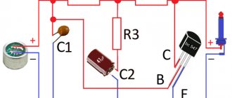
Schematic diagram of a VHF receiver.
The receiver is based on the K174XA34
(DA1), designed for operation in low-voltage mono and stereo radio broadcast receiving devices in the VHF-1 and VHF-2 bands. It is a ready-made superheterodyne VHF receiver containing all the components necessary for receiving and processing broadcast signals - from the antenna input to the audio frequency signal output.
From antenna WA1
the received signal from radio stations is supplied to the input oscillating circuit
L2
,
C13
,
C16
, tuned to the middle of the received range 88 - 108 MHz, and from the circuit it is supplied to the input of the microcircuit (pins 12, 13).
L1 is connected to the other input of the microcircuit (pins 4, 5)
,
C2
,
VD4
.
By changing the resonant frequency of this circuit, the receiver is tuned to the desired radio station, where the tuning element is the varicap VD4
.
The capacitance of the varicap is changed by a constant tuning voltage taken from the variable resistor R3
.
The tuning voltage is well stabilized and practically independent of the power source voltage in the range of 1.8...3 V. Stabilization is necessary so that when the batteries are discharged, the tuning frequency of the receiver does not shift. Current stabilization is performed on VT1
,
R1
,
R4
,
R5
,
VD1 - VD3
.
All other signal processing - mixing, detection, pre-amplification of the audio signal is carried out by the microcircuit.
Processed low-frequency station signal from output 14
The microcircuit, through resistor
R7
and constant capacitor
C12,
goes to the upper terminal of variable resistor
R8
, which acts as a volume control.
From the variable resistor motor, the signal is fed to the input of an ultrasonic receiver, made on a low-voltage power amplifier K174UN31
(DA2), specially designed for operation in small-sized equipment.
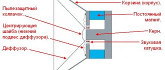
The BA1
dynamic head is connected to the ultrasonic sound output via an electrolytic capacitor C20 .
The receiver is powered by two AA batteries connected in series. Normal operation of the receiver is maintained when the supply voltage is reduced to 1.9 V. This is due to the operation of the K174XA34 microcircuit.
The receiver, assembled without errors and in working order, starts working immediately. The whole setup consists only of adjusting the inductance of the coils of the input and heterodyne circuits.
Scheme
We have already discussed the block diagram of a superheterodyne up and down and even found out why it is “super”. Here everything will be approximately the same: UHF, mixer, amplifier, detector, ULF. Below is a diagram of the VHF unit and the IF.
VHF unit and amplifier
VHF unit
Historically, in tube receivers the UHF mixer and local oscillator were made as a separate unit. This is due to the fact that the VHF part of the receiver needed careful shielding and required better installation, so it was more convenient for industry.
In addition, a number of specific circuit solutions were used there aimed at suppressing spurious radiation into the antenna. In our case, everything is simpler, since we use a synthesizer as a local oscillator.
The amplifier and converter are assembled on a 6N3P lamp; industrial VHF units are usually assembled on it. The use of triodes is due to their low noise level; instead of a 6N3P lamp, you can use a 6N23P or, at worst, another double triode. There are examples of using 6N1P and even 6N2P on the network.
The synthesizer output is 50 ohm, so it is convenient to feed its signal into the cathode circuit. To do this, the auto-bias cathode resistance is divided into two parts - 47 Ohms for connecting the synthesizer and 1 kOhm to provide the necessary bias.
The upper part of the divider is bypassed by a capacitor. The restructuring of the inverter circuit is carried out using a BB910 varicap. The circuit coil is frameless, wound with a wire with a diameter of 1.5 mm on a mandrel with a diameter of 12 mm and contains four turns. The IF output circuit serves to isolate the IF frequency and match the resistance with the ceramic filter. The contour coil contains twenty turns of wire with a diameter of 0.2 mm, the communication coil is wound on top of the contour coil and contains ten turns of the same wire.
In the converter, to receive the required signal, it is theoretically possible to use two local oscillator frequencies, above the signal by the IF value and below by the IF frequency. In this case, injection from below works much more efficiently, so we will use it. When receiving a powerful station, the output of the converter produces a signal of several millivolts.
The installation of the high-frequency part is as follows.
Installation of high frequency part
HRC
The amplifier is the main unit of the receiver. Most of the characteristics are determined by the HRC. And in the case of an FM receiver, conflicting requirements are placed on the amplifier. On the one hand, you need a bandwidth of about 300 kHz, and on the other hand, you need fairly steep frequency response slopes.
Classically, this problem was solved by distributed selection circuits, where in each stage there was a bandpass filter consisting of two loosely coupled circuits, and this is the best option. However, it turned out that creating such a filter using the frames I had was quite difficult. And the main problem here is the adjustment of the connection between the circuits, which greatly affects the frequency response. Actually, due to the problem with smooth control of communication, I abandoned this solution in favor of a scheme with concentrated selection, which is considered a more modern solution. More specifically, we will put a 10.7 MHz ceramic filter at the input of the amplifier. With this we will solve the problem of the steepness of the frequency response slopes and immediately obtain the required selectivity in the adjacent channel.
Unfortunately, the ceramic filter has a low input impedance, so it must be matched to the output impedance of the frequency converter. To do this, we use inductive coupling with the output circuit of the converter. There are no problems with matching the output impedance. Of course, a ceramic filter has an imperfect frequency response and a fairly large signal attenuation, but this is a small price to pay for simplicity.
A circuit with single circuits is not the best solution, but it is quite workable. Another problem is related to the amplifier's tendency to self-excite, especially with regard to the amplifier presented above. Because of this unpleasant feature, even when self-excitation was not observed, the frequency response of the amplifier changed depending on the warm-up and strength of the input signal (the gain increased, but the band narrowed). And this was all reflected in the sound.
This was treated by careful tuning in a warm state. Therefore, I abandoned the capacitively coupled circuit, and the final modification contains an inductively coupled amplifier. It produces slightly lower gain, but it is much more stable in operation.
Inductive coupling amplifier circuit
Actually, the fundamental problem with building a tube amplifier according to a concentrated selection scheme is that at frequencies above a couple of megahertz, non-resonant (aperiodic) tube amplifiers do not work. And that is why we did not have such a problem when building a receiver with a low IF. There we, without further ado, used aperiodic cascades.
This number won't work here, so you won't be able to get away from the contours. The easiest way is to assemble a resonant amplifier using pentodes; this will allow us not to encounter the peculiarities of triodes at high frequencies. A simplified formula for calculating the gain of a resonant cascade on a pentode looks like
K = SrQ
where S is the transconductance of the lamp (MA/V), r is the characteristic resistance of the circuit, Q is the quality factor of the circuit.
The actually measured gain is noticeably lower than this expression predicts. But for our estimates, we will limit ourselves to only this formula, from which it is obvious that it is better to take a lamp with a higher slope and a higher characteristic resistance. But with the quality factor it is more difficult, since as the quality factor increases, the bandwidth decreases, so a high quality factor will only hinder us. However, it can be reduced by bridging the circuit with a resistor, or by using mutually detuned circuits.
As a result, after a series of experiments, I came to an IF circuit coil containing 45 turns of 0.12 mm wire and a 10 pF circuit capacitor. The characteristic resistance of such a circuit is about 700 Ohms, and when it is shunted with a 15 K resistor, the quality factor is about 10. With such a circuit, from one stage on a 6AU6 (6Zh4P) lamp you can get a gain of about 20 and a bandwidth of about 1 MHz.
This is for a capacitively coupled amplifier. In an amplifier with inductive coupling, the coil is wound in two wires and its inductance turns out to be less for the same number of turns (here we are limited by the dimensions of the frame). Therefore, loop capacitors are already required at 33 R, and the characteristic resistance is about 400 Ohms. The gain of such a cascade is about 12.
The IFC uses Japanese 6AU6 lamps from NEC, but they can be easily replaced with our 6Zh4P. Similar results can be achieved with lamps 6Zh1P, 6Zh1B, 6K4P, 6Zh5P, a little worse with 6Zh2P, but you need to select the ratings of the parts in order to set the passport mode.
If you take a cooler lamp, such as 6Zh52P, you can increase the gain of the cascade to a hundred, but it came into my hands too late, and it eats electricity like three 6AU6s. I didn’t bother with the AGC either, especially considering the modest gain of the amplifier, but the limiter would be very useful.
Limiter and Fractional Detector
A fractional detector is quite a tricky thing, and it’s impossible to simply explain its operation with fingers. But this very principle is based on changing the phase of oscillations in two connected circuits. So, when tuning to resonance in the second circuit, the phase is shifted by 90°, and when detuned, the phase shift changes up or down depending on the frequency.
Thus, by adding the original (in-phase) signal with a signal shifted in phase by an angle proportional to the change in the frequency of the original signal, we move from frequency modulation to amplitude modulation. And the rest of the scheme is a matter of specific implementation. You can read more about this here or here.
The frequency discriminator and fractional detector operate on this principle. The fractional detector has some advantage in that it is less sensitive to spurious amplitude modulation. This is exactly what I used in the receiver. The figure below shows a diagram of a limiter and a fractional detector.
Fractional detector and limiter
Generally speaking, a limiter for a fractional detector is not necessary, but it works better. Structurally, the detector is made in the form of a separate block and is entirely placed in a screen, which has holes for adjusting the contours. Most of the parts are SMD-made, which helped reduce the dimensions.
The detector is almost assembled
Detector board
Screen
The coils are made on the previously mentioned L4 cores and contain 20 turns of 0.2 mm enameled wire. Coil L5 is wound on top of L4 and contains five turns of the same wire. Coil L6 is wound on a separate frame with a double wire and contains 12 + 12 turns. The frames themselves are placed at a distance of 10 mm from each other.
1N34 diodes can be replaced with more authentic D2 or D9. Oddly enough, despite my expectations, there were no problems in setting up the fractional detector; the main thing was to get into the desired frequency range, which was solved by selecting capacitors C6 and C7.
As for the limiter, it comes from a conventional amplifier stage with a reduced voltage on the accelerating electrode and a low anode current, which limits the amplitude in the anode circuit. In addition, the cascade operates without bias and somewhat limits the amplitude of the input signal due to the grid current.
Ultrasound and power supply
The audio amplifier is made according to a completely typical single-ended circuit using a 6F5P lamp and completely replicates the ultrasonic frequency of the previously mentioned receiver with a low IF. There is probably nothing more to discuss here; there is even more information on the Internet on the topic of tube single-ended amplifiers than is necessary. The only thing worth mentioning is grounding the filament circuit through resistors: this solution allows you to suppress a background of 50 Hz.
UZCH and BP
The power supply is made on a TAN-3 transformer, the circuit is completely typical.
Details.
Resistors.
The receiver uses fixed resistors with a power of 0.25 - 0.125 W, domestic and imported. Variable resistor R3 is type SP3-36, and resistor R8 is type SP3-3 or any imported one of suitable size.
Capacitors.
Any small-sized permanent capacitors. Oxide capacitors should be rated at less than 6 Volts. A slight variation in capacitor capacitances compared to those indicated in the diagram is allowed.
Reels.
Coils L1 and L2 are frameless. They are wound turn to turn on a cylindrical mandrel with an outer diameter of 4.5 and 5 mm. Coil L1 has 3 turns, an internal diameter of 4.5 mm and is wound with PEV-1 0.5 wire (wire cross-section 0.5 mm). Coil L2 has 7 turns, an internal diameter of 5 mm and is wound with PEV-1 0.9 wire (wire cross-section 0.9 mm).
After winding, coil L1 must be stretched to a length of 4...5mm, and L2 to a length of 7...10mm. And in the future, when both coils are soldered on the board, then in order to reliably receive radio stations, their length will have to be slightly adjusted to increase or decrease the inductance.
Diodes.
Diodes VD2 and VD3 must be silicon from the KD521A, B or KD522A, B series. The use of other diodes is undesirable, as this will increase the minimum voltage of the stabilizer and will require the selection of compensating resistor R1.
Transistors.
Transistor VT1 is any of the KT3102 series.
Simple VHF FM radio receiver
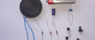
I thought about introducing my youngest child to amateur radio, perhaps not the most interesting topic today for an 11-year-old child, but still better than sitting on YouTube or something worse. I pre-ordered a small (completely) kit for self-assembly, here’s the bug:
After successful assembly, the child caught fire, it was interesting, and we began to make plans for what to do next.
— the first step was to attach a solar panel to this beetle and teach it how to do its work during the day.
— the second point is to switch the beetle’s power supply to lithium with charge control from the same solar battery:
Well, this is all a saying and half measures. Of course, it’s worth thinking about fully assembling something. that will rustle and make some sounds, and as everyone guessed from the title of the article - it will be a receiver. Most radio amateurs began their hobby by assembling a radio receiver and I was no exception, so I decided not to invent anything new, but to follow the same path. And this article is a selection of diagrams and information for the upcoming work, a task plan, so to speak.
1 scheme:
Receiver with one transistor. The antenna works with a piece of mounting wire 15-20 centimeters long, or if the receiver will be assembled into a stationary housing, you can use a telescopic one from any receiver. From the antenna, the signal enters the oscillating circuit L1C2, by adjusting the capacitor C2, the circuit can be tuned within the VHF FM range 65.8-73 MHz. By changing the data of the coil L1, you can tune it all to another range: 88-108 MHz. The signal isolated by this circuit is supplied through capacitor C3 to the base of transistor VT1. This transistor stage performs several functions simultaneously: the functions of a phase detector, a low-pass filter, a DC amplifier and a low-frequency amplifier
(Here the diagram is not very good for a beginner, it is easy to assemble, but combining all the functions about one element can be VERY difficult to understand!!!).
Details:
- The L1 coil does not have a frame; for winding, the shank of a drill with a diameter of 7 mm is taken and the coil is wound on it with PEV wire 0.4...0.5 mm. Coil L1 contains 14 turns. After winding, the drill is removed from the spool (it serves only as a mandrel for winding).
- The P416B transistor can be replaced with GT308A, KT603B (and here comes the second question: choosing an analogue, 2N2222 or 2N2219 suggests itself, which is much better, but also more expensive).
- Telephone – any high-impedance small-sized one.
- Capacitor C2 type KPK is ceramic, 8...30p, 5...20p or 4...15p, it is adjusted by rotating the screw located in the middle.
- As a power source, you can use a 9 V Krona battery. Any switch, for example a toggle switch.
Setup is relatively simple.
You need to connect the phone, power and antenna - a piece of mounting wire, the longer the better. It is advisable to hang the antenna out the window or hang it on the window frame. Now you need to put on your headphones (there should be a slight hiss in them) and try to catch one station by rotating the rotor of capacitor C2. If this does not work, you need to stretch the coil turns a little and repeat. 2 scheme:
It is not particularly different from the first one, it has the same disadvantages and advantages, but it also requires a ULF.
The setting is ensured by changing the capacitance C2 or C7. Also, the tuning frequency is affected by inductances L1, L2, and any parasitic installation capacitances. Even if you raise your hand, the frequency will be lost. Therefore, such a receiver must be well shielded. Details. It is better to use a low-power ultra-high-frequency transistor VT1, for example, KT368. For the VHF range, coils L1 and L2 have 6 turns with a tap from the middle and 20 turns of PEV-2 0.56 wire, respectively. The coils are frameless, with an internal diameter of 5 mm. For the FM range, you can try reducing the number of turns of both coils in half. But it is better to select the number of turns experimentally. The antenna is telescopic or a piece of copper wire about a meter long.
3 scheme:
The circuit is partly devoid of many of the disadvantages of previous circuits, but is not so easy to assemble - there are 3 transistors, not one).
The receiver is made according to a direct conversion circuit with a PLL. The radio frequency stage of the receiver is assembled on transistor VT1 and is a frequency converter with a combined local oscillator, which simultaneously performs the functions of a synchronous detector (again, the same problem as in the first 2 options). The receiver antenna is the headphone wire. The signal from the broadcasting station received by it is sent to input circuit L2, tuned to the average frequency of the received VHF range (70 MHz) and then to the base of transistor VT1. As a local oscillator, this transistor is connected according to the OB circuit, and as a frequency converter - according to the OE circuit. The local oscillator is tunable in the frequency range 32.9...36.5 MHz, so that the frequency of its second harmonic lies within the boundaries of the VHF broadcasting range (65.8...73 MHz). The L2C5 circuit is tuned to a frequency half that of the L2 input circuit, and since the conversion occurs at the second harmonic of the local oscillator, the difference frequency appears to lie in the audio frequency range.
The difference frequency signal is amplified by the same transistor VT1, which, like a synchronous detector, is connected according to the OB circuit. The receiver's AF amplifier is two-stage. The pre-amplification stage is made on transistor VT2, and the power amplification stage is made on transistor VT3. Listen to received transmissions on the headphone BF1 (TM-4). The output power of the AF amplifier on a load with a resistance of 8 0m when powered by one A332 element (1.5 V) is about 3 mW, which is quite enough to work with a headphone. The current consumed by the receiver from the power source does not exceed 10 mA. The receiver can be assembled in any small-sized housing. Wall-mounted installation. Resistors - MLT-0.125, oxide capacitors - K50-6, trimmers - any with an air dielectric, the rest are KM, KLS,
Coils L1 and L2 are frameless. The inner diameter of the winding is 5 mm, the winding pitch is 2 mm, Coil L1 contains 6 (with a tap from the middle), and L2 – 20 turns of PEV-2 wire 0.56, Coils L3, L4 each contain 200 turns of PEL wire 0.06 . They are wound on a ferrite (M400NN) rod with a diameter of 2 and a length of 10 mm into two wires. Transistor VT1 can be replaced with KT3102B, and the sensitivity of the receiver will increase. Setting up the receiver begins with the AF amplifier. The operating mode of transistors VT2, VT3 is set by selecting resistor R5 until the collector quiescent current of transistor VT3 is equal to 6...9 mA. The local oscillator mode is regulated by selecting resistor R1, the level of the second harmonic of the local oscillator is controlled by capacitor C6. The boundaries of the received frequency range are set by changing the inductance of coil L2. The input circuit is adjusted with capacitor C2, focusing on the maximum retention band of signals from received radio stations. The receiver is tuned according to the range using capacitor C7.
(Full description of the scheme: Nikolaev A.P., Malkina M.V. “500 schemes for radio amateurs”)
I stopped my research here because a complete FM receiver will be complex or it needs to be built on a specialized chip, for example on a TA2003 (this is probably the best example), but I think this is the best option for a beginner, it will certainly work. but there will be no understanding of what and why.
By the way, there is a good receiver designer for the TA2003 with a digital scale. It is good not only for its characteristics, but also because the digital scale module is built on a separate board and can be easily converted into a frequency meter.
Here is the diagram of this receiver:
I will raise the issue of building a frequency meter on such a block again, and we will probably move the construction of the receiver with my child towards the AM receiver...
I'd love to hear your comments and advice!
How to make a tube radio
With the advent of transistors and integrated circuits, tube designs were forgotten for some time. Nowadays, radio amateurs are increasingly turning to vacuum tubes in their designs. A homemade VHF tube radio receiver can be assembled using one lamp. The circuit uses the super-regenerator principle. Such devices use a small number of radio components. They are highly sensitive. The disadvantage of super-regenerative receivers is noise in the speakers in the absence of a useful signal.
The VHF receiver is assembled on a 6Zh5P finger pentode. A bridge rectifier is used as a power source, providing 100-120 V DC voltage. All capacitors, except the transition capacitor, are ceramic. Coil L contains 4 turns of copper wire with a diameter of 1 mm. It is best to use silver-plated or tinned wire. Typically, lamp filaments are powered from an alternating voltage of 6.3 V, but in this case, to reduce the background alternating current, a constant voltage from a separate rectifier is used.
Complete circuit of a VHF-FM receiver with a low-frequency amplifier. Depending on the type of output transformer, the device can use a high-impedance headphone or a 4-8 ohm speaker.
In the power supply circuit of the lamp grids there is an electrolytic capacitor of 50.0 uF at 200 V. A variable resistor in the control grid circuit of the output lamp regulates the volume of the signal.