This was developed somewhere in the late 80s. During this time, it has proven itself to be worthy and versatile: it is suitable both for lovers of high-quality sound (I composed for myself) and for musicians who need power.
Brief lyrical introduction. At one time, the amplifier published in the Radio magazine in 1972 was very popular. I also repeated this pattern. Its disadvantages are known to many who repeated it: low linearity, weak stability at low frequency, insufficient stability at high frequency (which is why a corrective air conditioner was introduced into the circuit), a narrow frequency range, and something else that I don’t remember now. And most importantly, the sound left much to be desired.
I couldn’t stand this at home: my ears are not official ones. The first thing I started upgrading with was replacing the output trance. The changes made to the output trance suggested themselves - to tighten the connection of the feedback windings (ultralinear) with the rest of the windings, to reduce Kg at higher frequencies, and to improve the frequency and phase characteristics of the output stage. In the version that I used in the new design, it was possible to expand the frequency range, increase HF stability, and lower the output impedance. The sound has improved noticeably, but now the entire circuit design (a clone of the so-called “Williamson circuit”) began to seem far-fetched in Hi-Fi - it was done somehow “head-on”, the weak link remained weak stability with OOS at infra-low frequencies, increased nonlinear and frequency distortions (especially at HF).
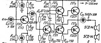
Further improvement resulted in the complete abandonment of this scheme. Many different circuit solutions were tried. Attempts to find the best option led to the solution that I propose. At the input, I used a cascode UA with high linearity, then a phase-inverted cascade with a divided load, which has the highest linearity. At the same time, I connected them directly to reduce phase shifts along the signal path. At the output, however, the familiar ultra-linear output stage remained with minor changes (for the purpose of ease of setup and increased stability), and, as already mentioned, with an improved output trance. In the diagram, I conventionally divided the preliminary stages, a bunch of triodes in which is actually my know-how ;), and the output stage, instead of which you can connect any suitable one. With a properly manufactured and adjusted amplifier, the maximum amplitudes on the control grids of the output lamps should be at least 80V at a load of 47k. And this made it possible to fully pump up the 6P45S. And what’s important is that, for all its advantages, the scheme turned out to be even simpler than the one we had to abandon.
The result is an amplifier with a sound that (with proper measures) can easily qualify for hi-end. The amplifier is absolutely stable, so it can be used both with deep OOS and without it at all - the linearity of all stages ensures low distortion even with an open loop OOC.
From two 6P3S, I managed to get >150 watts, from two 6P45S - >220 ;), and in the version with grid currents (especially for musicians) - 400 watts of peak power! But that diagram is already noticeably different from the one given.
I can’t give detailed parameters of the amplifier now - I haven’t measured it for a long time. For those who need sound and not parameters, I have given enough information for repetition, and if it is really necessary, I can (albeit at great cost) re-measure them. I would probably try it on for a magazine. And here it will do :o)
As for setup, it is simple:
- assemble a standard parameter measurement scheme;
- disable OOS;
- turn on the power and warm up the cathodes;
- resistors R10 and R11 set the quiescent currents of the output. lamps 30...60mA (0.06...0.12V at the cathodes), but always identical;
- without supplying a signal to the input, use the R2 regulator to set the cathode of the bass reflex to 105V;
- apply a signal to the input until the load voltage reaches 15 volts (for a 6-ohm variant);
- resistor R9 sets the minimum of the 2nd harmonic at the output;
- restore OOS (optional).
Point 7 can be skipped if you replace R8 and R9 with one with a resistance of 12k (this may not even affect the quality in any way, especially with OOS).
To power the amplifier, additional voltages were needed: 410V (10mA/channel) and stabilized 68V (b/t). The diagram shows one of the options for obtaining them from the available ones. Here you can do it in different ways. For example, I have a stub source. +220V to power the preamplifier, so I got +68 as a divider.
At one time, the scheme was shrouded in trade secrets. Now please - let anyone who wants to try it. I repeat that the UN-FI combination is universal and can be used to drive various PP output stages (triode, pentode, class A, AB). For each specific case, you may have to recalculate some elements, which is done very easily. This is how I can help those in need.
PS: “Priboy” amplifiers lend themselves well to such modifications – the quality improves noticeably.
Author: Vladimir Vasilyev
You may be interested in:
| Radio tubes used in the article:
|
Comments on articles on the site are temporarily disabled due to a huge amount of spam.
Advertising:
https://events-tent.ru rental of furniture and dishes.
More about tube amplifiers and their practical examples
There will be an article with pictures here. You can show a simplified version of the circuit design of an amplifier using 6P3C lamps. This light bulb is not marked anywhere in the table of contents of the site, but the amplifier is made on it. The 100U-101 broadcast amplifier can be used as a donor for building a 6P3S tube amplifier. From there they take only the output transformer. You can try to use a security force. However, you need to be careful here. Dissipation should first be carefully assessed by measuring the no-load current. If the current is no more than 50 mA, then feel free to use it. If the current is bad, then just sell this hardware to a beginner. The background level in amplifier construction is not yet important to him.
It is better to use ceramic sockets for 6P3S (suitable for GU-50), since the lamp gets very hot. Carbolite can burn and smell disgusting. The remains of the 100U broadcast amplifier can be safely thrown into the trash. The 6P3S lamp is nothing outstanding. Moreover, the cylinder is too small for the declared power dissipation along the anode. The anode terminals are located on top of the cylinder, this is not very convenient. But each cylinder contains two beam tetrodes, similar in characteristics to 6P3S. The halves of the lamp do not differ in symmetry, so it is better to parallelize the tetrodes of one cylinder by placing equalizing resistors on all sides. The output transformer will operate in a lightweight mode since it is designed for parallel operation of three halves in the original 100U circuit. If you provide forced air cooling, you can load more light bulbs. An example of cutting an iron sheet to make a body is shown below.
An example amplifier circuit is shown below. Unlike the 100U amplifier, both halves of the lamp are used in parallel connection.
The scheme is typical, the swing is quite enough. But it’s worth showing a picture of the output transformer circuit. This is a typical transformer from a 100U tube amplifier. This device looks like a square box, often blue in color, with one indicator on the front panel. The point of this amplifier is its size. Purpose: broadcast. Therefore, its output transformer is specific for operation on a long line. And you need to remake the transformer in a simple way, by ordinary re-soldering.
Before use, it must be carefully inspected, unnecessary connections removed, and an audit carried out. Amplifiers 100U-101 are old, often rusty. Be sure to check the windings with a megometer. If there is no obvious defect, then the transformer is then soaked in paraffin. It needs to be thoroughly soaked. Half an hour in a paraffin bath at 80-90 degrees. You can heat it on the stove, in the countryside, so you don’t smell the paraffin stench. I have more advanced drawings for the output transformer circuit, but I won't show them yet. These standard pictures are enough for understanding.
Evgeny Bortnik, Krasnoyarsk, Russia, March 2013
Push-pull almost “triode” ULF on 6P3S and 6P3S-E
(full author's version)
Typical mode of output stage lamps (from the reference book):
Ea = 360 V, Eg2 = 270 V, Eg1 = minus 22.5 V, Raa = 6.6 KOhm,
Ia = 2 x 44 mA, Ig2 = 2 x 2.5 mA, At Uin = 0.
Ia = 2 x 66 mA, Ig2 = 2 x 7.5 mA, At Uin = 45 V amp. P = 26.5 W, Kni = 2%.
No recommendation was found in the datasheet for this lamp for the percentage of screen grid voltage for ultra-linear turn-on. Therefore, by a strong-willed decision, based on the developer’s own experience, the value of 33% was adopted. However, it must be understood that ultra-linear switching significantly reduces the output power of the amplifier relative to the given reference data for “pure” push-pull amplification in class AB mode. This occurs due to the fact that when the lamp is opened, with a positive half-wave of the input voltage, not only the anode (output) voltage decreases, but also the screen grid voltage, which leads to a decrease in the amplitude of the anode current, relative to the value to which the lamp could open when constant voltage of the screen grid. Due to the introduction of ultralinear feedback, the characteristics of the output stage lamp are close to those of triodes. By smoothly changing the percentage of alternating voltage on the screen grid, for example, using a potentiometer, you can establish the optimal ratio between the maximum output power and the “triode” sound. But it is better for each radio amateur to do this individually to his own taste. Of course, the 26.5 watts given in the reference data at an alternating voltage on the screen grid of 33 percent of the anode cannot be obtained, but the amplifier will sound especially gentle.
Carrying out similar calculations as for the previous scheme, we find:
Uaa = 592 V, Ua = 296 V, Ua eff = 210 V.
Based on the above calculations, we also note that we can get an output power of 26.5 W from the TAN transformer only at a 4 Ohm load. We will rely on this for our amplifier. The required transformation ratio for a resistance ratio of 6600 to 4 is 40.6.
Since the voltage across a 4 Ohm load with an output power of 26.5 W should be 10.3 V, we can use taps of filament windings when accurately selecting the required turns ratio. We are satisfied with the following switching options: 5 + 5 = 10 V (with a slight overload of 0.3 V), 5 + 5 + 1.3 = 11.3 V and full switching: 5 + 5 + 1.3 + 1.3 = 12.6 V.
So, we need to select a transformer that has a double set of windings with voltages in two combinations: 110 + 100 and 127 + 83. In a real selected transformer, these voltages may be a little higher, but in no case less! And at the same time, so that there is one more (a pair, of course) winding to power the screen grid with a voltage of 210 / 3 = 70 V.
As mentioned earlier, the power of the selected transformer should be around 100 W. However, it is of interest to use for this circuit slightly more powerful transformers with a rod core and an arrangement of windings on two symmetrical coils. This is a series of transformers from TAN69 to TAN82 with a power of 122 W.
According to the calculated initial data, two transformers satisfy us:
TAN72-127/220-50, – combination of windings 127 + 80 + 24 (anode) and 56 – screen;
TAN73-127/220-50, – combination of windings 127 + 80 + 20 (anode) and 80 – screen;
In this case, the “ultralinear” screen winding for TAN72 will be 24% of the anode winding, and for TAN73 – 35%. The connection circuits for both transformers are the same.
At the same time, in order to maintain the required transformation ratio as accurately as possible, the load must be connected to the output filament windings connected to a voltage of 11.3 V (5 + 1.3 + 5). In this case, the transformation coefficient will be:
for TAN72 coefficient: 2 x (127 + 80 + 24) / 11.3 = 40.9 and at the same time Raa = 6686 Ohm.
for TAN73 coefficient: 2 x (127 + 80 + 20) / 11.3 = 40.2 and at the same time Raa = 6457 Ohm.
The presence of both transformers (and they are very inexpensive) opens up the possibility of experimenting with the magnitude of the alternating voltage on the screen grid.
The beginning of the primary (mains) winding must be included in the anode circuit of the lamp. This pin has the minimum capacitance for the remaining windings. Then, sections of the anode windings are turned on sequentially in increasing order of their terminal numbering. This inclusion of the windings allows you to obtain the maximum bandwidth of the transformer, which, in general, is not intended for use as an output.
This circuit uses a combined bias to the control grids of the output stage lamps. Automatic biasing due to the common current of both lamps provides 40% of the bias voltage, and the remaining 60% is set from a separate rectifier and balancing circuit.
The only difference between the preliminary stage and the previous circuit is that the phase inverter with a split load is powered by a higher anode voltage to ensure good linearity of amplification with a significant swing (double amplitude) of paraphase voltages (two times 45 volts).
The first switching on and adjustment of the amplifier are completely identical to the previous circuit. The rectifiers are assembled according to classic full-wave circuits and do not need any explanation.
The sensitivity of the amplifier at a frequency of 1 KHz at maximum output power is 0.775 volts effective value. And the bandwidth with an average output power of 8.5 W from 24 Hz to 24 KHz over the blockages is minus 3 dB.
The amplifier assembled by the author with the TAN73 transformer showed excellent sound with very rich low frequencies, a hard “middle” and very gentle and transparent high frequencies. In this circuit, not only 6P3S and 6P3S-E lamps were tested, but also 6F6S, EL34 and 6550.
The most “delicious” and pleasant sound was provided by 6F6S output tubes, however, with a load of 8 ohms and the output windings being fully turned on.
Here is a brief emotional description of the sound of an amplifier with different tubes:
6P3S-E
– The sound is elastic, as if slightly compressed, powerful lows, and very clear highs. But this sound is oppressive and you won’t listen to it for a long time. It sounds just like guitar amps! This is an analogue of the American 5881, which is exactly what is used in these combos. She has an electric guitar sound. It is still not quite 6L6, which is almost an exact analogue of our 6P3S.
6P3S
– Transparent natural sound with very good separation and audibility of both soft and powerful sounds. All overtones and different instruments are clearly audible.
6F6S
- Very interesting sound. You can listen all day long – it doesn’t tire you. Everything is very transparent, gentle and musical!
6550
– Strong powerful sound. Solid, one might say. The lows sound, as my brother puts it, “your fur coat is wrapping up”!
EL34
– Deep powerful lows, very gentle highs and hard mids. The voice sounds very harsh. However, the piano sounds tenderly.
6P6S
- no way. It's dead and tasteless. It is not suitable for this amplifier. A bit weak.
And I also saw the difference in sound that the pre-tube makes.
6N8S
– ours, classical, gives a slightly smeared soft sound.
6Н8С-6SN7
RFT 1954. There were some with a double name, they give a very hard and clear sound - as if it was written according to the rules! And the tops become like steel!
6N9S
– when combined with the EL34, it gives a rather interesting sound with emphasis on the high frequencies. The brushes are very emphasized. However, the lows sound relatively colorless. And in the kit with 6P3S there was no sound at all... so, something incomprehensible and “nothing”.
Lamps 6550
and
EL34
are too powerful for this amplifier. You can install them and they work fine, but they require higher voltages and more powerful transformers - two to three times! And the food is different. On the 6550 you need, as a rule, 600 volts for the anodes and 300 volts on the screen grids, and on the EL34 - 800 and 400, respectively. Then they will start singing!!! You need to wind custom transformers for them! Or buy from serious audiophile companies. These are already very serious lamps.
However, this amplifier works optimally on conventional 6P3S tubes with a 6N8S pre-stage. Which is what I recommend!
Since in circuit 2 the screen grids of the output lamps are powered by 1.38 times lower voltage than the anodes, this is equivalent if not 24% and 35% of the alternating anode voltage were applied to the screen grids, but 33% and 48%, respectively.
The author made such an amplifier using a TAN73 transformer, and with such a high value of alternating voltage on the screen grid, 48%, the output power of the amplifier was 12 watts. At the same time, its sound was very reminiscent of triode amplifiers.
In general, the toy is what you need!!! And this is on ordinary cheap TANs!
Lamp saucepans!
Dear Sergey!
You described your amplifiers on TAN-ahs so professionally and infectiously that in my old age I decided to try to assemble circuit No. 2 on 6P3S-E. I assembled two monoblocks. I am sending you their photographs. This is my second tube design (the first was an oscilloscope built after school in 1975).
The idea to use a 4-liter saucepan as a body came after visiting a hardware store. The case, if made taking into account both aesthetics and functionality, is an expensive and labor-intensive part, but here is the finished product - nickel-plated, with handles and not expensive (350 rubles). By chance, the height of the pan coincided with the height of the transformer. I cut out the lid from 5 mm using a jigsaw. duralumin and it became the main load-bearing element. The pan has not undergone any changes. Can be used for its intended purpose at any time. There was a question of ventilation, but after half an hour of operation nothing got particularly hot. The hottest element turned out to be the resistor in the 6p3s cathodes, but I increased its power by 2 times. In the end, you can drill holes (like in a colander), but this has not been necessary yet.
The lamps are protected from damage by beautiful grilles - stands either for toothbrushes or for something else, bought at the same hardware store.
That's all, actually.
Thank you very much, Sergey, for such feedback about my design. I’ll show my wife, maybe it won’t be so loud that the apartment stinks of rosin. I dare to invite you over for a “glass of tea.”
Best regards, Boris Trunov
Pots on the kitchen windowsill. Two terminals and pre-amplifier:
Final amplifier layout:
Installation of the final amplifier. Side view:
Installation of the final amplifier. View from above:
Author: Sergey Komarov
,UA3ALW
Radio magazine No. 5, 2005
From the site radiostation.ru