The circuit design of a tube vinyl corrector is presented on the website radiochipi.ru Despite the low gain, the 6N8C lamp has a lower (compared to other available octal family lamps) internal resistance value. By including it in the SRPP, you can achieve a reduction in the output resistance to 2...2.5 kOhm, which is quite acceptable for the output stage of a vinyl corrector (developed by A. Mayakov), the circuit of which is shown in Fig. 2.22
Pay attention to the method of supplying mixing using an LED (or a zener diode in the first stage) and a zener diode (but in the second stage).
This is the so-called quasi-fixed mixing , characterized by ease of implementation and the highest stability, unattainable with other displacement implementation options.
The “fly in the ointment” in this case is the additional nonlinearity introduced by semiconductors and the need to select diodes due to the spread of their parameters. Of course, quasi-fixed bias can only be used for lamps operating at low (several milliamperes) anode currents. Under no circumstances should you remove the shunt capacitors in the cathode circuits of the lamps, which are necessary to suppress the noise of the zener diode and LED. Remember that high-class lamp designs (and Manakova’s corrector is one of those) do not have “extra” parts! About the purpose of switch S1.
A number of developers (for example, Sakuma) use correction circuits that differ from the standard ones, selecting the values either “by ear” (within reasonable limits) or for a specific musical genre. The developer of the vinyl corrector was guided by similar considerations, introducing an additional switch element that allows the listener to select the appropriate mode.
The tube corrector has excellent sound, the circuit is easy to manufacture, and is highly recommended for radio amateurs.
Attention! When repeating the circuit, it is necessary to apply a positive potential of about 100 V to the heater of the VL2 (6H8C) lamp.
↑ It all started with headphones
“Shouldn’t you sing me a song?!” No, not this time. This time I will tell you how I tried to make sure that those who sing songs for us could fully convey these songs to our ears.
It all started when I tried to listen to Sennheiser HD600 headphones in one of the online electronics stores.
The impression was simply knocking me down. I don’t know what it was all connected to, but the sound was great when compared to other headphones displayed on the same stand. But the high price did not allow me to buy them right away. And I decided to buy them in Moscow, through an online store. My beloved brother lives in Moscow, and we agreed that he would buy them and have them delivered to his work (which was a third cheaper than the price in a chain store), and I would come and pick them up. Everything worked out, but we were ambushed - my brother liked their sound so much that he also wanted to get the same ones for himself. It was decided not to take the same ones, and the second one we bought was the Beyerdynamic DT 770 PRO. As a result of the audition, the Senkhs went to my brother, and the Bayers went to me. At the same time, we bought a simple DAC for my brother. So, having 2 pairs of high-impedance, high-end headphones, I started thinking about a tube headamp. Or rather, over two. I was looking towards Laconic Lab products, but can’t I really assemble something similar myself? Moreover, there is experience in building UPS for tube amplifiers.
Radio tube 6N8S
Radio lamp 6N8S A directory of the content of precious metals in radio components based on reference data from various organizations involved in the processing of scrap radio components, device passports, forms and other open sources. It is worth noting that the actual content may differ by 20-30% downwards.
Radio tubes can contain gold, silver, platinum and PGMs (Platinum group metals, Platinum group, Platinum metals, Platinoids, PGE)
Content
Content of precious metals in the radio tube: 6Н8С
Gold: 0 Silver: 0.0041 Platinum: 0 MPG: 0 According to: Handbook of Precious Metals ORDER No. 70
An electron tube or radio tube is an electric vacuum device (more precisely, a vacuum electronic device) that works by controlling the intensity of the flow of electrons moving in a vacuum or rarefied gas between the electrodes.
Main types of electronic vacuum tubes:
Diodes (easily made for high voltages, see kenotron) Triodes Tetrodes Pentodes and Beam tetrodes Beam pentodes (as a variation of this type) Hexodes Heptodes (pentagrids, five-grid) Octodes Nonodes Combination lamps (actually include 2 or more lamps in one cylinder) Discharge lamps
Designation system for lamps produced in the USSR
The first part of the marking is a number indicating the rounded value of the filament voltage (for receiving and amplifier lamps): 06 - 625 mV 1 - 800 mV, 1 V, 1.2 V, 1.4 V, 1.5 V 2 - 2 V, 2.2 V, 2.4 V 3 — 3.15 V 4 — 4 V, 4.2 V, 4.4 V 5 — 5 V 6 — 6 V, 6.3 V 7 — 7 V 9 — 9 V 10 — 10 V 12 — 12 V, 12.6 V 13 — 13 V 17 — 17 V 18 — 18 V 20 — 20 V 25 — 25.2 V 30 — 30 V
Generator tubes, barretters and zener diodes have a letter index indicating the type of lamp: GI - Pulse generator tube GM - Modulating tube GMI - Pulse modulation tube G - Generator tube (for older lamps) GK - Generator HF lamp (for frequencies up to 30 MHz ) GU - (For example, GU-50 Generator VHF lamp (for frequencies up to 300 MHz) GS - Generator microwave lamp (for frequencies above 300 MHz) GP - Regulating lamp GPI - Regulating pulse lamp SG - Gas-filled voltage stabilizer (zener diode) ST - Gas-filled current stabilizer (baretter)
The second part of the marking is a letter (or two letters) of the Russian alphabet, indicating the type of electrode system of the lamp (for receiving and amplifier lamps): A - Frequency-conversion lamps (hexode, heptode) B - Diode-pentode, double diode-pentode (combined lamp) C — Lamp with secondary emission G — Diode-triode, double diode-triode, triple diode-triode (combined lamp) D — Single diode (except for rectifier kenotron) E — Electron-light indicator G — High-frequency pentode with a short characteristic I — Triode- heptode or triode-hexode (combined lamp) K - High-frequency pentode with an extended characteristic ("varimu") L - Beam lamp (except for the beam tetrode) M - Double pentode (only one lamp of this type was produced - 12M1M) N - Double triode P - Output pentode or beam tetrode P - Double tetrode, double beam tetrode or double pentode C - Triode T - Thyratron with a cold cathode (only one thyratron was produced with the designation adopted for receiving and amplifying tubes - 1T1A) F - Triode-pentode (combined tube ), exception - pentode of the old production 6F6S X - Double diode (except for kenotrons) C - Rectifier diode (kenotron) of any type E - Tetrode SR - Double pentode-triode
For cathode ray devices: LI - Transmitting tube LC - Kinescope with electromagnetic beam deflection LM - Oscillographic tube with electromagnetic beam deflection LN - Storage tube LNS - Character-printing storage tube LO - Oscilloscope tube or kinescope with electrostatic beam deflection LP - Cathode-ray switch LS - Character-printing tube LF - Functional tube
The third part of the marking. For generator and receiving-amplifier tubes, picture tubes and oscilloscope tubes there is a number indicating the development number. For zener diodes and barretters it is the same as the 4th element for receiving and amplifying tubes.
The fourth part of the marking. It is absent for zener diodes and barretters. For picture tubes and oscilloscope tubes, it can indicate the type of phosphor used for the screen. For receiving and amplifying lamps - a letter indicating the design of the lamp: A - Subminiature glass cylinder with a diameter of 5-8 mm with flexible wire leads B - Subminiature glass cylinder with a diameter of 8-10.2 mm with flexible wire leads D - Miniature glass cylinder with a diameter of more than 10.2 mm with flexible wire leads D - Ceramic cylinder with disk leads ("beacon" lamps) F - Acorn-type lamp - a miniature glass cylinder with rigid radial leads. K - Ceramic cylinder with pin leads. L - Lamp with an octal base equipped with a lock, which prevents the lamp from falling out of the panel when shaking (“octal”). The cylinder is glass, covered on the outside with an aluminum casing. M - Small-sized glass cylinder with an octal base of reduced height (“malgab”). The letter is retained only for some lamps of older releases (2K2M, 2Zh2M, 2P9M, 30Ts1M, etc.). N - Nuvistor (miniature lamp in a metal-ceramic cylinder). P - Miniature (“finger”) lamp — a glass cylinder with a diameter of up to 22 mm with seven (“heptal”) or nine (“noval”) rigid leads soldered directly into the bottom. C - Large glass cylinder with a diameter of more than 22.5 mm or a metal-ceramic cylinder, including one with an octal base. P - Subminiature glass cylinder with a diameter of less than 5 mm with flexible wire leads. The only lamp produced in this design was 1Zh25R) No letter - Metal (usually steel) cylinder with an octal base
For generator lamps - a letter indicating the type of cooling: A - Forced liquid, water or air-water B - Forced air K - Contact P - Evaporative No letter - Natural air
The fifth part of the marking characterizes the special properties of the lamps. Optional, always placed with a hyphen, applicable only to receiving and amplifying lamps. B - Lamp of increased mechanical strength and reliability E - Lamp of increased durability (5000 hours or more) D - Lamp of particularly high durability (10,000 hours or more) I - Lamp designed to operate in pulsed mode K - Lamp of increased mechanical strength and reliability with increased vibration resistance P - Lamp of increased mechanical strength and reliability, with increased radiation resistance (better than B; however, to replace a group B lamp, both P and B must be present in the designation)
Share link:
Liked this:
Like
Similar
↑ Zero cycle
The zero option was a 6n8s+6n13s amplifier with a traditional power supply circuit design based on the famous TL494.
The microcircuit is old, clear and successful. The amplifier was successfully manufactured, installed in a converted case from a computer power supply unit and taken to my brother. He lived happily, but not for long - due to icing of the wires last winter, not 220 Volts appeared in the outlet, but more. The result is sad - the amplifier came to me for repairs. Yes, the TL494 is good - stabilization, protection, not expensive. But the barrel contained half honey and tar - it cannot work with mosfets (it can, but it requires an external driver). Therefore, the radiator for the half-bridge should not be small, and a matching transformer is needed, a large (relatively) piping...
↑ Proper nutrition is the key to health!
I thought.
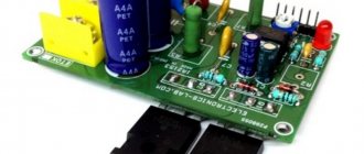
By this time, I had experience in designing a non-stabilized power supply based on the IR2153 (bipolar power supply for the TDA7294 amplifier). “IRKa” (IR2153) is famous for its simplicity, unpretentiousness, simple power supply and built-in mosfets driver. But even here the barrel is not full of sweets - no protection, no stabilization. Which is confirmed by a bunch of burnt microcircuits for everyone who dealt with them. As a matter of fact, it is precisely because of this that this microcircuit has earned itself a bad reputation. I don’t intend to debunk this opinion, I just think differently, that’s all. But actually, why do we need stabilization? Let's remember how our fathers and grandfathers made tube circuits. Was the heat there stabilized? No, and everything worked. And they still make amplifiers on TANs, using a 6.3 Volt variable for incandescence. Is it always 6.3? Not always, but it depends only on the voltage in the network and the load on the filament. So if you wind the power transformer correctly and get 6.3 at the output of the rectifier at a nominal 220 Volt network - that’s it, the problem is solved. Well, it will wander a little, so the lamps were created with this in mind.
Current protection is simply implemented - a current transformer, a pair of transistors and the same number of resistors and capacitors. The previous 3 paragraphs included several months of reflection, extensive correspondence with AlexD
(Lesha, you are mighty, my deepest bow!), a bunch of burnt IR2153 and IRF740 and several test boards.
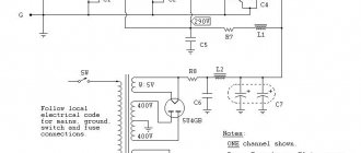
Here's an idea diagram:
Fragment excluded. The full version is available to patrons and full members of the community.
I’ll make a reservation right away that although it works for me on one of the amplifiers, I don’t recommend repeating it in this form: there is no protection here. The slightest shortness in the load and you can immediately safely change the driver and transistors.
I will specifically focus on anode voltage rectifier diodes. Under no circumstances use conventional rectifier diodes! Only ultrafasts. This is an axiom for this scheme. Neglect cost me a set of mosfets. The reason is simple - a large reverse current during recovery when the diode is closed. With 50Hz rectification this doesn't really matter. But we rectify 60-70 kHz! Not only does the reverse current overheat the snubber of the power trance primary, but the diodes themselves get quite hot from it. And after the breakdown of one of them, the entire half-bridge is safely carried away...
The rest of the scheme does not require comments; everything has been discussed many times on many resources. I can only make a couple of comments from myself. Do not skimp on capacitor C26, this is the power supply for the upper arm of the driver. In the datasheet it is smaller, but I always set it to about 10 uF. D4 is not necessarily ultrafast. P1R3C8 determine the frequency of square wave generation, which is equal to 1 / (1.4 * (R3+P1+75) * C8). However, there are several online calculators for this chip on the network. So, the frequency for this number of turns of the power transformer should be 60-70 kHz.
I don’t set a trimmer, I just count at approximately 65 kHz, that’s all. The reason is there is not enough space on the board. A power transformer from a computer power supply is wound like this: 19 turns with a 0.6 mm wire - the first half of the primary, then an oblique of 2 wires in 0.6 mm filament 2 by 2, then about 40-45 turns with a thin wire (0.12 mm) anode, then the remaining half of the primary 19 turns. The anode is selected experimentally; it is better to start with a small (30) number of turns.
Diagram of using a 6N8S lamp as a low-frequency voltage amplifier
| When designing a cascade of a low-frequency voltage amplifier using resistances (see figure), it must be remembered that when using a small anode load, the cascade gain decreases and the frequency response expands. With a relatively high anode resistance, the gain of the cascade increases, and the frequency response of the cascade narrows. The capacitor that blocks the resistance in the cathode circuit is usually taken electrostatic, with a capacity of 10-50 μF. The values of resistance and transition capacitor for the circuit shown in the figure are given in the table. |
Details of the low-frequency amplifier stage on the 6N8S lamp
_____________________________________________________________________ | Circuit resistance | | | | |__________________________________________| Transitional | Output |Coefficient- | | anode | mesh subsequent | cathode |capacitor,|voltage,| patient | |Ra, MΩ| cascade Rc, MOhm |Rk, kOhm| µF | In |gain| |_______|_________________|________|____________|___________|________| | Power supply voltage 180V | |_______________________________________________________________________________| | 0.05 | 0.05 | 1.2 | 0.05 | 24 | 13 | | 0.05 | 0.1 | 1.5 | 0.02 | 30 | 13 | | 0.05 | 0.25 | 1.8 | 0.01 | 30 | 13 | | 0.1 | 0.1 | 2.4 | 0.05 | 26 | 14 | | 0.1 | 0.25 | 2.8 | 0.01 | 34 | 14 | | 0.1 | 0.5 | 3.2 | 0.005 | 38 | 14 | | 0.25 | 0.25 | 5.5 | 0.01 | 28 | 14 | | 0.25 | 0.5 | 7.0 | 0.007 | 36 | 14 | | 0.25 | 1.0 | 8.0 | 0.004 | 40 | 14 | |_______|_________________|________|____________|___________|________| | Power supply voltage 300 V | |_______________________________________________________________________________| | 0.05 | 0.05 | 1.0 | 0.5 | 41 | 14 | | 0.05 | 0.1 | 1.2 | 0.03 | 51 | 14 | | 0.05 | 0.25 | 1.5 | 0.01 | 60 | 14 | | 0.1 | 0.1 | 2.0 | 0.03 | 43 | 14 | | 0.1 | 0.25 | 2.4 | 0.01 | 56 | 14 | | 0.1 | 0.5 | 2.7 | 0.006 | 64 | 14 | | 0.25 | 0.25 | 4.5 | 0.01 | 46 | 14 | | 0.25 | 0.5 | 5.7 | 0.007 | 57 | 14 | | 0.25 | 1.0 | 7.0 | 0.004 | 64 | 14 | |_______|_________________|________|____________|___________|________|
↑ Well, so that the amplifier eats, but does not overeat
And now the complete circuit, with a current transformer:
Fragment excluded.
The full version is available to patrons and full members of the community. Regarding current protection:
you will have to select the rating of R9 and R10. It all depends on the material of the ring and wire. I had to install R10 4.7 kOhm and remove R9 altogether. It took me a long time to figure this out, because in all such circuits the load resistor has a nominal value of 10-15 Ohms, and in general, the principles of the current transformer say that it should be loaded with a “low-ohm load”.
But if you have a wire as thin as mine, then 10 Ohms will simply reduce the secondary voltage, and that’s all. The ring itself (current transformer): on ferrite no worse than 1500-2000, the secondary 80-100 turns of any wire that will fit is wound into 2 wires, then the end of the first is connected to the beginning of the second. The primary is simply a thick (0.8 mm is enough) U-shaped piece of wire passed into the ring.
For tuning, I would not recommend shorting the filament to ground. Load it in series with powerful resistors of 300, 100, 30, 10 Ohms and see what voltage there is across the load resistor. Keep in mind - the load in the heat will not be weak! In operating mode it is about 3 A, but cold filaments have much lower resistance. So 0.2-0.5 Ohm is approximately what awaits you when starting in heat...
Now it's time to think about the amplifiers themselves!
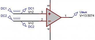
Basic electrical data at low anode voltage (for each triode)
| Anode voltage, V | 26 |
| Grid bias voltage, V | -0.5 |
| Characteristic slope, mA/V | 1.5 |
| Internal resistance, kOhm | 16 |
| Gain | 24 |
Characteristics of the dependence of anode current on anode voltage
Characteristics of the dependence of the anode current and grid current on the anode voltage
Current in the anode circuit; current in the grid circuit.
Dynamic characteristics of the dependence of the anode current on the grid voltage at a power source voltage of 250 V
Characteristics of the main parameters of the 6N8S lamp at an anode voltage of 250 V
↑ Amplifier No. 1: four greyhound tetrodes 6E5P
Fragment excluded. The full version is available to patrons and full members of the community.
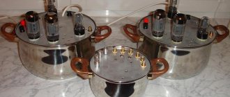
Wonderful lamps. Connection circuit: SRPP, parallel controlled two-tube amplifier. All information on the scheme is on Google. The setting comes down to one thing - the output before the coupling capacitors should be half the anode voltage. With new identical lamps and compliance with the circuit ratings, this is done automatically.
Lamps 6E5P and 6E5P-I
Lamps 6E5P and 6E5P-I differ in size and passport. Pmax of the anode is 3 Watts for 6E5P-I versus 8 Watts for 6E5P. However, this is not critical for the earpiece, and no differences were found in sound. In the end I installed 6E5P-I, because... they turned out to be available in sufficient quantities.
Looks decent and cool:
Scheme of using a 6N8S lamp as a bass reflex
| The figure shows a diagram of a bass-reflex self-balancing cascade. The inclusion of grid resistances, as shown in the diagram, forms a strong negative feedback, under the influence of which the excitation voltage on both lamps of the push-pull cascade is automatically set to the same. The balancing of the circuit is not disturbed by significant changes in resistance values, lamp parameters and supply voltages. The circuit is recommended only for exciting terminal lamps operating in a mode without grid currents, because the output impedance of the phase inverter stage is large. |
↑ Amplifier No. 2: almost vintage 6N8S and 6N13S tubes with an octal base
Fragment excluded. The full version is available to patrons and full members of the community.
A minute for 6Н13С.
I got it by accident. I wandered around the radio market in search of hardware for the output transformers of the next amplifier. And what caught my eye were two beautiful lamps in pear-shaped cylinders, and octal... Yes, new! Still not knowing what it was, I couldn’t resist and bought it (the price was reasonable). Arriving home, I turned to the great guru AlexD
, who enlightened me on what these double triodes are. Going to the market for drivers for them (6H8S, because I wanted everything in octal) was a matter of 15 minutes. And a little more lyricism - oh, in vain they criticize them on the forums (I’m talking about 6N13S), oh in vain... Apparently not everyone knows how to cook them. And they even look delicious:
To the circuit:
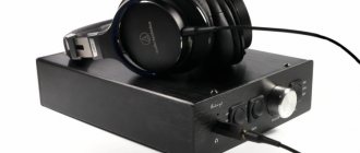
a simple cathode follower. The power dissipated by the R7 is high. Therefore, I have 4 pieces of 2-watt 18 kOhm resistors, connected in parallel. And then they heat up noticeably.
As a result, don’t get carried away with the anode; at 150 Volts it already sings well. Moreover, I conducted an experiment, they sound good already at 60 Volts of the anode, but in general the sound comes from 30-40 Volts without distortion. The experiment came out naturally - my delay time for the anode supply on the electronic choke was as much as 3-4 minutes. I love, you know, the smoothness in the anode. So, on a cold lamp, I turned the voltmeter to the anode and turned it on when the signal was already present at the input.
At 20 Volts the sound was distorted, and above that you already know. The circuit does not require any configuration. Before sending a signal and connecting headphones, check that there is no constant voltage at the output, otherwise you never know what if you get a defective capacitor? Headphones are expensive, these are not fixed-price headphones for iPhone...
We talk about guitars
Below is data on imported radio tubes and their possible analogues, indicating the filament voltage ( Uн ), filament current ( Iн ) of the radio tube.
| + close analogue, direct replacement possible | |||||||||
| ~ analogue in all respects except heat | |||||||||
| # close analogue; differences in some modes and pinouts. | |||||||||
| […] a very approximate analogue | |||||||||
| * high reliability lamp |
KENOTRONS
| Lamp | Un | In | Analogue |
| 5Z4 | 5 | 2 | = 5Ц4С |
| 5Y3 | 5 | 2 | # 5TS4M |
| 5W4 | 5 | 1.5 | # 5TS4M |
| Analogues: | |||
| 5Z4 = GZ30 = 5CG4 | |||
| 5Y3 = U50 = 6087 = 6106* | |||
| Lamp | Un | In | Analogue |
| 5U4G | 5 | 3 | = 5Ц3С |
| GZ32 | 5 | 2 | # 5TS3S |
| GZ34 | 5 | 1,9 | # 5TS3S |
| Analogues: | |||
| 5U4G = U52 = 5Z3 = 5AS4 = 5Z10 = 5931* | |||
| GZ32 = 5AQ4 = 5V4G | |||
| GZ34 = 5AR4 | |||
| Lamp | Un | In | Analogue |
| EZ82 | 6.3 | 0.6 | # 6Ц4П |
| EZ90 | 6.3 | 0.6 | # 6Ц4П |
| HZ90 | 12.6 | 0.3 | # 6Ц4П |
| 6X5GT | 6.3 | 0.6 | = 6Ц5С |
| 12X5GT | 12.6 | 0.3 | ~ 6Ts5S |
| Analogues: | |||
| EZ90 = EZ900 = U78 = 6Z31 = 6063 =6X4W* = 6202* | |||
| HZ90 = 12X4 | |||
| 6X5GT=EZ35=U70 | |||
TRIODES
| Lamp | Analogue |
| 7586 | = 6С51Н |
| 7895 | = 6С52Н |
| EC1010 | = 6С53Н |
| 6B4G | = 6C4C |
| 6BK4 | = 6C20C |
| 811A | = G-811 |
| Lamp | Analogue |
| 6J5(GT) | = 6C2C |
| 6C5(GT) | = 6C5C |
| 6F5(GT) | = 6Ф5С |
| 9002 | = 6C1P |
| Analogues: | |
| 6F5 = H63 | |
| 6J5GT = L63 | |
| Lamp | Un | In | Analogue |
| EC98 | 6.3 | 0.4 | = 6C2P |
| EC86 | 6.3 | 0.2 | # 6С3П # 6С4П |
| EC806* | 6.3 | 0.165 | # 6С3П # 6С4П |
| PC86 | 3.8 | 0.3 | # 6С3П # 6С4П |
| Analogues: | |||
| EC98 = 6J4(WA*) = 6C31 | |||
| EC806S = E86C* | |||
| PC86 = E7075 = 4CM4 | |||
DUAL TRIODES
| Lamp | Analogue |
| 2C51 | = 6Н3П |
| Analogues: | |
| 2C51 = 6CC42 = 5670 = 6385 = 6854 |
| Lamp | Un | In | Analogue |
| 12AY7 | 6.3 | 0.3 | ~ 6N4P |
| 36689 | 0.15 | ||
| Analogues: | |||
| 12AY7 = 6072(A) | |||
| Lamp | Analogue |
| 6AS7G | = 6Н13С + 6Н5С |
| Analogues: | |
| 6AS7G = ECC230 = 6080 = 6520 | |
| Lamp | Un | In | Analogue |
| 6SC7 | 6.3 | 0.3 | = 6Н10С |
| 12SC7 | 12.6 | 0.15 | = 12Н10С |
| 6SL7 | 6.3 | 0.3 | = 6Н9С |
| 12SL7 | 12.6 | 0.15 | ~ 6Н9С |
| Analogues: | |||
| 6SL7 ~ ECC35 (Iн=0.4а) =6SU7GT(W*) = 6113 = 6188* | |||
| Lamp | Un | In | Analogue |
| 12AH7 | 12.6 | 0.15 | = 12Н11С |
| 6AH7 | 6.3 | 0.3 | ~ 12Н11С |
| Lamp | Analogue |
| ECC86 | = 6Н27П |
| Analogues: | |
| ECC86 = 6GM8 | |
| Lamp | Un | In | Analogue |
| E88CC* | 6.3 | 0.3 | = 6Н23П |
| ECC88 | 6.3 | 0.365 | ~ 6N23P |
| PCC88 | 7.0 | 0.3 | ~ 6N23P |
| UCC88 | 21.0 | 0.1 | ~ 6N23P |
| E188CC* | 6.3 | 0.335 | ~ 6N23P |
| Analogues: | |||
| E88CC = E7106* = ECC868* = 6922* | |||
| ECC88=E7144=6DJ8 | |||
| PCC88=E7022=7DJ8 | |||
| UCC88 = 21DJ8 | |||
| E188CC = 6922(WA*) = 7308* | |||
| Lamp | Un | In | Analogue |
| ECC89 | 6.3 | 0.365 | ~ 6N24P |
| PCC89 | 7.2 | 0.3 | ~ 6N24P |
| XCC89 | 4.5 | 0.6 | ~ 6N24P |
| YCC89 | 5.2 | 0.45 | ~ 6N24P |
| ECC189 | 6.3 | 0.365 | # 6Н24П |
| PCC189 | 7.2 | 0.3 | # 6Н24П |
| UCC189 | 21 | 0.1 | # 6Н24П |
| XCC189 | 4.5 | 0.6 | # 6Н24П |
| YCC189 | 5.2 | 0.45 | # 6Н24П |
| Analogues: | |||
| ECC89 = 6FC7 | |||
| ECC189 = 6ES8 | |||
| Lamp | Un | In | Analogue |
| 6CC41 | 6.3 | 0.3 | = 6Н2П |
| 6AX7 | 3.15 | 0.6 | # 6Н2П |
| 36591 | 0.3 | ||
| 12AX7 | 6.3 | 0.3 | # 6Н2П |
| 36689 | 0.15 | ||
| 12AD7 | 6.3 | 0.3 | # 6Н2П |
| 36689 | 0.15 | ||
| 12BZ7 | 6.3 | 0.3 | # 6Н2П |
| 36689 | 0.15 | ||
| Analogues: | |||
| 6CC41 = E7018 | |||
| 12AX7 = B339 = ECC803* = E83CC* = ECC83 = E7017 | |||
| = 12DF7 = 12DT7 = 5721* = 6057 = 6681 = 7025 = 7729 | |||
| Lamp | Un | In | Analogue |
| 1G6 | 1.4 | 0.1 | ~ 1Н3С |
| 6N7 | 6.3 | 0.8 | = 6Н7С |
| 6SN7 | 6.3 | 0.6 | = 6Н8С |
| 8SN7 | 8.4 | 0.45 | ~ 6Н8С |
| 12SN7 | 12.6 | 0.3 | ~ 6Н8С |
| 25SN7 | 25 | 0.15 | ~ 6Н8С |
| 6CG7 | 6.3 | 0.6 | # 6Н8С |
| 8CG7 | 8.4 | 0.45 | [6Н1П] |
| Analogues: | |||
| 6SN7 = 6SN7-GT = B65 = ECC32 = 6CC10 = 5692* = 6180 | |||
| 12SN7 = B36 | |||
| Lamp | Un | In | Analogue |
| ECC84 | 6.3 | 0.34 | = 6Н14П |
| PCC84 | 7 | 0.3 | ~ 6N14P |
| UCC84 | 21 | 0.1 | ~ 6N14P |
| Analogues: | |||
| ECC84 = E7019 = 6CW7 | |||
| Lamp | Un | In | Analogue |
| 6J6 | 6.3 | 0.45 | = 6Н15П |
| 5J6 | 4.7 | 0.6 | ~ 6N15P |
| 9J6 | 9.5 | 0.3 | ~ 6N15P |
| 19J6 | 18.9 | 0.15 | ~ 6N15P |
| Analogues: | |||
| 6J6 = ECC91 = 6CC31 =6030* = 6099* = 6101* = 6535 = 6927* | |||
OUTPUT PENTODES
| Lamp | Analogue |
| 807 | = G-807 |
| 6AG7 | = 6P9 |
| 6GB5A | = 6P20S |
| Lamp | Un | In | Analogue |
| 6F6 | 6.3 | 0.7 | = 6Ф6С |
| 6V6 | 6.3 | 0.45 | = 6P6S |
| 5V6 | 4.7 | 0.6 | ~ 6P6S |
| 12V6 | 12.6 | 0.225 | ~ 6P6S |
| 5992* | 6.3 | 0.6 | ~ 6P6S |
| Analogues: | |||
| 6F6 = N63 | |||
| 6V6 = 6AY5 = 5871 = 7184 = 7408* | |||
| Lamp | Un | In | Analogue |
| 6L6 | 6.3 | 0.9 | = 6P3S |
| 6L50 | 6.3 | 1.0 | # 6P7S [6P3S] |
| 6BG6 | 6.3 | 0.9 | = 6P7S |
| 19BG6 | 18.9 | 0.3 | ~ 6P7S |
| 25BG6 | 25 | 0.3 | ~ 6P7S |
| Analogues: | |||
| 6L6 = EL39 = 6CN5 = 1622 = 5881 = 5932* = 7581 | |||
| Lamp | Un | In | Analogue |
| EL34 | 6.3 | 1.5 | = 6P27S |
| EL37 | 6.3 | 1.4 | # 6P27S |
| Analogues: | |||
| EL34=E7032=6CA7=E34L#KT-77 | |||
| EL37 = N66 | |||
| Lamp | Un | In | Analogue |
| EL500 | 6.3 | 1.38 | = 6P36S |
| PL500 | 27 | 0.3 | ~ 6P36S |
| XL500 | 14 | 0.6 | ~ 6P36S |
| Analogues: | |||
| EL500 = 6GB5 | |||
| PL500 = 28GB5 | |||
| XL500 = 14GB5 | |||
| Lamp | Un | In | Analogue |
| EL36 | 6.3 | 1.25 | = 6P31S |
| PL36 | 25 | 0.3 | ~ 6P31S |
| XL36 | 13 | 0.6 | ~ 6P31S |
| Analogues: | |||
| EL36 = 6CM5 | |||
| PL36 = E7040 = 25E5 | |||
| XL36 = 13CM5 | |||
| Lamp | Un | In | Analogue |
| EL82 | 6.3 | 0.8 | = 6P18P |
| PL82 | 16.5 | 0.3 | ~ 6P18P |
| Analogues: | |||
| EL82 = E7039 = N329 = 6DY5 | |||
| PL82 = E7042 = 16A5 = 16L40 | |||
| Lamp | Un | In | Analogue |
| EL84 | 6.3 | 0.76 | = 6P14P |
| XL84 | 8 | 0.6 | ~ 6P14P |
| YL84 | 10 | 0.45 | ~ 6P14P |
| Analogues: | |||
| EL84 = E84L* = E7035 = N709 = 6BQ5 = 6L40 = 7189 | |||
| XL84 = 8BQ5 | |||
Zener Diodes
| Lamp | Analogue |
| 0A2 | = SG1P |
| 0A3 | = SG2S |
| 0B2 | = SG2P |
| 0C2 | + SG16P |
| 0C3 | = SG3S |
| 0D3 | = SG4S |
More about +CubozoaRu
Development and production of unique, programmable power supplies for guitar effects pedals.
↑ Design
Everything is made on printed circuit boards of the same size and assembled in sandwich-shaped racks 50 mm long: the power supply on the bottom, the amplifier board on top.
I made it specifically according to a modular principle so that power supplies could be changed from one device to another. Power supply with 3 wires from bottom to top through terminals. Front input and volume control, rear output. Oh, I’ve heard enough from datagor Alexey ( AlexD
) about the placement of inputs and outputs... I agree, it should be the other way around. But I don’t run traces with a signal back and forth across the printed circuit board above the pulse generator. I will connect it to the connectors on the case (haha, if there are cases) with a good shielded wire.
The details are generally not critical, other than what has already been mentioned. Radiators from computer power supplies, 2 out of 4 had to be cut not only in length, but also in height. They don’t get too hot, the IR thermometer shows a maximum of 60 degrees. The cathode follower ballast gets hotter, 110-120 degrees, be careful. The power supply has a fairly large power reserve; it can easily power a small Pokemon-type tube amplifier.
When increasing power take-off, it is recommended to organize self-powering of the IR2153 with a separate additional winding, Schottky assembly, inductor and capacitor. Such solutions are available on the Internet at every step.
↑ Aim! Fire!
“And why did you start all this?” - the patient reader who has read this sentence will ask. There was an idea to organize a “Battle of the Ears”, to assemble another system according to the circuit of a cascode repeater on 6N23P+2*6N24P (circuit of one of Lakonikov), as well as some kind of semiconductor one. And arrange a blind audition on test discs. But, to be honest, I’m tired of it. Therefore, I took advantage of my wife’s ear for music, the opinions of my son and friend, and I didn’t forget myself. It was tested something like this:
The opinion is unanimous - I like the triode better.
↑ Lancet on Crystal
The tetrode seems to be more accurate and linear.
His sound is denser, it comes in one wave. The lows are elastic, the middle is not accentuated, the highs are restrained. The triode gives a lot of air, the sound is panned, the instruments immediately stand out. The bottom is crumbly, the middle ones are convex, the top is transparent. The sound is more spacious. I never thought that I would write such words, I thought that all this was complete crap, because I read a lot of forums about “warm tube sound”. Moreover, listening separately with long periods of time between switchings, it is very difficult to grasp all of the above.
And the tetrode is beautiful, there are no words. But switching all the time, at first you vaguely perceive the difference, but after 5-10 minutes you can even tell by the sound which one is playing.
I confess, the compositions were not easy - guitar plucks by Blackmore, early instrumentals by Parsons, New Orleans jazz (piano, saxophone, trombone, double bass, all real), test music discs from the Focal Jmlab Tools series.
On house and electronics, modern amps are practically the same, but I only listened to a couple of fragments. mp3 is strikingly different from uncompressed. So striking that it is simply impossible to listen to minced meat.
“Lancet” for himself.
(for accuracy), triode
“Crystal”
. The head does not get tired from listening to any amplifier for a long time, but I think headphones also matter here. Oh, I forgot to mention the background. He simply doesn’t exist and that’s all. The source is a computer + external DAC Beringer 202. Our Goldsmith will be better, but I have it tightly tied to the speakers in another room. I'll definitely try it with him a little later.
Housings... A sore point for any DIYer. There are several thoughts, but not yet formalized into a strategic line.