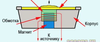
Fuses in car audio
All fuses in a car can be conditionally protected into two groups: a group of fuses in devices (for example, a radio and amplifier) and a group that protects wires from the source to the consumer. A very popular example of fuses that protect wires, so-called “circuit breakers” at home, at work, in general, everywhere.
Let's consider it as the most popular: the 16A “automatic” “cut out” - what happened? Most likely, consumers have exceeded the power calculated for them. Pmax = 220V*16A = 3520W = 3.52 kW or a more unpleasant situation - short circuit, i.e. passing the path with the least resistance, the resistance tends to zero, which means the current increases I=R/U. In the previous post I mentioned that the cable cross-section is related to the current strength. According to the Joule-Lenz law, the amount of heat released per unit time Q = I*I*R, leaving the current strength aside, we will see a direct dependence of Q on R i.e. The higher the cable resistance, the higher the heating, but the heating may be higher than safety standards.
If the current strength in the selected conductor exceeds a certain maximum permissible value, such strong heating is possible that the conductor can cause a fire in objects near it or melt itself. As a rule, when choosing wires intended for assembling electrical circuits, it is enough to follow the accepted regulatory documents that regulate the choice of conductor cross-section.
I’ll give you a table; if I’m not mistaken, it’s used at AZ competitions.
If, during your calculations, it turned out that the maximum rating of the fuse protecting the wiring turned out to be less than the rating of the fuse built into the connected device itself, then most likely you simply chose too small a cross-section of the supply wire.
Why are there so many fuses in cars?
Modern cars have quite a lot of fuses - this is done for safety, they are located in one place - for ease of maintenance. For example, non-working headlights - the fuse allows you to localize the fault, and if it constantly blows out, you should not install a fuse with a higher rating - you need to look for the cause.
Requirements
1) EVERY positive power cable you run from the battery should have a fuse as close to the battery as possible. According to the rules, the length of the wire is no more than 30 cm from the battery terminal.
2) The area from the battery terminal to the fuse is not protected and is a potential fire hazard. Therefore, it should be as short as possible, and its location should not threaten the integrity of the wire insulation.
3) Fuses cannot be installed on the negative wires.
4) Attach the fuse holder firmly to the body so that the wire along with the vibration fuse does not get caught in moving parts of the engine or anywhere else.
5) Place the fuse in an accessible place so that you do not have to disassemble the floor of the car to get to it; in addition, the installation site must be dry so that water does not get on the fuse.
6) If you are replacing the wire from the generator to the battery with a more powerful one, and placing it in potentially dangerous places, then it is highly advisable to provide it with a separate fuse near the battery with a rating close to the maximum current of the generator, EVEN if there is no fuse there on the factory wire.
7) ALL power wires must be additionally protected with corrugated or snakeskin.
Amplifier connection example
If you are installing more than one amplifier, you can connect them in two ways. The first is to stretch one thick wire, and then distribute power using distributors. If the wires from the distributor to the amplifiers turn out to be quite long (more than 40 cm) and are thinner than the main wire going to the battery, then use a distributor with built-in fuses, each with a rating corresponding to the cross-section of the thinner cable connected to it. They are needed to protect these sections of wiring with a smaller cross-section.
The second option is to run several wires from the battery, each to its own amplifier through a separate fuse. Despite the fact that this method at first glance seems more complicated, it has advantages: firstly, laying two thin cables is usually easier than one thick one, and secondly, the number of connections along the cable path in this option turns out to be less, which means that the resistance of the supply line will also be less.
Types of fuses in AZ
Flag fuse
To connect the head unit, you can use a regular flag fuse.
Since it will be located in the engine compartment next to the battery, choose a sealed holder for it.
AGU type fuses
AGU type fuses are the most common in amateur car audio installations due to the fact that they and their holders are cheaper. They are a glass cylinder with metal tips and a fusible insert in the middle. The main disadvantage of AGU type fuses is that they are made of several elements - metal tips and a fuse-link are connected to each other by contact welding, and under conditions of oxidation and vibration when installed on a car, they can fail.
In addition, the AGU type fuse in the holder is crimped with spring contacts, which is also unreliable.
Fuses type ANL
And for more powerful systems it is better to use ANL (flat) fuses. They are made from a single metal plate, which itself is a fusible link.
Such a fuse is securely bolted into the holder and the likelihood of vibration failure or oxidation is practically zero.
miniANL fuses
Just like ANL, fuses of the AGU type are free of disadvantages.
But unlike ANL, they are used with lower currents and are smaller in size than their counterparts.
Circuit breakers
An alternative to fuses is circuit breakers that trip when a specified current is exceeded.
Connecting the amplifier to the radio
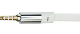
Connecting the amplifier to the radio is quite simple. It connects with two types of cables: RCA interconnect and Remote.
Make all connections on a de-energized system (positive wire folded away from the battery)!
Interconnect cable
To avoid interference, lay acoustic and signal cables on the opposite side of the power cables; if intersection cannot be avoided, do it at a right angle.
Interblocks or RCA connect to the linear outputs of the radio and transmit the audio signal to the amplifier. Line outputs have a left and right channel (can be mono for a subwoofer), do not confuse them when connecting to an amplifier, so as not to disrupt the balance adjustment on the radio (left/right).
Remote
The minimum cross-section wiring that transmits the signal to turn on the amplifier when the radio is turned on is the same when it is turned off. Usually the radio has a separate wire for this; if it doesn’t exist, you can connect to the active antenna control or connect it to a permanent plus by installing a toggle switch to independently control the amplifier. It is highly not recommended to power it from a constant +12 directly - this way your amplifiers will be constantly on, which will be an unnecessary load.
Types of protection
The rating of the protection device must correspond to the current-carrying capacity of the wire, which is determined by the cross-section and permissible operating temperature of the conductor insulation. The relationships between these quantities are summarized in tables. Therefore, it seems that having them, choosing a power fuse is not difficult. However, this can only be done correctly by knowing what it is intended for. For protection against short circuit or overload.
Short circuit protection
A short circuit is a condition in an electrical circuit in which current flows from a voltage source, but returns to it bypassing the intended load. A short circuit occurs due to damaged insulation or incorrectly connected equipment. The short circuit current is extremely high and is limited only by the power of the source and the resistance of the wires.
Short circuit protection is essential for conductors with approximately constant loads. The current strength in operating mode is less than the current-carrying capacity of such a conductor. And in the event of a short circuit, when the current increases many times and exceeds the rated current load, the fuse, which can withstand the high current for less than a second, does not allow the conductor to heat up, after which it melts and breaks the circuit.
Characteristics of fuses for the power wire:
The exact value of the shutdown current for the fuse protecting the wire during a short circuit is not important. A device with a rating equal to the current-carrying capacity of the wire is suitable. MIDI or ANL fuses are used for short circuit protection
Overload protection
Overload occurs when the motor, inverter is running, or more devices are plugged into sockets at the same time than intended. If the current in the circuit increases and remains at 110-150% of the rated current load of the conductor for a long time, then the wire and the protective device will heat up. And if the operating mode does not change, the accumulated heat will damage the wire. To prevent this from happening, the wires must be protected from overload.
Most fuses trip when the current is approximately 1.3 times their rating. Therefore, in order to limit continuous current and not allow it to heat the wire too much, the fuse rating is chosen equal to 80% of the current-carrying capacity of the conductor
In the tables, the current-carrying capacity is indicated for conductors located in open areas with good air circulation. Heat transfer is worse in cable ducts or inside partitions. Therefore, the wire will heat up to a critical temperature even when less current flows through it. If the wire is laid in a cable channel or inside a partition, before choosing a protection device, its current-carrying capacity is reduced
Suppose we need to protect a power wire with a cross-section of 25 sq. mm from overload, the insulation of which can withstand a temperature of 105 C. According to the table, the maximum permissible continuous current for this wire is 170 A. The fuses operate at a current of 130% of the nominal. Therefore, to protect the wire, you need a fuse rated 80% of 170A or 130 Amps. It will burn at a current of 1.3 x 130 A = 169 A.
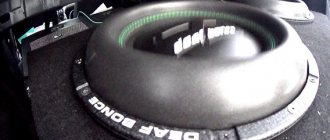
Proper nutrition from LOUD SOUND
1.
The main thing is nutrition. The audio system should start with it.
2.
The best power supply should come from the most
powerful amplifier
- usually the subwoofer amplifier
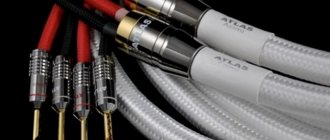
3. How to choose wire thickness?
It’s very simple - read 100,500 articles about choosing the thickness of the wire, complete the “auto audio school” courses, make complex calculations on a slide rule, and be sure to complete the “Theoretical Fundamentals of Electrical Engineering” course at some university.
Or choose this:
- up to 800 Watt – 4Ga (25kW),
- 800+ W – 2 Ga (35 kW),
- 1.5 kW and more - 0ga (50 kW)
We are talking about the total power of the system
. If you choose a wire that is too thick, it’s okay, if it’s too thin, there will be a loss of voltage from the beginning of the wire to the end. That is, under the hood there will be 12.5 Volts, on the monoblock 11.5 Volts - this is very, very high. not good, since in this case you not only risk burning the amplifiers, but also warm up the wire. And the thinner it is, the more it will warm up.
For clarity, if you power the amplifier with a thin wire, it will become red-hot. If at the same time it is in a silicone braid. Well, you understand.
4
.
A voltmeter
is
a must
. In any form, but you must know what is happening in the system on which tracks. At a minimum, you should measure the voltage after starting the audio system in two places:
- under the hood
- and on the largest consumer (usually a monoblock) -
The voltage should be the same and not drop below 12 Volts.
5.
Forget about capacitors (storage devices)
. The only benefit from a capacitor is a voltmeter, if it has one, but if not, the capacitor is only useful to the capacitor seller. The capacitor is not cheap - it’s better to buy a thicker wire or an additional battery
6
.
How to choose an additional battery?
Ideally, it should be exactly the same as under the hood, even better if they are
both new.
If it is not possible to install the same one, let them be of the same type:
- both AGM,
- or both lithium.
You can put an AGM together with acid, or even an AGM together with lithium - but a battery with a high voltage will be constantly in a state of discharge until the overall voltage levels out. In practice, I used AGM and acid many times and nothing happened in a year or more of use.
7.
How to connect
an additional battery? Relays, adapters - on. all this - just connect plus with plus and minus with minus.
8.
In addition to strong consumers,
do not forget about the weakest one - the GU
(radio tape recorder) - do not power it from the cigarette lighter or from random wiring on which you will find plus and minus.
Don’t be lazy - drag both the plus and minus from the same place where you got the power for the amplifiers. This way there will be a lower risk of interference and the radio will not turn off when you start the car.
9.
The generator is very important
.
If you skip a bunch of theory, you need to choose a generator like this: for every kilowatt of power you need an 80 A generator + 69-70 Ah battery.
This is, of course, an ideal picture, and often in systems consuming 4 kW there are standard 100A generators and a pair of batteries. But if the generator is not enough, the batteries will be constantly discharged while the music is playing and eventually the voltage will begin to drop.
How to measure wire diameter
The diameter of a thin wire is best measured with a micrometer. If you don’t have a micrometer at hand to measure the diameter of the wire, you can use an ordinary ruler.
You need to wind 10-20 turns per turn of wire on a ruler, divide the number of closed millimeters by the number of wound turns. Get the diameter. For example, I wound 10 turns of wire and they covered 6.5 mm. Divide 6.5 by 10. The diameter of the wire is equal to 0.65 mm. 0.05 mm is occupied by insulation. Therefore, the actual diameter is 0.6 mm.
Such a wire is suitable for making a 30 A fuse. The wire was wound thick for greater clarity. The more turns you wind on the ruler, the more accurate the measurement result will be. You need to wind at least one centimeter. If you have a short length of wire, then wind it around any rod, for example, a screwdriver, toothpick or pencil, and measure the width of the winding with a ruler.
| Online calculator for calculating wire diameter | |
| Winding width on the ruler, mm: | |
| Number of turns: | |
You can process the measurement results using an online calculator. To determine the diameter of the wire, just enter the winding width, the number of turns in the windows and click “Calculate wire diameter”.
Current breaking capacity
In the event of a short circuit, the main circuit breaker or fuse must break the circuit through which a very high current flows. If the protection device is not designed for this, an electric arc may occur, the contacts of the machine will weld together and the circuit will not open. The ability of a circuit breaker or fuse to trip during a short circuit is characterized by its current interrupting capacity (AIC).
AIC is the maximum current a device can cut at a given voltage. The expected short circuit current must not exceed the current breaking capacity. The short circuit current in 12 and 24 volt DC systems depends on the battery's cold cranking amps (CCA).
| Battery cold start current, A | Battery capacity, Ah | Current breaking capacity, A |
| 650 and less | 140 | 1500 |
| 651-1100 | 141-255 | 3000 |
| 1101 — 2200 | 256-500 | 5000 |
| Over 2200 | More than 500 | Equal to the short circuit current specified by the battery manufacturer or 100 x battery capacity |
The data presented in the table applies only to gel, AGM and liquid acid batteries. The short circuit current of some types of AGM and especially lithium batteries is significantly higher.
If the breaking capacity of the circuit breaker does not match the capacity of the battery, a fuse with an appropriate AIC is installed between the circuit breaker and the battery. For example, Class T (AIC - 20,000 A)
If the system voltage is less than the rated fuse (for >
For fuses rated less than 30 amps in a 12-volt electrical system and less than 15 amps in a 24-volt electrical system, the current breaking capacity is not required.
Doesn't turn on
One of the reasons why the tape recorder in the car does not work, although there is power, is a blown fuse. This can happen due to overload caused by listening to music at high volume for a long time or a short circuit in the speaker wiring. As a result of this malfunction, the radio refuses to turn on.
To fix the problem, remove the device and remove the fuse. Its rated current is 5 or 7.5 A. Since it is impossible to accurately determine by appearance whether the fuse is intact, the serviceability of this part is checked using a tester or multimeter.
If the car radio was connected through a car mounting block, then the integrity of the fuses in it should also be checked.
The next reason why the radio does not turn on is a break or chafing of the power wires. The contact in the standard block could also come loose due to contamination or loose connectors. To fix this problem, you should carefully inspect the wiring and connectors. Particular attention is paid to the connection of the receiver to ground or the car body. Broken wires should be replaced and connected as securely as possible.
The terminals on the connector must be thoroughly cleaned of dirt and securely crimped with pliers.
Incorrect connection also leads to the fact that the radio in the car does not turn on. To resolve this problem, you should carefully inspect the wiring. You can identify the wires coming from the battery using a test lamp. Wiring to speakers is often done with two-core cables.
In simple words about repairing TVs and home appliances with your own hands
Hello, friends!
This article is devoted to car radios, or more precisely, to the diagnosis of typical malfunctions of these devices.
The car radio is subject to constant vibrations while the car is moving, which only contributes to its rapid failure.
Typical car radio malfunctions include:
The car radio does not turn on at all. The reason for this may be lack of power. You can check the power yourself or by contacting a service center with an auto electrician. If the reason does not lie in the diet and everything is fine with it, it is necessary to carry out a diagnosis.
Lack or loss of control panel backlight. Reason: This malfunction may indicate that the light sources (LEDs or bulbs) or the power circuit of the control panel are not in order.
The car radio does not read at all (NO DISK or ERROR appears) or reads CDs or DVDs poorly. The cause of this malfunction may lie in the laser head, the motor that rotates the disk, or the main control board.
When the car shakes while driving (on a dirt road, for example), disk reading gets lost. Reason: this defect may be associated with a breakdown of the shock absorbers of the radio or laser head. The malfunction can be eliminated by carrying out repairs in a workshop.
The car radio is working properly, but there is no sound on one or all channels. It is necessary to check the performance of the speakers in a hospital service center. If everything is in order with the speaker, then the malfunction may be associated with a failure of the power circuits or the pre-amplifier of the car radio, as well as its output stage.
The message “Please code” appears. This means that the problem lies in the settings reset. To eliminate this, you need to enter the code for the head unit. Contact the service center.
CD/DVD car radios do not load or unload the disc. The cause of the breakdown may lie in the disk loading motor, its control, power supply, or in the pressure roller. As a result, the disc may slip and fail to grip. It's also worth checking the disc sensors.
Failures associated with the supply circuits can lead to the fact that the device will not turn on at all or there will be no functioning of any modes (no display backlight or no sound or CD mode). The absence of sound may indicate that the UMZCH has burned out. In such cases, check the protective fuse, inspect the printed circuit board, inspect the microcircuits for damage to the housing (deformation, chips or cracks). The electrolytic capacitors may be swollen or the traces may be burnt out.
If nothing is found visually, then it is better to contact a specialist, since attempts to fix the problem yourself can lead to even bigger problems.
I wish you success!
Why the radio does not turn on - solutions to the problem
Anyone who spends a lot of time behind the wheel knows that a car radio is a very important part in a car. Any trip is more enjoyable accompanied by your favorite music. Currently, there are many models of car radios to suit every taste and budget. They are equipped with various functions and can satisfy any motorist. Regardless of its cost, a car radio, like any other complex electronic device, can sometimes fail. It often happens that the car radio simply stops turning on, or turns on and immediately turns off. There may be several reasons for this malfunction.
Why doesn't my car radio turn on?
Main causes of malfunction:
to do it correctly depends on the car model and the receiver itself. The fuse is usually located on the back of the device and is blue in color.
Why does the radio turn on and off:
Why does the radio turn on by itself?
When installing any electrical equipment, including a radio, in a car yourself, you need to be very careful. Before installation, you must carefully study the instructions. Be sure to follow safety precautions while working. If installed incorrectly, not only may the radio malfunction, but also more serious problems associated with the vehicle's electrical system.
Parallel conductors
When a powerful device is connected to a battery located several meters away, the procedure for selecting the power wire may end up with its cross-section being unreasonably large. In this case, instead of one, two parallel conductors can be used.
Let's assume that a 12-volt bow thruster that draws 300 amps needs to be connected to the battery. The total length of the positive and negative conductors between the battery and the steering wheel is 15 meters.
According to the tables, we find that for a current of 300 A, a wire with a cross-section of 70 sq. mm and an insulation temperature of 105 C is suitable (current-carrying capacity outside the engine compartment is 330 A). But for a given length the voltage drop in the wire will be 10%.
Losses will decrease if the cross-section is increased from 70 to 95 or to 120 sq. mm. But such wires are more difficult to lay and connect. In addition, they simply may not be available. Therefore, instead of one, you can use two parallel wires of 70 sq. mm (two for the positive and two for the negative branches of the circuit. Four wires in total). In this case, the following conditions must be met:
- Both power wires must have the same length and cross-section. They must be laid in one cable channel or box
- The current-carrying capacity of each conductor must exceed the full load. This is necessary in order to avoid overheating if one of the wires for some reason stops conducting current.
- The rating of the protection device must be less than or equal to the current-carrying capacity of each conductor (in the example considered, no more than 330 A)
- If a single fuse is used to protect wires, then its rating should not exceed the current-carrying capacity of each of them. Additional precaution is necessary in case one of the wires for some reason stops conducting current. The second one will remain protected in this case. But if the fuse rating is selected based on the total current-carrying capacity of the conductors, then if one of them is disconnected, the protection device will not work.