Shouldn't we filter the input signal in a wide swoop to suppress interference relative to a single level at the required frequency, a given number of times different from the passband boundary? What about the calculation of active second-order polynomial filters on the Rauch, Salen-Key and biquadratic links? How about drawing a curve of changes in capacitance reactance depending on frequency?
“Stop being clever, point your finger!” I foresee the legitimate grumbling of a visitor who has fallen into temptation from the page title.
And indeed. I don't belong here! The bazaar needs to be filtered, not disgraced!
So let's get started. To begin with, we will look at active and passive low-pass filters, high-pass filters, and PFs without the use of inductors.
Let's define the terminology.
— A low-pass filter (LPF) is a device that passes low-frequency signals and blocks high-frequency signals. — A high-pass filter (HPF) accordingly passes high-frequency signals and delays low-frequency signals. — A bandpass filter (BPF) passes signals in a certain frequency band and suppresses signals at both low and high frequencies. — The passband is defined as the frequency range in which the frequency response of the filter does not go beyond the specified unevenness (usually 3 dB). — The filter cutoff frequency is the frequency at which the signal attenuation reaches -3 dB on a logarithmic scale, or 1/√2 ≈ 0.71 on a linear scale. — Frequency response unevenness in the passband—the size of the frequency response fluctuation from peak to peak in the passband. — The slope of the filter’s frequency response is the rate at which the frequency response decays in the suppression band (dB/octave or dB/decade).
Let's start with the simplest first-order RC filters. On the left is a low-pass filter (LPF), on the right is a high-pass filter (HPF).
The slope of the frequency response of such filters in the suppression band is 6 dB/octave. The cutoff frequency is calculated using the formula:
Now we need to decide on what considerations to choose the ratings R and C. The capacitance is calculated by our plate, and the choice of resistor resistance, in order to achieve the declared steepness, must be approached with all responsibility. The value of this resistor should be an order of magnitude greater than the output impedance of the previous stage and an order of magnitude less than the input impedance of the subsequent one.
Low Pass Filter (LPF) - also known as an integrator:
Low-pass filter is a filter that passes frequencies below the cutoff frequency (f) without changing and suppresses frequencies above f. At the cutoff frequency it has an amplitude value of -3dB. This is a first order filter and the cutoff slope is 6dB/octave. Most often, such filters are used to cut off high-frequency interference and noise.
An octave is a frequency interval in which the final frequency value is twice as large as the initial frequency.
Low Voltage Capacitors for Power Electronics
Low-voltage (relatively, of course, “only” 230...1000 V) applications of capacitors include, first of all, compensation of voltage drops and filtering of harmonics in systems using power frequency currents (50...60 Hz). Designed to work with voltages in the range of 230...1000 V with energy levels of the order of 2.5...56.2 kVar for aluminum housings and up to 500 kVar in a steel housing. They are produced in series for indoor use - PhMKD and for outdoor conditions - PhMKDg (Fig. 3).
Rice. 3. Low voltage capacitors for power electronics
The advantages include low loss coefficient, compact size, good dissipation of excess heat, long MTBF (over 150,000 hours), compliance with EN 60831/1 and 2, EIC 60831/1 and 2 standards.
High Pass Filter (HPF) - also known as a differentiator
A high-pass filter is a filter that attenuates frequencies below the cutoff frequency (f0) and transmits frequencies above f without changing. Just like the low-pass filter above, the signal at the cutoff frequency has an amplitude of -3 dB, and a cutoff slope of 6 dB per octave.
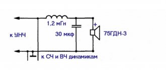
Both the low-pass filter and the high-pass filter work as a voltage divider, in which one arm is represented by a constant resistor, and the second by a capacitor, which has a frequency dependence.
Such filters are often used at the outputs of audio amplifiers to cut off infra-low frequencies that can damage speakers.
Introduction
The frequency characteristics of capacitors are important parameters that are required for circuit design. Understanding the frequency characteristics of a capacitor will allow you to determine, for example, what noise a capacitor can suppress or what power supply voltage fluctuations it can control. This article describes two types of frequency responses: |Z| (impedance or total resistance) and ESR (capacitor equivalent series resistance).
The impedance Z of an ideal capacitor is given by formula 1, where ω is the angular frequency and C is the capacitance of the capacitor.
Figure 1. Ideal capacitor
(1)
From formula 1 it is clear that as the frequency increases, the impedance of the capacitor decreases. This is shown in Figure 1. In an ideal capacitor there is no loss and the equivalent series resistance (ESR) is zero.
Figure 2. Frequency response of an ideal capacitor
In a real capacitor (Fig. 3), there is some resistance (ESR) caused by dielectric losses, capacitor plate resistance losses and losses associated with leakage resistance, as well as parasitic inductance (ESL) of the capacitor leads and plates. As a result, the impedance frequency response takes on a V-shape (or U-shape depending on the type of capacitor), as shown in Figure 4. The figure also shows the ESR frequency response.
Figure 3. Real capacitor
Figure 4. Example of the frequency response of a real capacitor
The reason why graphs |Z| and ESR have the same form as in Figure 4, can be explained as follows. Low frequency region |Z| in this region decreases inversely with frequency, as in an ideal capacitor. The ESR value is determined by the dielectric loss in the capacitor. Resonance Region As the frequency increases, the ESR, as a result of stray inductance, electrode resistance and other factors, causes a deviation of |Z| from the ideal characteristic (red dotted line) and reaches the minimum value. The frequency at which |Z| reaches a minimum, is called the natural resonant frequency and at this frequency |Z| =ESR. After exceeding the natural resonance frequency, the element characteristic changes from capacitive to inductive and |Z| starts to rise. The region below the natural resonant frequency is called the capacitive region, and the region above is called the inductive region. In the resonance region, losses on the electrodes are added to the dielectric losses. High-frequency region With a further increase in frequency, the characteristic |Z| determined by the parasitic inductance of the capacitor. In the high-frequency region |Z| increases in proportion to frequency, according to formula 2. As for ESR, skin effect, proximity effect and others begin to appear in this area.
(2)
So, we looked at the frequency response of a real capacitor. The important thing to remember here is that as the frequency increases, ESR and ESL can no longer be ignored. Since there are a large number of applications in which capacitors are used at high frequencies, ESR and ESL become important parameters that characterize a capacitor in addition to its capacitance value.
The parasitic components of real capacitors have different meanings depending on their type. Let's look at the frequency characteristics of different capacitors. Figure 5 shows plots of |Z| and ESR for 10 µF capacitors. All capacitors, except film ones, are planar (SMD).
Figure 5. Frequency characteristics of different types of capacitors.
For all types of capacitors |Z| behaves the same up to 1 kHz. After 1 kHz, the impedance increases more strongly in aluminum and tantalum electrolytic capacitors than in monolithic ceramic and film capacitors. This is due to the fact that aluminum and tantalum capacitors have high electrolyte resistivity and high ESR. Film and monolithic ceramic capacitors use metal materials for the electrodes and hence have very low ESR. Monolithic ceramic capacitors and film capacitors show approximately the same characteristics up to the point of self-resonance, but monolithic ceramic capacitors have a higher resonant frequency and |Z| in the inductive region below. These results show that the impedance of SMD type monolithic ceramic capacitors is of small importance over a wide frequency range. This makes them most suitable for high frequency applications.
There are also several types of monolithic ceramic capacitors, made of different materials and having different shapes. Let's look at how these factors affect frequency response. ESR ESR in the capacitive region depends on the dielectric loss caused by the dielectric material. Class 2 dielectric materials based on ferroelectrics have a high dielectric constant and, as a rule, a high ESR. Class 1 materials - temperature-compensated materials based on paraelectrics - have low dielectric losses and low ESR. At high frequencies in the resonant and inductive regions, in addition to the resistance of the electrode material, their shape and the number of layers, the ESR depends on the skin effect and the proximity effect. Electrodes are often made of Ni, but for cheap capacitors Cu is sometimes used, which also has low resistance. ESL The ESL of monolithic ceramic capacitors is highly dependent on the internal structure of the electrodes. If the dimensions of the internal electrodes are given by length, width and thickness, then the inductance ESL can be determined mathematically. The ESL value decreases when the capacitor electrodes are shorter, wider and thinner. Figure 6 shows the relationship between the nominal capacitance and the resonant frequency of various types of monolithic ceramic capacitors. You can see that as the capacitor size decreases, the natural resonant frequency increases and the ESL decreases for the same capacitance values. This means that small capacitors with short lengths are better suited for high frequency applications.
Figure 6.
Figure 7 shows a reverse LW capacitor with short length L and large width W. From the frequency characteristics shown in Figure 8, it can be seen that the LW capacitor has lower impedance and better performance than a conventional capacitor of the same capacitance. With LW capacitors you can achieve the same performance as conventional capacitors, but with fewer components. Reducing the number of components reduces costs and reduces installation space.
Figure 7. External view of the reverse LW capacitor.
Figure 8. |Z| and ESR of reverse LW capacitor and general purpose capacitor
Based on materials from Murata. Free translation
High Voltage Capacitors for Power Electronics
Main purpose:
- Shunt capacitors;
- Harmonic filtering;
- Series capacitors;
- Capacitors for static reactive power compensation;
- Capacitors for high-voltage DC power lines;
- Voltage limiters and filters.
Vishay high voltage capacitors are available up to voltage levels of 24 kV and power levels up to 900 kVar. Banks of capacitors are also offered that allow operating voltages up to 800 kV.
Available in versions with one and two contact sleeves, single- and three-phase capacitors are offered (Fig. 4).
Rice. 4. High voltage capacitors for power electronics
Design solutions make it possible to combine individual capacitors into banks and capacitor fields with protection against phase imbalance.
Literature
1. Vishay - Vishay ESTA - Vishay Brands // https://www.vishay.com/company/brands/esta/
2. Power Capacitors // www.vishay.com/docs/49631/49631_vmn-pl0332-1104.pdf
3. Vishay - Capacitors - Induction Heating // https://www.vishay.com/capacitors/hcp-ind-heating/
4. Vishay - Capacitors - Power Electronic// https://www.vishay.com/capacitors/app-power-electronic/hcp-power-elec/
5. Vishay - Capacitors - Low voltage AC// https://www.vishay.com/capacitors/app-low-voltage-ac/hcp-low-volt-ac/
6. Vishay - Capacitors - Ph... Power Capacitors - High Voltage Power Capacitors https://www.vishay.com/capacitors/list/product-13045/
7. Vishay - Capacitors - HV Power Supplies // https://www.vishay.com/capacitors/app-hv-power-supplies/hcp-hv-power-supplies/.
Obtaining technical information, ordering samples, delivery - e-mail
Vishay Precision Group Inc. launched VHZ Hermetic (Z-Foil) - a new series of ultra-precision resistors in a hermetic package
The offered products have the following applications: primary and secondary rectification, feedback in operational amplifiers, precision voltage dividers, measuring instrument shunts.
Specifications:
- TCS value ±0.2ppm/°C (-55…125°C)
- Nominal loss after 10,000 hours of operation (0.15W; 70°C) no more than 0.005%
- Ratings 5 Ohm…121 kOhm
- Ordering a non-standard denomination (1K2345) does not affect the cost of production
- Electrostatic voltage resistance 25kV
- Power dissipation 0.6W at 70°C; 0.3W at 125°C
- Induced thermoEMF 0.1 μV/°C
- Non-inductive and capacitive housing
- Current noise level less than -40dB
- Nominal deflection under voltage less than 0.1ppm/V
- Stabilization of the nominal value within 1 s after shock temperature exposure (nominal loss 10ppm)
- Parasitic inductance is less than 0.08 μH.
Vishay Intertechnology Inc. launched new series of low-profile inductors in the 1212 form factor of the IHLP series
The offered products have a maximum operating frequency of 1 MHz, operating temperature range -55…125°C.
Applications: DC/DC converters, distributed power systems, FPGA power supply in electronic devices.
IHLP-1212AB-11:
- Ratings 0.22…0.56 µH
- Saturation current range 6.7…9.3A
- DC resistance 9.5…18.7 mOhm
IHLP-1212AE-11:
- Ratings 0.22…1 µH
- Saturation current range 5.3…9A
- DC resistance 9.5…29.5 mOhm
•••
Capacitors for high voltage power supplies
High voltage power supplies are used in medical imaging systems, CRT monitors, electrostatic coating (automotive), and electrostatic precipitators (industrial).
Vishay high-voltage capacitors comply with the standards EN 50176, EN 50177, EN 50223, EN 50348. DC operating voltage ranges 1...100 kV (Fig. 5).
Rice. 5. Capacitors for high voltage power supplies
Capacitors are a compact, flexible, reliable solution for high-voltage power supplies for a wide range of applications and industries. Available as high-voltage systems of the BG 1971-000-9000A, BG 1971-000-9700 and BG 1972-6100-010, BG 1972-6123-01 series.
BG 1971-000-9000A, BG 1971-000-9700 - compact devices with an integrated control board for liquid paint or powder coating systems. Supply voltage 30 V at current consumption 1.5...5 A, output voltage up to 100 kV, current 250...500 µA.
BG 1972-6100-010, BG 1972-6123-01 - compact high-voltage generators in a cylindrical housing with a supply voltage of 1...24 V and an output voltage of up to 100 kV.