Maxim Zhukov 03/04/2020
51570
In this article we will look at what types of plugs there are.
, what is pinout (mini jack and not only), and what types exist.
We will also consider repairing the headphone plug and soldering a 3.5 mm mini jack. All this is not at all difficult, the main thing is to know just a couple of nuances. ⭐ Best wired headphones (2022):
Pinout of the wire of the 3.5 connector (Jack) with and without a microphone.
Nowadays, the pinout of headphone wires with a microphone shown in the first picture below is generally used everywhere, but there is also another one, which is mainly used on old phones and in phones from some manufacturers. They differ in that the microphone and ground contacts are swapped.
If you have resoldered the headphone plug and you have a quiet sound in the headphones, and when you press the headphone call button the volume in the headphones increases, then you should resolder the ground and microphone wires (swap them).
Pinout 3 5 mm jack 4 pins
Pinout 3 5 mm jack with 3 pins
Cable cutting.
You can prepare a cable in different ways, but the least traumatic method for conductors is to remove the insulation using a soldering iron.
Holding the soldering iron with one hand, rotate the shielded wire around its axis with the other hand, while pressing the insulation against the sharp edge of the soldering iron tip. https://oldoctober.com/
If after this you cannot remove the insulation by hand, you can use side cutters.
It should look something like this.
We also remove insulation from individual wires in the same way.
Now you can give the cable a look suitable for tinning.
Return to top to table of contents.
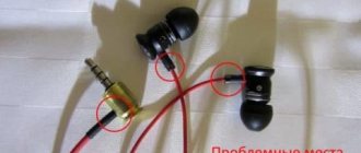
What to do if your headphones don't work. DIY headphone repair.
We will need a knife, a soldering iron, solder, rosin, cut off 5-10 cm of wire from the plug, remove all the insulation from the plug, just in case, remember the sequence of wires by color (sometimes they are different). Strip the wires and solder them to the 3.5 mm jack. I advise you to fill the soldering area with hot glue (hot glue) and compress it with heat shrink, so the connection will last much longer. The wires will not solder well, but I advise you to warm them up longer, and you will succeed. Also see USB cable pinout.
3.5mm Jack Can be purchased from the links below.
Link #1
Link #2
Link #3
Four-wire plug
There are two different options here.
- Ordinary headphones without a microphone and control buttons. 4 wires are connected to the plug: a minus from each copper-colored speaker and a plus (blue with red or green with red). For convenience, the negatives are twisted into one bundle and the result is three wires that need to be soldered to their specific places.
- Headset with microphone. Here the plug has 4 types of contacts: one from each speaker, one for the microphone, and there is room left for soldering a common wire or ground. Schematically, such soldering looks like this:
Applications [ edit | edit code ]
Analog audio [edit | edit code ]
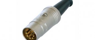
3/180° and 5/180° connectors were initially standardized and widely used in Germany, Czechoslovakia and, later, in the USSR and CMEA countries for connecting analog audio equipment, such as a stereo tape recorder with a stereo amplifier or preamplifier. Four contacts were used for the signal and a fifth for the common wire. The patch cords had a connector at each end, and the contacts were connected one-to-one: contact 1 with contact 1, 2 with contact 2, etc. The contacts on the plugs are numbered (from right to left, looking from the outside of the connector, contacts up ): 1-4-2-5-3. The holes in the sockets are also numbered 1-4-2-5-3, but from left to right (looking at the holes). This numbering is used because the base was a three-pin connector with a natural numbering of 1-2-3, and then pins 4 and 5 were added to it. Since a three-pin plug can be inserted into a five-pin socket, the numbers of the connecting pins are the same.
A four-channel wire wired in this way is sometimes simply called a DIN cord.
,
DIN wire
or
DIN cable
. For mono connections, 3/180° plugs are sufficient. When a mono plug is inserted into a stereo jack, it connects to the left channel, which is why some stereo equipment had mono/stereo switches. Such an interface was rare in the US market and gradually disappeared from new equipment, both in Germany and around the world, giving way to RCA (tulip) connectors. DIN connectors are still used in Naim Audio devices [6].
| Application | Connector | Assigning contacts | |||||
| 1 | 4 | 2 | 5 | 3 | |||
| amplifier | mono | 5/180° | sound output | screen/general | audio input | ||
| stereo | left channel output | right channel output | right channel input | left channel input | |||
| record player | mono | 5/180° | audio input | screen/general | sound output | ||
| stereo | left channel input | right channel input | right channel output | left channel output | |||
Other uses[edit | edit code ]
5/180° connectors were often used for:
- SYNC interface for electronic musical instruments;
- interface M >[7][8] );
- connecting two controllers of radio-controlled models for training purposes.
The DIN connector has seen other applications in its time besides audio. The TurboGrafx-16 game console used a 5-pin DIN connector for video and audio output. The Atari XEGS, along with the Commodore C64 and BK, used a DIN connector to connect to the power supply. Also, early C64s that only supported composite video output used a 5-pin DIN for video and audio, but newer C64s that supported chrominance/luminance output used an 8-pin DIN to carry additional signals. The Neo Geo and Neo Geo CD used an 8-pin DIN for composite video, RGB video, and mono audio outputs, as well as +5 V to power the RF modulator [9]. Dragon 32 computers used 4 5-pin DIN connectors for joysticks, tape recorder and monitor output. The TRS-80 Model I used three identical 5-pin DIN connectors for the power supply, video output and tape recorder, which made it easier to destroy the device if connected incorrectly. Much the same thing was observed in Soviet BC computers, which used four 5-pin DIN connectors for tape recorder, black and white video, RGB color video and power supply.
Soviet ONTs-VG connectors [edit | edit code ]
In the Soviet Union, 3- and 5-pin DIN connectors, called ONTs-VG, were used everywhere. The 5-pin connector was also called SSh-5, SG-5 (Ш - plug, G - socket), and the three-pin connector - SSh-3, SG-3. Initially, this was factory audio equipment, but then radio amateurs and cooperatives fell in love with this method of connecting equipment, and began installing such connectors in almost any device that dealt with low-frequency signals. It is impossible to talk about standard wiring of such connectors. While 3- and 5-pin connectors could be easily purchased, the situation with the rest was difficult. 4-pin connectors were not seen anywhere, neither on the equipment nor for sale. Six- and 7-pin connectors were difficult to obtain, and 8-pin connectors were very exotic.
As an example, we can mention the Soviet color TV “Raduga-315” with a 51 cm diagonal kinescope. It used a standard DIN-6 connector to connect a video signal source (for example, a VCR). Due to the fact that the signal playback mode on the TV was turned on with a separate button, a cable with an accessible SSH-5 connector was used to connect the VCR to the TV, the outer terminals of which 1 and 3 were simply bitten off with wire cutters, which ensured mechanical compatibility with the socket on the TV.
Since there were many non-standard ways to use connectors, only the standard ones are mentioned in the table.
| Contacts | Drawing | Fork | Socket | Standardized Application |
| 3 | ONTs-VG-2-Z/16-V | ONTs-VG-2-3/16-R | Monophonic connection of tape recorders to amplifiers, radios, microphones to tape recorders. Another name: SSH-3. | |
| 4 | Unknown | Unknown | Quite popular in the military industry. Other names: gx16 16m 4 | |
| 5 | ONTs-VG-4-5/16-V | ONTs-VG-4-5/16-R | Stereophonic and monophonic connection of tape recorders to amplifiers, radios, microphones to tape recorders, headphones to amplifiers. Other names: SSh-5, SG-5, DIN 41524, “5-pin DIN 180°”, DIN-5/180°. | |
| 5 | ONTs-VG-11-5/16-V | ONTs-VG-11-5/16-R | Headphones (plug) and equipment output for connecting them (socket) (not used since 1988) [10]. | |
| 5 | Unknown | ONTs-VG-11-6/16-V | ONTs-VG-11-6/16-R | Connecting VCRs to TVs. The direction of the signal is changeable, along each audio and video wire in two directions, depending on the “record/playback” mode. In the future, there will also be connection of household computers to TVs (black and white or composite signal). |
| 7 | ONTs-VG-11-7/16-V | ONTs-VG-11-7/16-R | Wired remote control for equipment. | |
| 8 | ONTs-VG-5-8/16-V | ONTs-VG-5-8/16-R | Connecting a car stereo to a car radio. Connecting a home computer and other RGB signal sources to a TV. |
Other examples of headset jack wiring
Here, without looking or checking, you can solder two gold wires together
It's just that each channel has its own wire for ground. From an audiophile point of view, this option is more correct than one ground wire and contributes to a wider stereo base.
In general, it turns out that the whole problem of repairing the headset connector comes down to determining where the ground is that needs to be twisted to get 4 wires.
I repeat once again - the earth is always yellow. Also, mixtures of yellow with other colors are usually also earth.
Pinout diagrams by manufacturer
Apple audio pinout
- 1 - left
- 2 - right
- 3 - ground
- 4 - microphone
iPod Nano (4th, 5th Gen), iPhone (1st, 2nd, 3rd, 4th Gen), iPod Shuffle (3rd Gen), Cell Phone Connection iPhone headphone (handsfree)
Lenovo audio pinouts
1 - left 2 - right 3 - ground 4 - microphone
Lenovo Thinkpad Edge & X Series Notebook audio
Samsung audio pinouts
1 - left 2 - right 3 - ground 4 - microphone
Samsung Galaxy S I9000, S8500 Wave headset EHS60AVNBE / EHS60ANNWEGSTA / EHS60ANNBECSTD/ GH59-09752A headset Samsung Galaxy S2 i9100 headset should be compatible with Samsung Galaxy Note N7000, Samsung Galaxy Tab GT-P1000, P7100 Galaxy Tab 10.1, 4G LTE, C3530 , 350, Galaxy 551 i5510, Galaxy 550 I5500, E2330, I100 Gem, i220 Code, i350 Intrepid, I9003 Galaxy SL, I9100 Galaxy S II, i997 Infuse 4G, Google/Samsung Nexus S I9023/I9020, 335 S3350, Galaxy mini S5570, Wave 525 S5250, Star II S5260, Wave II S8530, S5780 Wave 578, Wave 533 S5330, Galaxy Gio S5660, Wave 723 S7230, Galaxy Ace S5830, Galaxy Fit S5670, Galaxy S 4G, Galaxy S WiFi 5.0, R910 Galaxy Indulge, S3850 Corby II , M190 Galaxy S Hoppin, M210S Wave2, M220L Galaxy Neo, M580 Replenish, C6712 Star II DUOS
Samsung i300, i330, i500, i700 handsfree/headset connector
Samsung OEM EHS64 Headset for Samsung Galaxy SIII GT-i9305 and some others
Samsung Series 9 Notebook headset (NP900X3D-A02DE)
Samsung SPH-a420, a580, a640, m220, m240, m300, m320, m330, Rant m540, Exclaim m550 SCH-R451C headset Samsung headset P/N: AEP010SLEB/STD
Samsung SPH-A880, SCH-U620, SCH-U540, SPH-M500, SCH-A950, SCH-A870, SCH-A930, SPH-A920, SPH-A940, SCH-A970, SPH-A900 BLADE, A900M, SCH- A990, SCH-U740 AEP204VBEB/STD Headset/Music
In some Samsung models, the ground contact and microphone can be swapped!