In everyday life, a powerful power source with a fixed voltage is often needed. It can be used as a charger, to power audio equipment (amplifiers), etc. It is advisable to make such power supplies using a pulse circuit. This circuitry allows you to create lightweight and powerful DC voltage sources. The complexity of the circuit begins to fade into the background compared to its advantages already at load currents of more than 2A. You can make a switching power supply with your own hands if you have the equipment and certain qualifications.
Types and principle of operation of switching power supplies
The basic operating principle of a switching power supply (SMPS) is that direct voltage (rectified mains voltage or from a third-party source) is converted into pulsed voltage with a frequency of up to hundreds of kilohertz. Due to this, the winding parts (transformers, chokes) are light and compact.
Fundamentally, IIPs are divided into two categories:
- with pulse transformer;
- with storage inductance (it can also have secondary windings)
The former are similar to conventional transformer mains power supplies; their output voltage is regulated by changing the average current through the transformer winding. The latter work on a different principle - they are regulated by changing the amount of accumulated energy.
Based on other characteristics, IIP can be divided into unstabilized and stabilized, unipolar and bipolar, etc. These features are not of such a fundamental nature.
Design verification
Before turning on the power supply for the first time, you need to check it. First of all, the installation is checked; for example, traces of soldering or unwashed flux could remain. Any component installed on the board may be faulty.
If everything is in order with the installation, you can proceed to the second stage of testing using a light bulb. Any incandescent lamp can be used as a light bulb. To do this, we connect the power supply we made in series with the light bulb, as shown in the figure below.
If the light does not light, it means there is an open circuit in the power supply circuit. You need to check the board tracks, inductor, diode bridge.
The light is constantly on. There is a short circuit in the power supply. The reason may be a breakdown of capacitors or transistors. It is also necessary to check the tracks of the printed circuit board and the output circuits of the transformer.
If the light flashes and goes out, it means the power supply is working and the capacitors are charged.
Structural and schematic diagram of the main parts of the block
Generalized block diagram of a pulse power supply.
A surge filter is installed at the input of the power supply. In principle, it does not affect the operation of a homemade or industrial switching power supply - everything will function without it. But you cannot abandon the filtering circuit - due to the extremely nonlinear shape of the consumed current, pulsed sources intensively “sprinkle” interference into a 220-volt household network. For this reason, devices running on the same network on microprocessors and microcontrollers - from electronic watches to computers - will malfunction.
Network filter circuit.
The purpose of the input device is to protect against two types of interference:
- common-mode (asymmetrical) – occurs between any wire and the ground (case) of the power supply unit;
- differential (symmetrical) – between the power wires (poles).
The filter, like the entire power supply, is protected at the input by fuse F (fuseable or self-recovering). After the fuse there is a varistor - a resistor whose resistance depends on the applied voltage. As long as the input voltage is normal, the resistance of the varistor is high and it has no effect on the operation of the circuit. If the voltage increases, the resistance of the varistor drops sharply, which causes an increase in current and the fuse burns.
Capacitors Cx block differential noise at the input and output of the filter in the range up to 30 MHz. At a frequency of 50 Hz their resistance is high, so they do not affect the mains voltage. Their capacitance can be selected from 10 to 330 nF. Resistor Rd is installed for safety - the capacitors are discharged through it after the power is turned off.
Common-mode interference is suppressed by a filter on Cy and L. Their values for the cutoff frequency f are related by the Thompson formula:
f=1/(2*π*√L*C) , where:
- f – cutoff frequency in kHz (the conversion frequency of the pulse generator is taken);
- L – inductance of the inductor, μH;
- C – capacitance Cy, µF.
The common mode choke is wound on a ferrite ring. The windings are identical, winding on opposite sides.
Common mode choke design.
Unlike the output filter, the rated current of the power supply unit does not affect the calculation of the noise protection filter elements, with the exception of the wire with which the inductor is wound.
After the filter, the mains voltage is rectified. In most cases, a standard full-wave bridge rectifier is used.
The principle of operation of the SMPS and its design
A switching power supply is a device that operates on the principle of an inverter, that is, it first converts alternating voltage into direct voltage, and then again converts it into an alternating voltage of the desired frequency. Ultimately, the last stage of the converter is still based on voltage rectification, since most devices still operate at a reduced DC voltage. The essence of reducing the size of these power supply and converting devices is based on the operation of the transformer.
The fact is that the transformer cannot operate with constant voltage. Simply, an EMF (electromotive force) will not be induced at the output of the secondary winding when direct current is supplied to the primary. In order for voltage to appear on the secondary winding, it must change in direction or magnitude. Alternating voltage has this property; the current in it changes its direction and magnitude with a frequency of 50 Hz. However, in order to reduce the size of the power supply itself and, accordingly, the transformer, which is the basis of galvanic isolation, it is necessary to increase the frequency of the input voltage.
At the same time, pulse transformers, unlike conventional linear ones, have a ferrite core of the magnetic circuit, and not a steel core made of plates. And also modern power supplies working on this principle consist of:
- mains voltage rectifier;
- a pulse generator operating on the basis of PWM (pulse width modulation) or a Schmitt trigger;
- DC stabilized voltage converter.
After the mains voltage rectifier, a pulse generator using PWM generates it into alternating voltage with a frequency of about 20–80 kHz. It is this increase from 50 Hz to tens of kHz that makes it possible to significantly reduce both the dimensions and weight of the power source. The upper range could be larger, however, then the device will create high-frequency interference, which will affect the operation of radio frequency equipment. When choosing PWM stabilization, it is imperative to also take into account the higher harmonics of the currents.
Even when operating at these frequencies, these pulsed devices produce high-frequency noise. And the more of them in one room or in one enclosed space, the more of them there are in radio frequencies. To absorb these negative influences and interference, special noise suppression filters are installed at the input of the device and at its output.
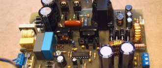
This is a clear example of a modern switching power supply used in personal computers.
A - input rectifier. Half-bridge and full-bridge circuits can be used. Below is an input filter having inductance; B - input smoothing capacitors with a fairly large capacitance. To the right is a heatsink for high-voltage transistors; C - pulse transformer. A radiator for low-voltage diodes is mounted to the right; D - output filter coil, that is, group stabilization choke; E - output filter capacitors. The coil and large yellow capacitor below E are components of an additional input filter mounted directly on the power connector, and not part of the main circuit board.
If a radio amateur invents a circuit himself, he must look into the reference book on radio components. The reference book is the main source of information in this case.
We recommend reading: Luminous intensity: what it is, how it is measured, power, formula, luminous flux
Inverter circuits
The resulting rectified voltage is supplied to the converter (inverter). It is performed on bipolar or field-effect transistors, as well as on IGBT elements that combine the properties of field-effect and bipolar ones. In recent years, high-power, low-cost insulated gate field-effect transistors (MOSFETs) have become widespread. It is convenient to build key inverter circuits on such elements. Switching power supply circuits use various options for connecting MOSFETs, but push-pull circuits are mainly used due to their simplicity and the ability to increase power without significant modifications.
Push-pull scheme
Push-pull converter circuit.
A push-pull inverter (push - push, pull - pull) is an example of a push-pull converter. Transistor switches operate on the primary winding of the transformer, consisting of two half-windings I and II. The transistors open alternately for a given period of time. When the top transistor in the circuit is open, current flows through half-winding I (red arrow), when the second one flows through half-winding II (green). To avoid a situation where both switches are open (due to the finite speed of the transistors), the control circuit creates a pause called Dead time.
Transistor control taking into account Dead time.
This circuit works well at low supply voltage (up to +12 volts). The downside is the presence of surges with an amplitude equal to twice the supply voltage. This entails the use of transistors designed for twice the voltage.
Bridge circuit
The push-pull bridge is free from the main drawback of the previous scheme.
Push-pull bridge inverter circuit.
Here, a pair of transistors T1 and T4 , then T2 and T3 (the key control signal is generated taking into account Dead time). In this case, the primary winding is connected to the power source first on one side, then on the other. The pulse amplitude is equal to the full supply voltage, and there are no voltage surges. The disadvantages include the use of four transistors instead of two. In addition to increasing the size of the power supply, this leads to doubled voltage losses.
Half bridge circuit
In practice, a half-bridge inverter circuit is often used - to a certain extent, a compromise between the previous two circuits.
Half-bridge circuit.
In this case, one side of the winding is switched by alternately opening transistors T1 and T2, and the other is connected to the midpoint of the capacitive divider C1, C2. Advantages of the scheme:
- unlike push-pull, there are no voltage surges;
- unlike bridge, only two transistors are used.
On the other side of the scale, the transformer winding is powered by only half the supply voltage.
Single-ended circuits
In the circuitry of converters, single-cycle circuits are also used - forward and flyback. Their fundamental difference from push-pull ones is that the transformer (more precisely, its primary winding) simultaneously serves as a storage inductance. In flyback circuits, energy is accumulated in the primary winding during the open state of the transistor, and is transferred to the load through the secondary winding during the closed state. In direct thrusters, energy accumulation and release to the consumer occur simultaneously.
Two phases of operation of a flyback single-cycle inverter.
How to assemble: step by step instructions
For those who want to assemble a switching power supply with their own hands, here are several assembly diagrams.
Let's consider the circuit of a switching power supply with a power of up to 2 W. The rectifier and filter in it are assembled on resistor R1 (from 25 to 50 Ohms), diode VD1 and capacitor C1 (20.0 μF, 400 V). The high-frequency converter is a self-oscillator assembled on transistor VT1, transformer TR1, frequency-setting circuit resistor R2 (470 kOhm) and capacitor C2 (3300 pF, 1000 V). The voltage removed from the output winding of the transformer is rectified by diode VD2 and smoothed by electrolytic capacitor C3 (47 pF, 50 V).
Any transformer from a non-working transformer used in charging a mobile phone or other low-power power source will be suitable as a core for a transformer. Winding occurs in the following order:
- first we wind 200 turns of the primary winding with copper wire with a cross section of 0.08-0.1 mm;
- we isolate the primary winding and wind 5 turns of the base winding with the same wire;
- We wind the secondary winding. Wire diameter – 0.4 mm. The number of turns depends on what voltage you need to get at the output at the rate of one turn per volt.
We recommend reading: What is a voltage divider and where is it used?
Expert opinion Alexey Bartosh Specialist in repair and maintenance of electrical equipment and industrial electronics. Ask a question Attention! There should be a small non-magnetic gap between the halves of the magnetic core. Usually it is already present on cores taken from smartphone charger transformers. If there is none, place a layer of paper between the core halves.
We tighten the finished transformer with electrical tape or tape.
Let's consider a single-cycle power supply made using a self-excited self-oscillator circuit. Output voltage – 16 V, device power – 15 W.
At the input of the device, the alternating voltage of the electrical network is rectified using a diode bridge assembled on diodes D1-D4 (you can use any diodes rated for a voltage of 400 V and a current of 0.5 A, for example, N4007). Capacitor C1 (20 µF, 400 V) is responsible for smoothing out ripples. To prevent current surge when turned on, resistor R1 (25-50 Ohms) is used.
The initial bias based on transistor T1 (you can use 13003 or 13005) is set by resistor R2 (470 kOhm) and diode D6 (N4007). To smooth out voltage surges that occur when T1 is closed, the circuit includes elements such as: capacitor C2 (3300 pF 1000 V), diode D5 (N4007) and resistor R3 (30 kOhm 1 W, or you can use two 15 kOhm resistors).
The positive feedback pulses necessary to maintain the self-oscillation mode are supplied to the base T1 through resistor R4 (150 Ohm) and capacitor C3 (47 pF, 50 V). A chain consisting of T2, R5 (1.5 kOhm), D9 (zener diode KS515) is needed to stabilize the voltage.
The high-frequency converter is assembled using a flyback circuit. When T1 is open, energy is accumulated on the transformer, while diode D7 (KD213 is used in conjunction with a radiator with an area of 10 cm2) is in the closed state. After transistor T1 closes, the stored magnetic energy is released, diode D7 opens, current appears in the secondary circuit, capacitor C6 (100.0 μF, 25 V) is charged. Capacitors C4 (2200 pF) and C5 (0.1 µF) are needed to reduce interference. Stabilization of the output voltage occurs according to the scheme described below. When the device is connected to the network, the generator starts.
Voltage appears on the secondary winding. Capacitor C6 (100.0 µF, 25 V) is charging. When the voltage across it exceeds 16.3 V, the zener diode D9 (KS515) opens. Transistor T2 (KT603) opens and short-circuits the emitter junction T1. Transistor T1 closes, the generator stops working, and capacitor C6 begins to discharge. When the voltage at C6 becomes less than 16.3 volts, the zener diode D9 closes and closes T2. Thanks to this, T1 opens and generator operation resumes.
The primary winding w1 of the transformer is wound with 0.25 mm wire and has 179 turns. The base winding w2 contains two turns wound with the same wire. The secondary winding w2 consists of 14 turns of wire 0.6-0.7 mm.
You can take any low-power light bulbs, designed for a voltage from 24 to 36 V and a current from 100 to 200 mA.
Consider a switching power supply with an output power of 300 W.
The generator in this design is the TL494 integrated circuit. Control signals from the output of this IC are supplied alternately to MOS (MOSFET) transistors VT1 and VT2 (IRFZ34). Pulses from these transistors through a transformer and pulse shaper come to powerful transistors VT3 and VT4 (IRFP460). The converter is made using powerful transistors VT3 and VT4 in a half-bridge circuit.
All four windings of transformer TR1 are wound with 0.5 mm wire and contain 50 turns. In the TR2 transformer, the first winding consists of 110 turns of wire with a diameter of 0.8 mm. The number of turns of winding number two depends on the desired output voltage, at the rate of one turn per two volts. Winding three is wound with 12 turns of wire with a diameter of 0.8 mm.
Power transformer
The power transformer operates at high frequencies (up to several tens of kilohertz), so it can be made on a core made of ferrite rather than transformer iron. Also, due to the increased frequency, its dimensions will be smaller than that of a network one, designed for conversion at a frequency of 50 Hz. The calculation of a pulse transformer is quite extensive. You can understand it for general development, but for practical purposes it is better to use some program, including online services.
Interface of the Lite-CalcIT program.
The Lite-CalcIT program is popular. She can calculate a transformer for an existing core, or she can select the optimal one based on the entered data.
Snubber
To compensate for current and voltage surges that inevitably arise when switching the primary winding of a transformer, damper circuits are used, called snubbers in English technical literature. Such circuits can be installed along the power supply (parallel to the primary winding of the transformer) or separately on each switch. The design of snubbers can be different, but the most widespread are dampers in the form of a sequential RC chain (diagram b in the figure).
Various damper schemes.
There is no substantiated method for calculating a snubber. To do this, it is necessary to take into account all parasitic inductances (windings, tracks, capacitors) at many frequencies and for unknown wave impedances. Therefore, all existing calculations are empirical in nature.
The main (and only) active element of the damper is the capacitor. It “absorbs” impulse emissions. The resistor only worsens the damping properties, but limits the current through the capacitor, which can reach significant values, albeit for a short time. This scheme is more relevant in thyristor converters.
You can find out what a snubber or damper is by watching the video.
The RCD snubber circuits (c and d in the figure) contain diodes. They can be useful for limiting reverse polarity pulses in thyristor and bipolar transistor circuits. If the switches are assembled on field-effect or IGBT transistors, then there is no point in installing valves - they duplicate the diodes present inside these transistors.
The capacitance of the capacitor is selected in the range of 0.1–0.33 μF. In 90+ percent of cases this is enough. An increase or decrease in value is used for keys operating under non-standard conditions (increased conversion frequency, etc.)
Recommendations for installation and power increase
The inverter can be adapted to any power needs of various UMZCHs. When designing the plate, we tried to make it as universal as possible for mounting various types of elements. The location of the transformer and capacitors makes it possible to mount a fairly large heatsink for MOS transistors along the entire length of the board. After proper bending of the leads of the diode bridges, they can be installed in a metal case. Increasing the heat dissipation allows the converter power to be theoretically increased to 400 W. Then you need to use a transformer on the ETD39. This change requires 470uF capacitors C18 and C19, 1.5-2.2uF capacitors C10 and the use of 8 BY500 diodes.
Rectifier
The voltage of the secondary winding must be rectified. For levels up to 12 volts, it is advisable to use a full-wave, midpoint circuit.
Diagram of a rectifier with a midpoint and the passage of current through it.
The advantage of this circuit is that the current flows in each direction through only one diode, and the voltage drop across the valves, in contrast to the classic bridge circuit, is half as much. This can significantly reduce the required number of turns of the secondary winding. The same purpose is served by the use of Schottky diodes and assemblies of them.
Bridge rectifier circuit and current flow through it.
If the output voltage of the power supply is higher than +12 volts, then saving 0.6 volts becomes insignificant, and you can make a rectifier according to the standard circuit and use a transformer without a tap.
If the output of a switching power supply must be bipolar, tapping from the midpoint again becomes rational. In this case, 4 diodes and radiators for them are saved at once - the gain in size can be significant.
Bipolar rectifier with midpoint.
Filter
The output voltage must be filtered - it contains a large number of conversion products. Since the inverter operates at a fairly high frequency, filters containing not only capacitors, but also small-sized chokes with relatively low inductance become effective.
L- and U-shaped LC filters.
To calculate the filter elements, it is necessary to specify the pulsation coefficient Kp. It is selected from the expected load:
- sensitive equipment for radio reception, preliminary stages of audio equipment, microphone amplifiers - Kp = 10-5..10-4 ;
- audio frequency amplifiers – Кп=10-4..10-3 ;
- middle and low class receiving and sound reproducing equipment – Kp=10-2..10-3 .
For an L-shaped filter installed after a full-wave rectifier, the following relations apply:
- L*C=25000/(f2+Kp);
- L/C=1000/R2н.
In these formulas:
- L – inductance of the inductor in µH;
- C is the capacitance of the capacitor in microfarads;
- f – conversion frequency in Hz;
- Rн – load resistance in Ohms.
For U-shaped filter:
- С1=С2=С;
- L/C=1176/R2н.
The dimension of the values is the same as for the previous filter.
Capacitor array
There is an opinion that if you use an array of capacitors - several dozen small capacitors connected in parallel, the result will be an equivalent capacitor with good high-frequency properties. This is wrong. The inductance and active resistance of the installation will be too high, and will destroy all the benefits of such a solution. I showed this in the article Capacitor Array - Myths and Reality. There is another option for including an array of capacitors, I will definitely consider it a little later and publish the results.
You can also find recommendations to connect an electrolytic capacitor of small capacity, about 100...220 µF, in parallel with the “large” capacitors. Such a capacitor does not lose its properties up to frequencies of 10...20 kHz. But this is unnecessary. One small capacitor, unable to deliver any significant current, will not bring any benefit. It will only complicate the design of the board, as a result of which the inductance and active resistance of the installation will most likely increase. The operation of such a capacitor is similar to that of a film capacitor, but the film capacitor has a much higher frequency.
Sometimes snubbers are also connected to the DC output circuit (in parallel with the filter capacitors). For example, a similar solution is in the Application Note 1849 manual from National Semiconductor. In fact, they are not necessary either.
- For high-frequency oscillations to occur at this point in the circuit, something fantastic must happen.
- Snubbers serve to remove high-frequency energy. When an amplifier is connected to the power supply, it takes away so much energy that no oscillations will occur.
- Electrolytic capacitors have a fairly high internal resistance (ESR), which effectively dissipates the energy of these possible vibrations.
So, our circuit contains both necessary and simply useful capacitors; we have abandoned the useless ones.
Circuits and manufacturing of switching power supplies
Switching power supplies are assembled on various element bases. Typically, specialized microcircuits specially designed for creating such devices are used to build SMPS. Except for the simplest blocks.
Powerful pulse unit on ir2153
Simple power supplies can be built on the IR2153 chip. It is a powerful integrated driver with a timer similar to the NE555. The generation frequency is set by external elements. The microcircuit does not have inputs for organizing feedback, so current and voltage stabilization cannot be obtained using the PWM method.
Pin layout of the IR2153 chip.
The assignment of the pins is given in the table.
| № | Designation | Purpose | Purpose | Designation | № |
| 1 | Vcc | Power supply for logic and drivers | Power output switches | Vb | 8 |
| 2 | Rt | Frequency setting resistor | Top Driver Output | HO | 7 |
| 3 | Ct | Frequency setting capacitor | Top Driver Power Return | Vs | 6 |
| 4 | COM | General | Bottom Driver Output | L.O. | 5 |
Internal circuit of IR2153.
To better understand the operation and pin assignments, it is best to study the internal circuitry. The main point that you need to pay attention to is that the output switches are assembled using a half-bridge circuit.
Using this chip you can assemble a simple power supply.
Scheme of a simple power supply based on IR2153.
The IR2153 is powered by 220 volts through a quenching resistor R1, a diode rectifier VD3, and a filter on C4. The generation frequency is set by elements C5, R2 (with the values indicated in the diagram, it turns out to be about 47 kHz). A transformer can be considered a program. The author's version used a power transformer from a computer power supply. The standard windings have been removed, the primary is wound into two cores with enamel insulated wire with a diameter of 0.6 mm.
Literature
- Maxim Integrated tutorial 3630. Power Supply and Ground Design for a WiFi Transceiver. Figures 2 and 3;
- KEMET SPICE Software. Kemet. The Capacitance Company (Capacitor Self-Resonance) (Freeware)//(www.kemet.com/Spice);
- Johanson Technology. JTIsoft (freeware)//(www.johansontechnology.com);
- AVX Corporation Spice Software website//(www. avx.com/SpiApps/default.asp);
- American Technical Ceramics. Circuit Designer's Notebook (Capacitor handbook);
- Maxim Integrated tutorial 2997. Basic Switching-Regulator-Layout Techniques. March 25. 2004;
- Maxim Integrated application note 4944. Layout Guidelines Maximize Automotive Power-Supply Performance and Minimize Emissions;
- Maxim Integrated tutorial 716. Proper Layout and Component Selection Controls EMI;
- Maxim Integrated application note 3645. Correct Board Layout Lowers EMI of Switch-mode Converters.
Obtaining technical information, ordering samples, ordering and delivery.
•••