Tools and materials
For models assembled from scratch, use:
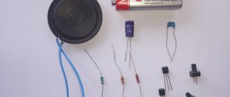
- set of speakers for a stereo system;
- ready-made mp3 player;
- ready-made radio receiver (it is advisable to choose a professional model);
- computer (or homemade) power supply;
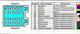
- a ready-made pre-amplifier with an equalizer (a device from any musical equipment is suitable, for example: an electric guitar, a DJ sampler, a mixer, etc.);
- radio components for the amplifier - according to the selected circuit;
- cooling radiators or fans for the amplifier;
- enamel wire for filters of multi-way speakers;
- network cable ShVVP (2*0.75 sq. mm.);
- non-flammable cable KSPV (KSSV, 4*0.5 or 2*0.5);
- 3.5-jack connectors for connecting speakers.
A passive speaker - usually a subwoofer - that can be easily disassembled and rebuilt, perhaps replacing the top, bottom and side walls with longer ones, is suitable as a finished enclosure. Refer to the drawing. It will be difficult to install an amplifier and power supply in the “satellites” (high-frequency speakers) - a radiator or cooling fans will take up a lot of space. If the center is small, use the housing and supporting structures from the car radio. For a self-made case you need:
- chipboard, MDF or natural wood (the latter option is most preferable - unlike MDF, where there are often voids);
- furniture corners - will make the structure easily disassembled;
- sealant or plasticine - eliminates cracks, making the structure impenetrable to the air pressure produced by the speaker;
- damping material for speakers – eliminates the resonance effect;
- epoxy glue or “Moment-1”;
- anti-mold impregnation, waterproof varnish and decorative paint;
- self-tapping screws, bolts and nuts, washers of suitable sizes;
- rosin, soldering flux and solder for a soldering iron.
Instead of paint, you can also use decorative film. Tools you will need:
- a classic installer's set (drill, grinder and screwdriver), a set of drills and a cutting disc for wood, a grinding disc for metal and a set of bits included;
- a mechanic's kit (hammer, pliers, side cutters, flat and figured screwdrivers, a hacksaw), you may also need hexagons of different sizes;
- To make sawing easier and faster, you will also need a jigsaw;
- soldering iron - it is advisable to use a device with a power of no more than 40 W; for the safety of the work being carried out, you will need a stand for it;
- sandpaper – needed in places where you can’t get to it with a grinder.
It is ideal if the home craftsman has a lathe. It will help to perfectly produce any rotating elements.
Step-by-step instruction
If you don’t have a ready-made case, start by making speakers. It is more convenient to make both cases at once.
- Mark and saw the board (according to the column drawing) for its future walls.
- Drill holes for the corners in the required places . If the board is smooth, use sandpaper or a sanding disc to clean the areas that will be glued.
- Mix up some epoxy glue and glue some of the speaker boards together or use corner pieces to join them together.
- A speaker that is active requires separate space for the power supply and amplifier . If the power is placed in the central block, cutting out the seventh wall for one of the speakers is not required. In this case, make a housing for the main unit according to a separate drawing - ideally, when its height and depth correspond to the dimensions of the speakers. This will give the entire stereo system a finished look.
- In the main unit, use partitions made of the same (or thinner) plywood to delimit compartments for the power supply, amplifier, radio, mp3 player and equalizer. The finished case from the radiogram undergoes the same modification. Assemble all the housings (speakers and main part) - without installing the front and top edges.
If you use ready-made electronic modules, all that remains is to place them in the right places.
- For volume controls, equalizer, USB port of mp3 player, radio module tuning knobs and stereo amplifier outputs (to speakers), drill and cut technological holes and slots in the front wall of the main body.
- Solder the mounting wire to the inputs and outputs of the electronic modules and label them.
- Place each of the electronic units in its own compartment . For the electronic module of the mp3 player and the power supply board, you will need rack-and-screw fasteners. In extreme cases, they will be replaced by long screws with additional nuts and engraving washers holding them. It is better to make the fastening heads on the outside (bottom, back) hidden so that they do not scratch the surfaces on which the center itself stands. It is advisable not to modify the receiver - it already has a stereo output, all that remains is to supply power to it.
- Align the technological slots and holes with control knobs , switches, etc.
- Connect all devices according to the block diagram.
To assemble the speakers, stick to the plan.
- Cut holes for the speakers in the front edges (along their radius). The speakers should fit into them freely.
- Solder the wires to the speaker terminals.
- If the column has two or more lanes, make separation filters . To do this, cut pieces of plastic pipe according to the drawing to the required length. Sand their ends with sandpaper. Cut out the sides for the coil frame, and also clean the places where they will be glued. Mix up some epoxy glue and glue the sides of the coils to the main part. You can replace epoxy glue with hot melt glue - it hardens in a few minutes. After the glue has hardened, wind the required number of turns of enamel wire onto these coils. The diameter and cross-section of the wire are also determined by the circuit diagram of the column. Assemble an isolation filter - the coils are connected to the capacitors according to a typical low-pass filter circuit.
- Connect the speakers to the assembled filters . Take out a common cable from each speaker by drilling a hole for it on the side (from the side of the main unit) or in the back. To prevent the cable from accidentally being pulled along by careless movement of the connection, tie it into a knot before passing it through the hole. For speakers with a power of more than 10 W, a SHVVP wire with a cross-section of 0.75 square meters may be required. mm.
- Connect the speakers in test mode to the newly assembled main unit of the music center.
Experience the sound quality the entire system produces. Additional debugging may be required.
- If wheezing, insufficient or excessive volume levels, or incomplete reproduction of low, mid and high frequencies are detected, equalizer adjustments and amplifier debugging will be required . Check the quality of radio reception from the radio receiver board - you may need an RF amplifier to cope with the unstable reception of radio stations. Check the operation of the mp3 player - it should play tracks clearly, the buttons should not stick.
- If radio reception is unclear, an additional antenna amplifier will be required. Radio amplifiers for cars are in greatest demand - they consume 12 V current. The amplifier is placed on the antenna input side.
- After making sure that the assembled music center works smoothly, insulate the remaining solder joints of wires and cables.
Close and finally assemble the speakers and main unit. The music center is ready for use.
Device testing
To test the music center, you must first load the audio file onto a portable storage device with a USB output. After this, turn on the music center to the mains voltage. An indicator should light up confirming that it is turned on.
Then insert the flash drive into the desired USB port. If all steps were performed correctly, the speakers should play sound. If there is no sound, turn up the volume or check the connections of all contacts.
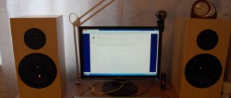
So, I didn’t make the whole body, I just used part of the table, but made something like a casing with cardboard and colored tape.
I installed an 80 mm fan from a computer power supply there and bought 2 car switches with bulbs of different colors.
One turns on the power supply to the fan, and the other turns on the backlight for the color music system, which I recently assembled.
The fan is connected through a simple transistor voltage regulator, which can be used to regulate the speed of rotation of the blades - after all, we don’t always need 100 percent of the revolutions. Its diagram is in the figure below:
The regulator is made as a canopy, directly on the variable resistor itself. I screwed a piece of aluminum onto the transistor just in case. Although it practically does not heat up.
Why did you use cardboard? It is good because it is perfectly cut and takes any necessary shape, the switches are of excellent steel, and cooling is ensured.
Power supply – switching, 12V 4A. Its power is quite enough to power the entire system.
And all this equipment is connected to a surge protector.
Total system costs:
Power supply 700 rubles - 12 volts 4 A - radio 900 rubles together with a power filter, casing and all wiring. - speakers - 2 sets of Mystery MJ103BX speakers 800 RUBLES each - 1600 rubles with my discount 1500 rubles - two switches with 12 volt indication – 45 rubles. - fan regulator and transistor, tape, electrical tape and other consumables were already in stock.
In your version, you can use textolite, aluminum or plywood for the body (placing the radio inside the old speaker). The main thing is that I showed you the very principle of constructing such devices. The design of the homemade music center has been installed and has been pleasing with its convenience and good performance for many days now! Comrade was with you. redmoon.
Discuss the article HOW TO MAKE A MUSIC CENTER
A music center can be built from an old cassette media center. With due diligence, you will get a functional and completely modern device. The process of creating a device with your own hands will require imagination, a set of tools and a little experience in working with electrical engineering.
You can create a homemade music center from an old car radio. Most of these devices have a powerful amplifier in the electrical circuit, which allows:
- Reproduce sound using suitable passive acoustics left over from an old tape recorder or player.
- Depending on the complexity of the device, play CDs, including in digital formats.
- Install a radio whose antenna can be mounted inside the speaker.
The photo shows an example of a homemade music center. In fact, this is the basis, which can then be brought to the desired level: create finishes, design the body, use computer modding tools.
Another way is to make a music center from an old player or tape recorder, using almost all the components of the donor device.
The radio can be disassembled and its electronic components can be placed inside the body of the old media center. Such work is not difficult: the design already contains an antenna and a power supply, which are often standardized and do not require modification.
You can place an old radio in place of cassette decks
not used due to outdated storage media.
For the above options, the power source can also literally be “lying under your feet.” Worn out, unusable due to a drop in power or slight deviations in parameters, computer power supplies are an ideal option.
The comb, which attaches to the motherboard, contains pins for system startup and a low-power, fixed-voltage bus. To connect to a 220V network, the computer unit has enough four-pin connectors.
Sometimes time is so inexorable...
Players and tape recorders are becoming a thing of the past.
Cassettes, vinyl records and tape reels, if not thrown away, have long been gathering dust on the shelves, as a tribute to the memory of our “audio-loving” youth. Today, even CD and DVD players have gradually begun to be replaced by storing music and video data on the computer's hard drive. The world is changing, progress is gradually “taking its toll” despite the efforts of individual fans who still listen to music on old equipment. Well, this also has its own enchanting magic, which lies not only in the delights of analog sound, but also in the very “sacred act” of installing a record on a rotating disk of a player, or charging a tape through the guides of a reel-to-reel tape recorder, which was popularly called a “reeler” . But be that as it may, most of us have completely switched to the “digital” media data format, which completely saves us from fussing with tape and vinyl, while providing high quality sound.
Of course, heated and ongoing debates about what is better - analogue or digital audio will most likely continue as long as these formats exist, but they are unlikely to be of interest to the average person, since the use of digital format in audio and video playback has undeniable advantages:
- Convenient data storage;
- Convenience of quick access to data;
- Almost instant selection of tracks to play;
- Minimum copying time without loss of quality and regardless of playback paths;
- Significant savings on media, since old media - cassettes and reels are practically no longer produced by modern industry, and it is becoming more and more difficult to find new ones (and the prices for such things are gradually rising).
All this inexorably leads us to the fact that a modern media center must be fundamentally different from the set of sound equipment that was used in past years, but the most important thing is that even a novice digital technology user can assemble a media center with his own hands .
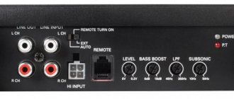
Electrical connection diagram
Although most radio tape recorders have a different number of outputs and inputs, it is not difficult to find a method for connecting them to a 220 Volt network when making a home audio system. The standard electrical diagram for connecting cables looks like this:
To power the system, a regular power supply from an old PC is used. Before connecting it to the system, you need to check that the device has enough power to receive 5 amps.
Required connectors for connection:
ATX type power supplies must be connected via control connectors. They are on a 24-pin comb.
The image shows which wires need to be connected to the car radio.
The back of the device looks like this:
For different types of radios, the location of the power supply, the number of sound outputs and other parameters may differ. Only the color designations of the cables do not change.
Non-standard paths
Home craftsmen who do not have such a ready-made solution as a car radio can safely use their imagination. There are a lot of options:
- The power supply can be a computer power supply or a switching power supply suitable for power and voltage: from household appliances, mobile phones.
- Computer drives with audio output are suitable. Such a device is usually equipped with a start button, which also serves to go to the next track; double-clicking it stops it. Some older drives, such as the Creative brand, are equipped with a full set of control keys, as well as a volume control on the front panel.
- Do you want to listen to the radio? A small radio the size of a matchbox, receiving a signal from a retractable antenna, will sound perfectly high quality.
- There are no problems with digital formats either. An inexpensive FM transmitter paired with the already mentioned tiny receiver is an ideal tool for obtaining high-quality sound.
- For the truly lazy, there is an ideal donor - an old but working electronic alarm clock. Chinese models easily act as radios and read digital formats from memory cards.
You won't have to do much to fit all of these devices into your old media center. The devices need to be freed from their cases, maybe a little work with a soldering iron to bring the control buttons, slots for memory cards and USB to the front plastic panel of the center. The answer to the question of how to make a power supply circuit becomes clear if you count the number of outputs in a computer power source - there are enough of them for everyone.
What are embedded audio modules
To quickly modernize an old music center, you should use a special built-in audio module - sound converter. You can make such a device yourself, but making a homemade module will require a significant investment of time and special knowledge in the field of electrical engineering and electronics. It is much easier to buy finished products
, presented in a wide range by Chinese manufacturers.
Purchased audio modules have a digital-to-analog conversion
. Some models are additionally equipped with mini sound amplifiers. More expensive devices are equipped with an LCD display, Bluetooth, remote control and additional connectors.
Advice! For home improvements, you can limit yourself to the simplest product with one USB connector.
In terms of their functionality, the modules are similar to a compact mp3 player
, which does not have its own power supply and speakers. It is to fill these missing devices that the old audio system will be used.
To remodel, you will need a music center that is still functional.
the following nodes:
- battery pack;
- speakers;
- sound amplifier.
Instructions for creating a music center from a car radio
You need a power supply to create a music center. But it doesn't have to be new. If you have an old computer, unplug it and use it for your project.
- To get started with your home stereo system, locate the green and black wires on the block and place a piece of wire between them to act as a jumper wire.
- On the car stereo, twist the red and yellow cables together.
- Next, connect the black ground wire on the stereo to the black wire on the connector.
- The red and yellow wires of the stereo connect to the yellow wire of the connector.
- Then follow the usual instructions to connect the stereo to your speakers.
While using a power supply to power your car stereo in your home is one way, you can do it even if you don't have a unit.
- You can connect the speakers to the radio using the gray and green wires.
- You may need to use an additional speaker cable.
- The next step is to connect the yellow and red wires on the stereo and add an additional speaker for stereo sound.
- Connect the wires with soldering or electrical tape to get a quality result.
- You need a 12V power cord to connect the device to the network. You can easily purchase it at any technical store.
- Cut the end of the power cord and connect the black wire to a line of white around the red and yellow stereo wires.
Connect via computer power supply
Any computer power supply produces +12 V and at least 10 amperes in this circuit. This is the voltage that needs to be supplied for the car radio. The first thing to do is start the power supply. In order for it to work when plugged into the network, you need to short-circuit the black and green leads. They are output to the power supply connector for 4 or 24 outputs. They must be connected with a jumper. Or cut off the necessary wires, strip the insulation, twist them together and insulate them.
Stages of work, wires and pads
When the power supply is turned on, the fan should start working.
Where to get 12 V on the computer power supply
We take the power supply connectors and look for the yellow wire. Usually there is a large connector and several small ones. The “large connector” can have 12 or 24 outputs. Depends on the block model. But the yellow wire is still there.
Where to look for 12 V on a computer power supply
The small connectors that go to peripheral devices also have a yellow wire and 12 V. You can take the power from there.
This is what a computer power supply looks like
You can make sure that it is working correctly by taking a multimeter and measuring the voltage on the yellow wire. On the multimeter we set the DC voltage measurement to 20 volts.
The stripped wire can be inserted into the block. But it’s better to cut off the wire, strip it and connect it to the desired conductor from the radio.
The second black wire we need is negative.
All this work - removing, cleaning, connecting - is carried out with the power supply unplugged.
How to connect wires
On the radio, power is supplied to the red and yellow wires. If you have a connector, you must either insert the wires into the appropriate sockets, or cut off the block and strip the necessary wires. If you decide to cut off the block, twist the wires that supply power to the car radio together. And we connect them to the yellow wire from the computer power supply.
We connect the black wire of the radio to the black wire from the power supply.
After turning on the power and connecting the speakers, you can enjoy music at home, in the garage or in the country house
If the block has not been cut off, you need to install a jumper between the red and yellow wires (you can use a piece of wire with stripped ends). Plug the yellow wire from the power supply into one of the connectors with a jumper. So it turns out that power is supplied to both inputs at once.
Selecting a car radio
Since by default, to create a homemade one, we will use a device lying around idle, any car radio will suit us. But this “any” should still have a minimum set of functions:
- At least two-channel output with a power of 40 W each;
- Tuner;
- CD/DVD/MP3 disc player;
- USB – connector for reading information from flash drives.
In addition, you should pay attention to the sound card of the device itself. Some radios can even surpass most modern music centers in terms of purity and sound quality. And although, due to the fact that the car radio does not have large and capacitive capacitors in its “arsenal”, due to which it loses in the reproduction of low frequencies to powerful stationary speaker systems, it is definitely at its best in the reproduction of the high-frequency range
Another definite advantage of the car radio is the presence of a multi-stage frequency-separated equalizer, while most stationary music centers are equipped with only standard presets
And although, due to the fact that the car radio does not have large and capacitive capacitors in its “arsenal”, due to which it loses in the reproduction of low frequencies to powerful stationary acoustic systems, it is definitely at its best in the reproduction of the high-frequency range. Another definite advantage of the car radio is the presence of a multi-stage frequency-separate equalizer, while most stationary music centers are equipped with only standard presets.
Useful tips
When soldering active radio components (diodes, transistors, microcircuits), do not hold the soldering iron at one point for too long. Semiconductor radio components suffer thermal breakdown when overheated. Overheating also peels off the copper foil from the dielectric substrate (base made of fiberglass or getinax).
An mp3 player is placed in a car radio instead of a cassette deck or AudioCD/MP3/DVD drive - space allows.
In the absence of a standard receiver, the ideal solution would be to externally connect Tecsun or Degen radio receivers - they provide reception at a distance of up to 100 km from FM repeaters. The high quality of stereo sound in the headphones speaks for itself.
How to make your own sound amplifier for a radio on a chip
Some older car radios do not have such useful inputs as USB and AUX, so to use them as an amplifier you will have to remove the device from its seat and open the printed circuit board. If you have no experience working with electronic circuits, then you should not take on this work. First, you need to find a low-frequency amplifier integrated circuit on the car radio board. This is a large part and the only one that is installed on the heat sink. On the circuit diagram and on the board it may be designated AMP or POWER AMP. Next you need to determine the input pins of the amplifier. There are two of them on the chip - the left channel input and the right channel input. The left channel can be designated Line L or L-in, and the right channel – Line R or R-in. You can determine correctness by touching each contact with your finger. A hum will be heard from the corresponding speakers. In this case, the power of the car radio must be turned on. The ground or common wire is marked with Line GND.
If there are no markings on the diagram, you can find the channel inputs directly on the chip. To do this, you need to sequentially touch all the terminals, focusing on the appearance of hum in the speakers. You cannot solder the connector to these contacts. It is necessary to determine the connection points for the coupling capacitors and solder the wires to them.
The wiring of channels on the plug and socket must be done using shielded wire according to the following diagram.
A homemade sound amplifier from a radio can be used with any external sound source. There are no tone controls in this design, since the signal is fed directly to the input of the final amplifier, bypassing the equalizer. In order to reduce the noise level, you should cut off the tracks going to capacitors C1 and C2 from the pre-amplifier of the playback head.
If your car has a new radio, you can make a compact audio amplifier from the old one. To assemble a sound amplifier from a radio, you need to remove everything superfluous and unnecessary.
How to assemble a sound amplifier from a radio can be understood from the figure. The ZXM8330-PA car radio is assembled on two microcircuits and three transistors. The FM tuner is assembled on a TA2003 chip, and the final amplifier is built on a TDA2003 chip. The radio receiving part and the first transistor in the stage of pre-amplification of the signal from the magnetic head can be immediately eliminated. The power supply wire to the electric motor also needs to be cut. The printed track of the tuner power supply, coming from the “Radio” - “Tape” switch, and the track from the output of the microcircuit to the collector of the second transistor are also cut. You can experiment with the remaining elements of the circuit. If the external device that will be connected to the amplifier has a sufficiently powerful output signal, then it should be connected to the upper terminal of the variable resistor “VOLUME” in the circuit.
To supply a weak signal, you can use the collector of the second transistor, that is, the point where the signal was supplied from the tuner. In this case, the tone controls and the volume limit switch “Mute” will work. The power supply circuit of the first and second transistors must be broken. In a car, all electronics are powered by a battery. If the amplifier is to be used as a standalone device, it will require a simple 12-18 V power supply. The amplifier provides an output power of 6 W on a 4 ohm speaker and 10 W on a two ohm speaker. The maximum current consumption is 3.5 A. Using a similar principle, you can make an amplifier with your own hands from any car radio. The main thing is to correctly identify the input circuits and disconnect from the input all unnecessary stages that may be sources of noise. This is especially true for the amplification stages of the playback path. Working with stereo systems is a little more complicated, but the technique remains the same.
Making a home audio system - part 1
Hi all!
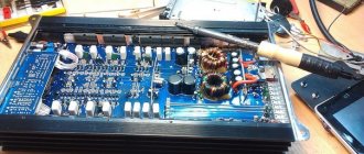
I finally got photos of the amplifier) But there are no photos of the unit and its insides yet, but that’s for the best, I’ll make a separate post on power supplies, there will be more useful information than in one post about the audio system =) Let’s return to our systems. Initially, the idea was to make something compact and extremely functional to replace the old Amphiton amplifier, which could not withstand the potentiometer’s maintenance and died irrevocably. Well, that's for the best.
Now, in the era of the general availability of various sets and kits in various online stores, there were actually no questions about what to take as a basis) After a little rummaging through a well-known resource, I selected the appropriate elements.
The basis for a lot of functionality was a car radio. Bonuses include support for bluetooth (there are also models without it, which are cheaper), radio, flash drives and memory cards. And of course a linear input.
The tape recorder is quite good, but it definitely needs to be improved, because in its original form it does not work well.
I settled on this option. There are also others, but with the same functionality.
As a power amplifier, I used a ready-made TDA7492 chip with an output power of 2x50 watts. This is enough for a home, but if you want to get more power, then you can take a 2x100 watt amplifier, which is quite a bit more expensive. When choosing an amplifier, you should pay attention to what kind of power it requires; for ease of manufacturing the power supply, it is best to take amplifiers with single-supply power, as I actually did.
The body of the device can be made from any material that you find at hand, the main thing is that it is of sufficient strength. I chose plywood, which was used for laser cutting and engraving. If you also want to repeat it from plywood, look for advertisers in your city; they often have the necessary equipment.
Among the features of the amplifier is the ability to immediately connect two pairs of speakers. Here they are connected in pairs of 1 or 2 pairs, and medium mode, when the speakers are disconnected from the amplifier.
I also installed a fuse and a toggle switch on the amplifier if another power supply is connected instead of the standard one.
As I said, the radio has problems. In particular, this is a squeak when bluetooth is working. Poking around on Google led to the advice to disconnect the analog and digital grounds on the board. I also added an additional filter to the preamp power supply. In the photo of the board you can see rosin; there was a jumper in this place.
Through such simple manipulations, Bluetooth is completely cured of unpleasant sounds and works very cleanly. I will also say that I placed a volume knob between the radio and the amplifier so that I could control the volume without using the remote control.
Here are some more brief characteristics of the device.
If you remove all the design frills, in the form of a laser-cut body, then the price tag of the device will be affordable, while with minimal modifications the sound is of decent quality and is quite suitable for the home.
Also, in the near future I will make a big post about power supplies that can be used with this or another device in order to fully cover this topic.
If you have any questions about the circuit or assembly of the device, please contact my group -
Creating a home speaker system
So, the essence of the issue is clear to us. A car radio with speakers (see How to choose speakers for a car radio on your own) have been lying nearby on the table for a long time and are “asking for battle.” Now we are the only ones who don’t understand how we can “connect” 12-volt equipment with a 220-volt alternating network? I must tell you that this problem has several solutions, which are contained in the instructions below on how to connect a car radio from a 220 network.
Method one: connection via a homemade step-down transformer
This method is the most complex and time-consuming
Although the level of modern electronic technology allows us to completely abandon it, due to the fact that we are considering all the ways on how to connect car radios to 220 V, we will still pay due attention to it
Preparation
So, before connecting the car radio to the 220 network, we will have to create a transformer that steps down to 12 volts with our own hands. Why do we need:
- A similar (see photo) transformer that converts the standard network voltage to a lower one (in our case, 36 volts);
- Insulating material;
- Wire of suitable cross-section and length;
- Multimeter/voltmeter;
- A calculator, although the calculations are not at all complicated, you can get by with a piece of paper and a pen.
Step-down transformer 220/36 Volt
Creation
In order to make the task as easy as possible and not disassemble the transformer winding itself, we use the free space of the magnetic core area. We wrap the free area of the magnetic circuit with insulating material and wind a piece of the wire of our choice onto it of any length. Let's say we got seven turns. In order to calculate the number of turns and wire length required to reduce the voltage, we need to perform the following procedures:
We assemble a circuit for switching on a transformer using a piece of wire wound around a magnetic conductor and measure the output voltage;
We take readings from seven turns of wire
- The multimeter gave a value of 2.9 volts. This means that we have 0.41 volts per turn of the secondary winding. From this ratio we obtain the number of turns required for an output of 12 volts: divide 12 by 0.41 and get 30 turns;
- We measure the length of the wire spent on the experimental seven turns, we get 126 centimeters. That is, there are 18 centimeters per turn (126 divided by 7), which means that for 30 turns we will need 540 centimeters of wire.
- Next, we wind this whole “thing” onto a magnetic circuit, assemble the circuit and check our calculations with a multimeter.
Center of the home universe
The general connection diagram for all devices inside a universal home center will look like this:
Most likely, most of us have already heard and watched enough commercials about the “wonderful” SMART functions of modern television receivers, and many have even tried the new product for a taste. Liked? Most likely no. Why? There are several reasons:
- TV receivers are still quite slow , since manufacturers, for a number of technological and economic reasons, are in no hurry to install fast processors on them. Therefore, using the Internet or network resources from such a device is not yet entirely comfortable.
- Technical capabilities are several times inferior to the level of even an entry-level home PC.
- Some companies release their SMART TVs with an ill-conceived and confusing interface that can only be understood by a very experienced user or a person knowledgeable in this technology.
- Incompatible with a number of existing media file formats.
Because of this number of shortcomings, a television receiver with the SMART-TV function is just another marketing ploy by manufacturers of such equipment, and is not yet capable of becoming a full-fledged media center. At the same time, it has one very necessary function that will allow it to be used as one of the components - a large screen with FullHD resolution.
The following devices can be successfully used as the basis of the “control center” for playing media content:
- A personal computer with a Windows or Linux operating system.
- A laptop or netbook with a Windows or Linux operating system.
- Tablet based on Android or Windows 8 OS.
- TV set-top box (mini-computer) running Android OS.
POWERFUL AMPLIFIER FOR BEGINNERS
I highly recommend that beginners assemble this circuit. I am not a master myself, but rather a beginner radio amateur. Well, I already know the basics of electronics, basic things, so I decided to try my hand at this design... It all started with the fact that I had long wanted to build myself an inexpensive, but quite powerful sound amplifier. Not on the simplest 1555, which play no better than ordinary mini-speakers, but at least by fifty watts. Well, I've reached my goal. I assembled an amplifier using the well-known TDA7294 microcircuit. You can easily squeeze out 100 W or more from it. I bought the microcircuit for only $1.5, and took everything else from a Soviet TV, I found almost everything there.
Microcircuit connection diagram
The advantage of this amplifier is that it is so tested and retested by thousands of radio amateurs that all beginners can assemble this circuit without any problems - there are no serious obstacles here. All parts can be found at home (except for the chip itself).
It is permissible to take the TS-160 power transformer from the same TV, disassemble it, leave the primary, and wind the secondary with 172 turns of wire with a diameter of 1.5 mm. Low-power transformers are not suitable here (after all, you need 200 watts just for sound). The minimum power of the transformer must be over 100 watts if the microcircuit is powered by reduced voltage. It is known that the power supply of the 7294 microcircuit is bipolar. The voltage was -+ 55 volts. Current 2-3 Amperes. To be honest, I didn’t measure the current consumption, that is, I forgot. I remembered when everything was soldered. The power wires need to be thicker. At high volume, thin wires heat up and stick to each other, which actually causes a short circuit.
The diode bridge was taken from an imported TV, although the diodes got noticeably hot when playing sound. All other details were obtained from Soviet TV.
One more thing, the amplifier is equipped with a cooler, since the radiator was not very large. I assembled the diagram on a piece of cardboard. I didn’t find any textolite at all. For many radio amateurs, such luxuries as textolite, vitriol, and a laser printer are not available. I’m also on this list :( But you can see that if you want to do something, you can get by with little.
The parts were connected with copper wires. I didn’t install LEDs or other indicators at all, since seriousness and performance are important to me in the first place. The speaker is currently 20-30 W, 8 Ohm. I haven't bought the 100 watt head yet.
Photo of the finished amplifier is above. Yes, accuracy is not in the best condition. But surprisingly, everything turned out very well - there are no audible distortions. The input signal was supplied from the telephone. The amplifier started up the first time it was turned on and that made me very happy! With uv. best.boy99 UMZCH Forum
Music center on FM modulator
Today, motorists are offered an interesting feature: listening to flash media through the car’s receiver. A key fob is used where the memory device is connected. Then the FM modulator works like a walkie-talkie. Emits radio waves that the car's receiver can pick up. Both devices are tuned to an arbitrary FM frequency, and nearby listeners (receiver owners) enjoy the content from the flash drive.
The invention is based on the fact that the transmission power is low. However, it is sufficient for the components of the music center to work in harmony. An FM modulator is used to create autonomous systems. If you assemble a music center and include a receiver (any old Soviet one), you can listen to flash drives on decent speakers, even in a car. The gadget is powered by a cigarette lighter; the battery is suitable as a source, just like a computer power supply.
It is possible to make a music center yourself, as indicated, if you have already purchased an FM modulator. There is no need to add an amplifier; the receiver has a built-in one. But for working with large speakers, an extra cascade will not hurt.
Don't forget that speakers are loaded with electronics for good reason: radio equipment does not like vibrations, especially powerful low frequencies. For this reason, collecting electronic components in one box is not a good idea. It’s ideal to plug a couple of speakers from an old tape recorder into the box. We believe that loudspeakers are designed to coexist with electronics without causing mutual harm.
An FM modulator can be purchased for about 300 rubles. If you have an old receiver and can assemble a low-frequency amplifier, be sure to try it. Any Tourist will do. If a station appears on the working channel of the FM modulator, you just need to rebuild it and the receiver. This is not very convenient when constantly changing broadcast zones.
What to do if you want to do everything from scratch
If you want to mount everything in a unique housing or use old passive acoustics for this purpose, you will definitely need a power amplifier. If there is an old one lying around somewhere, the issue can be considered resolved. Those who don’t have anything suitable at hand will have to improvise a little. The ideal place where you can find everything is the well-known AliExpress. Here you will find both integrated circuits that are inexpensive and can provide high output power per channel, as well as standard products that can be adapted to solve the task at hand - creating a music center.
Hello to all DIYers! A friend recently gave away a burnt-out car radio that he bought in a hypermarket with working USB and FM. Connected it to power and it worked. I disassembled it further, a piece of plastic was knocked out on the output microcircuit - everything is clear, the outputs are short-circuited. I decided to restore it, fortunately I had three free days, and I recently assembled an amplifier based on the TA8205.
I bit out the output microcircuit, soldered the power supply, inserted the flash drive and started checking the signal with a probe. I found the left and right sound channels. I connected it to the TA8205 and almost went deaf from the distortion and 50 Hz background. 3 hours of tambourines and dancing and a solution was found. There is a 30 kilo-ohm resistor at the input. But I still couldn’t figure out the power supply; I had to install a small 12-volt transformer and a stabilizer on the Krenka for the radio.
The sound turned out to be more or less decent and powerful, perfect for a garage. I decided to tinker with the case, then in the garage I found a plastic speaker that matched the size of the front panel of the radio, and sawed more than half of the case with a grinder. I cut out a window for the panel, a radiator, a switch, terminals for the speakers, and cleaned it with a file. The transformer for the amplifier was installed from the center and is switched on via a relay from the signal from the radio itself. I fastened everything together with bolts and with hot glue.
Well, in addition, I decided to adapt output power indicators on LM3915 into the case, fortunately I had 2 pieces in my stash and recently bought 500 pieces of 3 mm from the Chinese. LEDs for 250 rubles. I drew 2 scarves for microcircuits and LEDs with a marker, the printer ran out of toner. I soldered the whole thing, connected it, and it works. It turned out to be quite good, a la music center. The photographs show the entire assembly process.
Connecting the car radio to the 220 network
Surely every car enthusiast has come up with the idea of using a car radio, in addition to the interior of the car, whether in the garage, in the country, or even in the space of his room. Well, why not? After all, even the most standard car radio, the price of which is not comparable to the price of a music center, has normal output data and not the most famous home speakers without loss in sound reproduction quality. And if, in addition, the car radio has a multi-channel output, then by connecting all the provided acoustics to it, we end up with an almost complete home theater, assembled with our own hands.
We connect the car radio at home, with our own hands
If you are a car enthusiast, then probably at least once in your life the thought of trying to connect a car radio to your computer at home flashed through your head. Indeed, if you have a radio, why not try it? Sometimes even the most ordinary radio from the middle price category can surpass the speaker system of the most famous manufacturer for a couple of thousand dollars. Many car owners very often replace their radios with new ones, but the old ones can still serve you. They can be connected not only at home, but also in the country house and in the garage. They will serve as a speaker system or home theater. You can make a truly excellent home theater with your own hands. But how to do this and connect the radio at home to the power supply?
Music center on FM modulator
Today, motorists are offered an interesting feature: listening to flash media through the car’s receiver. A key fob is used where the memory device is connected. Then the FM modulator works like a walkie-talkie. Emits radio waves that the car's receiver can pick up. Both devices are tuned to an arbitrary FM frequency, and nearby listeners (receiver owners) enjoy the content from the flash drive.
The invention is based on the fact that the transmission power is low. However, it is sufficient for the components of the music center to work in harmony. An FM modulator is used to create autonomous systems. If you assemble a music center and include a receiver (any old Soviet one), you can listen to flash drives on decent speakers, even in a car. The gadget is powered by a cigarette lighter; the battery is suitable as a source, just like a computer power supply.
It is possible to make a music center yourself, as indicated, if you have already purchased an FM modulator. There is no need to add an amplifier; the receiver has a built-in one. But for working with large speakers, an extra cascade will not hurt.
Don't forget that speakers are loaded with electronics for good reason: radio equipment does not like vibrations, especially powerful low frequencies. For this reason, collecting electronic components in one box is not a good idea. It’s ideal to plug a couple of speakers from an old tape recorder into the box. We believe that loudspeakers are designed to coexist with electronics without causing mutual harm.
An FM modulator can be purchased for about 300 rubles. If you have an old receiver and can assemble a low-frequency amplifier, be sure to try it. Any Tourist will do. If a station appears on the working channel of the FM modulator, you just need to rebuild it and the receiver. This is not very convenient when constantly changing broadcast zones.