If you have such symptoms, we advise you to find a diagram of your plug and re-solder the connector, especially since using these instructions you can do this yourself even without much soldering experience.
So, a TRS type connector is intended for connecting devices, for example, headphones and a player, with each other. The device consists of a plug (plug) and a socket (jack). Often this connector simply breaks at the point where the wires enter the connector itself. Because of this, either the right or left earphone or both at once may not work for you. Moreover, sometimes extraneous noise appears due to wire breaks in the jack 3.5 connector itself.
In general, it is worth noting that the abbreviation TRS itself comes from the English words: tip (tip), ring (ring) and sleeve (sleeve). Among the Russian-speaking population, the concept has been established that “jacks” are the plug itself, so if you use the original name of the TRS connector in everyday life, many will not understand what we are talking about.
Universal plug - 3.5 jack pinout for connecting to headphone and smartphone jacks
Pinout of jack 3.5 is not particularly difficult; skill with a soldering iron is enough. Therefore, almost any user of headsets that require such a connector can repair a failed connector or solder a new one to the wire.
Audio jacks were invented in the 19th century for use in telephone switches and are still widely used to transmit analog audio signals.
Contact configuration
| Pin no. | PIN name | Description |
| 1. | Tip | Left |
| 2. | Ring | Right |
| 3. | Ring | Earth |
| 4. | Sleeve | Microphone |
Short description
The 3.5mm jack is a universal audio jack size for smartphones, PCs and laptops. Additionally, for hams, the 3.5mm audio jack is a useful component for projects that connect to headphone jacks. There are different types of audio connectors such as TS, TRS and TRRS used in various applications, but the most common ones that we see in everyday life are TRS and TRRS.
Self-pinout of 3.5 mm jack
To use the 3.5mm audio jack in your projects or prototypes, you must solder wires to the jack pins. Remove the above plastic shell and you will see the connector pins as shown in the images above. Now use the stranded wires to solder the pins and then cover it with the plastic casing again.
Pinout 3 5 mm jack 4 pins
We melt
We brazenly and unceremoniously melt the edge of a piece of pipe to the connector:
All photographs presented in this article are the first attempt to use this method. Everything was invented on the fly.
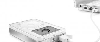
It was decided that if we were to do it, we should make an L-shaped connector, which would be less susceptible to jeans being killed by pockets.
How to Determine Headphone Jack Size
Most users can determine the diameter of a connector or plug visually, since the vast majority of devices are equipped with a 3.5 mm jack. If the diameter of the plug in your device is smaller than usual, then it is a 2.5 mm jack; if you are using professional equipment or a musical instrument with a connector of increased diameter, it is probably a 6.35 mm connector. It will not be difficult to distinguish a jack from Lightning and US.
Inexperienced users should use a measuring device, such as a caliper, although a school ruler will show a difference of 1 mm.
Plug types and applications
Depending on the diameter of the working surface, connectors are divided into:
- Micro jack 2.5 mm . They are equipped with small portable devices such as phones, players, etc.
- Mini jack 3.5 . They are installed in household appliances: computers, TVs, etc. In addition, the pinout of jack 3.5 is extremely simple.
- Big jack 6.35 . Mainly used in professional equipment: electric musical instruments, powerful acoustic amplifiers, but can be built into budget equipment, such as karaoke microphones, metal detectors.
Based on the number of outputs (pin), jacks are divided into:
- Two-pin ( TS ). They transmit an asymmetrical signal, for example, a mono signal is sent to headphones or audio is recorded using a microphone.
- Three-pin ( TRS ). Using them, you can transmit both an asymmetrical signal, with pins 2 and 3 connected by a jumper, and a symmetrical one.
- Four-pin ( TRRS ). They can immediately transmit video and audio information. Modern phones, tablets, video players, etc. are mainly equipped with four-pin connectors.
- Five-position ( TRRRS ). An uncommon connector used by Sony in the Xperia Z smartphone for the simultaneous operation of two microphones, one of which works for noise reduction. TRRS compatible.
There are also two types of sockets: regular, created for a specific type of plug, and with a switch - when the pin is inserted, the device switches from one position to another.
Very often there are situations when Chinese collapsible plugs, which were installed instead of a monolithic broken “jack,” do not completely fit into the sleeve or are poorly fixed. Such situations are possible when the diameters of the sleeve and plug do not match. Therefore, when choosing such a plug, it is advisable for you to check its outer diameter with a caliper along the entire working length.
How the headphone jack works
The pinout of the headphone jack (using TRS as an example) is a mirror of the pinout of the plug (the diagram is shown below).
For the connector with a TRRS microphone (used for a headset), the pinout is as follows.
Headphone circuit with microphone
For a headset, the schematic drawing looks different, because it is designed differently - equipped with an additional cable for transmitting sound from a microphone.
Have you noticed that in the diagrams there are different contacts for ground and microphone? Nothing strange. There are a couple of TRRS types (specifications) available with different ground and microphone contact locations. In CTIA (computer standard), the second ring (third contact) is connected to the common contact, and the sleeve is connected to the microphone, in the case of OMTP (telephone specification) it is the other way around: the 3rd contact is the speaker, the 4th is ground.
The standards are relevant only for headsets - headphones with a microphone; they have no relation to devices without one.
The standards are relevant only for headsets - headphones with a microphone; they have no relation to devices without one.
Figure No. 1
We noticed that some headsets with iPhone work adequately. The microphone fails, the volume control and track switching do not function due to the fact that most accessories are produced with the international OMPT pinout, and Apple uses the American circuit - CTIA. The problem is solved by purchasing a CTIA - OMPT adapter (see Figure No. 1) or by resoldering the 3rd and 4th contacts (they are swapped) in the headset.
The headphone pinout will allow you to correctly solder the pins when repairing the device, for example, replacing a damaged plug or cable. It depends on the number of contacts and the specification used: CTIA or OMPT.
So, let's go fix the headset jack
First, let's look at the headset jack itself. It's called 4-pin Jack 3.5mm , but somehow it doesn't make any difference. So, it has 4 contacts, and each contact has its own purpose. There are two standards for pin layout:
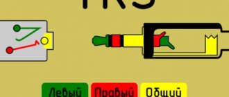
In this piece of art I tried to depict the purpose of the pins. M- and M+ are microphone contacts. The other three are the headphone contacts already familiar to you from the first article : G - ground, R - right, L - left. The colors with which the contacts are painted are not random; these are standard colors that are most often used by manufacturers to distinguish wires.
Now the first option has almost completely died out. And this is not due to the fact that the second traffic lights on the contacts are more correct and not even with the Rastafarian tricolor, but with problems of compatibility with 3-pin connectors of laptops, players... I think everyone has come across headphones that play normally from a laptop only when they are not inserted all the way. This is the first option.
But let's return to the colors of the headset wiring. In order not to be unfounded, here is a cut cable from a Beats Tour headset. Classic wire color scheme:
But alas, everything is not always so good and the manufacturer does not always make our life so easy. It is not possible to consider absolutely all color scheme options. And it doesn’t make sense, it’s better to understand how to determine which wiring is responsible for what in any circuit. This is what we will do
Pinout of the wire of the 3.5 connector (Jack) with and without a microphone.
Nowadays, the pinout of headphone wires with a microphone shown in the first picture below is generally used everywhere, but there is also another one, which is mainly used on old phones and in phones from some manufacturers. They differ in that the microphone and ground contacts are swapped.
If you have resoldered the headphone plug and you have a quiet sound in the headphones, and when you press the headphone call button the volume in the headphones increases, then you should resolder the ground and microphone wires (swap them).
Headphone circuit
Electrical diagram of three-pin headphones.
Jack connector wiring diagram (sectional view).
In most high-quality headphones, the conductors leading to the headphones are made of shielded cable. It consists of a central insulated core and a screen in the form of a braided cable.
Recommendations: How to solder a headphone plug
, How to disassemble headphones: instructions with step-by-step photos of repairing all elements of the headset
, Headphone wiring
The central core can be additionally made of varnish insulation, with silk thread woven in for greater resistance to fracture and stretching. The process of soldering such conductors in case of damage is technologically complex; it is necessary to have skills, special flux and low-melting solder.
The three-pin headphone jack has the international TRS classification. The definition of the abbreviation is clear from the figure below.
If the headphone connector is broken, or the conductors in it are broken, you can replace the connector with a new one. Standard headphone connectors are usually non-separable.
It is necessary to purchase a dismountable connector, check that the color of the conductor matches the connection diagram and, using a soldering iron, solder, flux and a knife, first tin the wires, then the contacts for connecting to the connector, and then perform the desoldering.
Wiring is carried out in accordance with the installation diagram.
The four-pin connector is TRRS classified.
The pinout of TRRS connectors can be made in two versions: CTIA and OMTP.
Four-pin headphones usually have a microphone and a button. Pinout diagram for four-pin CTIA connector.
Pressing the button blocks the microphone.
When purchasing headphones with a four-pin connector for your mobile device, you need to determine what type of connector is needed. As can be seen from the pinout shown in the figure, the “common” and “microphone” pins are “confused” in these types.
The same brands of phones, but made in Chinese, may have headphones with OMTP pinout. If you connect the wrong pinout, the sound in the headphones will be distorted and the microphone may be damaged. In this case, it is necessary to resolder the connector contacts in accordance with the diagram.
Adapters from one standard to another are available for sale.
How to check pinout on a non-standard connector
For some time, mobile phones with non-standard (original) plugs went on sale. In this case, the headphone pinout has different connection schemes.
If it breaks, the cable is cut off and another headset is purchased. Then installation is carried out according to the pinout diagram.
Headphone pinouts are sometimes carried out without the help of a specialist, using the following steps:
- using an active solvent, disassemble the system housing;
- Next comes the ringing of the speaker terminals, taking into account that the common wire is zero resistance;
- ringing of connector contacts with zero resistance;
- determination of the connection contact (its number at which the multimeter** shows resistance close to zero) of the common wire;
- dialing to opposite speaker contacts;
- in the case of devices that have a microphone, look for connections to the connector pins for all pins.
* TRS is an abbreviation formed by Tip-Ring-Sleeve, which means tip-ring-sleeve.
** A multimeter is an electrical measuring device that includes the functions of an ammeter, voltmeter and ohmmeter.
What is needed for desoldering
To pin out a faulty headset, you must prepare the following:
- New connector for replacement. It should be the same type as the old one.
- For high-quality soldering you need a soldering iron. Its power should not be high - 25 watts.
- Rosin and solder.
Today, there are ways to connect a cable without resorting to soldering elements. However, the procedure carried out using a soldering iron guarantees better quality work. Soldered contacts are more durable and will last a long time.
Soldering jack and minijack 3.5
Headphone plug repair (with microphone)
Repairing a plug (soldering a 3.5 mm jack) is not that difficult. It is enough to have a normal soldering iron, more or less straight hands and a minimum amount of knowledge. It is precisely these (instructions for repairing the jack) that we offer, as they say, to your attention.
- Determine the location and type of breakdown (wire fracture in the plug area).
- Determine the number of pins (contacts) in the plug.
- Disassemble the plug (remove the metal part of the plug from the housing).
- Clean and tin the cut wire with a soldering iron.
- Determine the wiring.
- Solder the wire strands onto the stripped contacts of the plug.
- Fasten the braided wire to the “tail” of the plug (the place where the contacts are located).
- Put on the heat shrink tube and “shrink” it with a heat source.
Below we will look at everything in more detail. There is also a useful and visual video.
Preparing for work
To repair headphones yourself, we will need:
- non-conductive glue or epoxy resin;
- a special heat-shrinkable tube is an alternative to electrical tape;
- old fountain pen;
- tester (multimeter);
- soldering iron with a thin tip and all accompanying components (tin, rosin);
- side cutters;
- mounting knife;
- lighter.
It's better to use fabric glue if you can't find epoxy resin, which only needs a few drops.
How to disassemble?
Each device has two main parts. They are tightly glued with glue, which is where some of the difficulties lie. To disassemble a Samsung earphone, you need to carefully run a blade along the joint of the mount. It is advisable not to damage the wiring.
Often a knife is not enough, so you will have to use pliers. It is advisable to choose a flat tool without teeth so as not to leave marks on the surface. To avoid causing additional damage, all manipulations should be done through a napkin.
- It is necessary to squeeze carefully. When cranking, you should hear a slight crunch. It is not recommended to press harder so as not to break the device itself.
- Now you can try to disconnect. It is best to use a scalpel or an all-metal knife. In this case, you should not try to pull the sound duct. This part is fragile and can break easily. Then it cannot be restored.
- This completes the parsing process. This method is universal and suitable for almost any type of Samsung headphones.