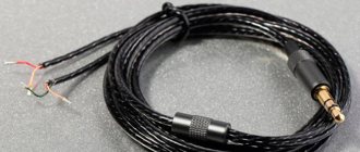
As a result of constant bending of the wire near the 3.5″ Jack plug, noise may appear in the headphones when the connection of the plug to the wire is moved, or even the sound on one of the headphones will disappear completely. Sometimes the common wire breaks, then the sound is distorted: high and mid frequencies disappear almost completely. This happens because the right and left amplifiers of the phone are turned on in antiphase and their output signals almost completely cancel each other out. It also happens that the stereo effect simply disappears. Or there is no sound in the ears, but the microphone works, or vice versa. And sometimes, due to a break in the microphone wire, the control buttons on the headset cord stop working along with the microphone.
If you have such symptoms, we advise you to find a diagram of your plug and re-solder the connector, especially since using these instructions you can do this yourself even without much soldering experience.
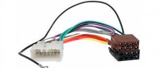
So, a TRS type connector is intended for connecting devices, for example, headphones and a player, with each other. The device consists of a plug (plug) and a socket (jack). Often this connector simply breaks at the point where the wires enter the connector itself. Because of this, either the right or left earphone or both at once may not work for you. Moreover, sometimes extraneous noise appears due to wire breaks in the jack 3.5 connector itself.
In general, it is worth noting that the abbreviation TRS itself comes from the English words: tip (tip), ring (ring) and sleeve (sleeve). Among the Russian-speaking population, the concept has been established that “jacks” are the plug itself, so if you use the original name of the TRS connector in everyday life, many will not understand what we are talking about.
Plug types and applications
Depending on the diameter of the working surface, connectors are divided into:
- Micro jack 2.5 mm . They are equipped with small portable devices such as phones, players, etc.
- Mini jack 3.5 . They are installed in household appliances: computers, TVs, etc. In addition, the pinout of jack 3.5 is extremely simple.
- Big jack 6.35 . Mainly used in professional equipment: electric musical instruments, powerful acoustic amplifiers, but can be built into budget equipment, such as karaoke microphones, metal detectors.
Based on the number of outputs (pin), jacks are divided into:
- Two-pin ( TS ). They transmit an asymmetrical signal, for example, a mono signal is sent to headphones or audio is recorded using a microphone.
- Three-pin ( TRS ). Using them, you can transmit both an asymmetrical signal, with pins 2 and 3 connected by a jumper, and a symmetrical one.
- Four-pin ( TRRS ). They can immediately transmit video and audio information. Modern phones, tablets, video players, etc. are mainly equipped with four-pin connectors.
- Five-position ( TRRRS ). An uncommon connector used by Sony in the Xperia Z smartphone for the simultaneous operation of two microphones, one of which works for noise reduction. TRRS compatible.
There are also two types of sockets: regular, created for a specific type of plug, and with a switch - when the pin is inserted, the device switches from one position to another.
Very often there are situations when Chinese collapsible plugs, which were installed instead of a monolithic broken “jack,” do not completely fit into the sleeve or are poorly fixed. Such situations are possible when the diameters of the sleeve and plug do not match. Therefore, when choosing such a plug, it is advisable for you to check its outer diameter with a caliper along the entire working length.
What are the types of headphone jacks?
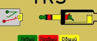
The headphone soldering scheme depends on the plug used to connect the headset to a computer or mobile gadget. TRS connectors, also called jacks, are used as connectors. They are represented by a pointed end in the form of a cone (Tip), turning into a sleeve (Sleeve) with one or several rings in the form of cylinders (Ring) or without them. The rings are separated from each other and from the sleeve by a layer of polymer insulating material.
Depending on the dimensions of the connector, headphone connectors are divided into:
In principle, thanks to the adapters, any headphones can be connected to a standard 3.5 mm jack.
3.5 mm connectors differ in the number of contacts or pins (pin - from English pin) in the form of rings:
How to find out if the connector is faulty
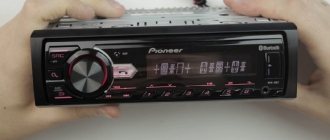
Insert working headphones into the jack and turn on the music. If music does not play in working headphones, your connector is broken. Also, if you hear a hissing sound when the plug moves, this means that the connector will soon fail completely.
Useful: VAZ speed sensor pinout and DS connection diagram
Nowadays, the pinout of headphone wires with a microphone shown in the first picture below is mostly used everywhere, but there is also another one, which is mainly used on old phones and in phones from some manufacturers. They differ in that the microphone and ground contacts are swapped.
How to properly solder a new plug to the headphones (with wire pinout)
It's no secret that the most common malfunction of any headphones (plugs, earbuds or large over-ear ones) is a broken wire near the plug. In this situation, there is nothing left to do except change the plug on the headphones. This is easy and can be done by anyone who has ever held a soldering iron in their hands. The only thing that would be desirable is to understand the intricacy of the wires (in some headphones there are as many as 6 wires under the cable insulation!)
Today we’ll talk about how to solder headphones to a plug without making any mistakes.
You don't need to think about anything, just follow the step-by-step instructions provided and you can easily repair your favorite headphones.
1. Ruthlessly bite off the plug:
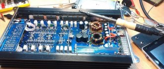
2. How to replace the plug on headphones? For this we will use the old connector. Let's gut it using a sharp stationery knife, ripping it right along the seam. This method allows you to disassemble almost any plug: Open the plastic shell and take out the insides. Do you see a group of contacts with pieces of wire soldered to them? We remember the pinout of the headphone wires (or better yet, write down on a piece of paper which wire was soldered to which contact). Here is the standard wiring of headphone wires by color:
You will find more detailed information about which wire in the headphones is responsible for what later in this article (scroll to the very end).
3. Now you need to clean up the headphone wires a little. What the result should look like:
we connect the common wires (which are in colorless varnish) together and tin the very ends: A few words about how to re-solder the plug on the headphones. It will be bad to pick, because... the wires are covered with varnish insulation. To make the process easier, you can lightly burn the very ends with a lighter.
How to tin wires from headphones using an aspirin tablet, as shown in this video:
4. Now we find an old unnecessary pen somewhere:
and separate the very tip from it:
This will be the body of our new plug.
5. Prepare a piece of heat shrink that will protect the wires from sharp bends at the exit from the plug:
6. It's time to solder the headphone wires to the plug. You need to solder in full accordance with the colors of the wires in the headphones (we remember where which color was soldered or look for our piece of paper where everything is written down):
7. Make sure that everything works. To do this, turn the multimeter into dialing mode, plug the headphones into your ears and alternately touch the probes to different contacts. All sorts of rustling and clicking noises should be heard in different channels.
Or you can try to plug this unfinished plug into your phone or MP3 player and start playing music. In the latter case, it is important to make sure that the right and left channels work independently of each other (use the balance adjustment).
8. If everything sounds as it should , we shrink the heat shrink using a hair dryer or a regular lighter:
9. Apply a couple of drops of epoxy glue: glue everything together and leave for several hours until complete polymerization.
10. We are happy with how we fixed the headphone plug!
Look at the photo of how I managed to solder the new plug to the headphones:
In my opinion, this is the easiest way to fix a headphone plug of all those proposed on the Internet. Despite the fact that the result is quite decent. If you don’t look closely, it’s not even clear that it’s homemade.
By the way, at first I had the idea to make a paste from baking soda and superglue to use it instead of epoxy resin.
But it turned out that this mixture hardens so quickly (almost instantly!) that this option had to be discarded as unsuitable.
That's all. Now you know how to make headphones if the plug is broken and which wire in the headphones is responsible for what. Always try to figure out how everything works, how to repair the plug on your headphones with your own hands, save your money!
Four-wire plug
There are two different options here.
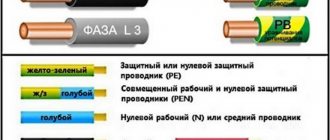
- Ordinary headphones without a microphone and control buttons. 4 wires are connected to the plug: a minus from each copper-colored speaker and a plus (blue with red or green with red). For convenience, the negatives are twisted into one bundle and the result is three wires that need to be soldered to their specific places.
- Headset with microphone. Here the plug has 4 types of contacts: one from each speaker, one for the microphone, and there is room left for soldering a common wire or ground. Schematically, such soldering looks like this:
It should be noted that color marking may vary depending on the imagination of the manufacturer and is very arbitrary. The left channel wire can be green, white or blue. The right channel wire is always marked red. The common wire is copper (varnished or without insulation), but it can also be white if white is not used for the left channel.
Continuity of wires
If the cable breaks, as well as in other cases, it is necessary to determine which wires are connected to the headphones, microphone and control buttons.
There are certain wire color standards that manufacturers adhere to, although they may be violated:
Depending on the model, the wires to the microphone and control panel can be combined or separate, and in different elements of the headphones there can be one or more common wires. A shielded wire can go to the microphone.
Recommendations: How to solder a headphone plug
, How to disassemble headphones: instructions with step-by-step photos of repairing all elements of the headset
, Headphone pinout
Pinout diagrams by manufacturer
Apple audio pinout
- 1 – left
- 2 – right
- 3 – ground
- 4 – microphone
iPod Nano (4th, 5th Gen), iPhone (1st, 2nd, 3rd, 4th Gen), iPod Shuffle (3rd Gen), Cell Phone Connection iPhone headphone (handsfree)
Lenovo audio pinouts
1 – left 2 – right 3 – ground 4 – microphone
Lenovo Thinkpad Edge & X Series Notebook audio
Samsung audio pinouts
1 – left 2 – right 3 – ground 4 – microphone
Samsung Galaxy S I9000, S8500 Wave headset EHS60AVNBE / EHS60ANNWEGSTA / EHS60ANNBECSTD/ GH59-09752A headset Samsung Galaxy S2 i9100 headset should be compatible with Samsung Galaxy Note N7000, Samsung Galaxy Tab GT-P1000, P7100 Galaxy Tab 10.1, 4G LTE, C3530 , [ email protected] 350, Galaxy 551 i5510, Galaxy 550 I5500, E2330, I100 Gem, i220 Code, i350 Intrepid, I9003 Galaxy SL, I9100 Galaxy S II, i997 Infuse 4G, Google/Samsung Nexus S I9023/I9020, [email protected ] 335 S3350, Galaxy mini S5570, Wave 525 S5250, Star II S5260, Wave II S8530, S5780 Wave 578, Wave 533 S5330, Galaxy Gio S5660, Wave 723 S7230, Galaxy Ace S5830, Galaxy Fit S5670, Galaxy S 4G, Galaxy S WiFi 5.0 , R910 Galaxy Indulge, S3850 Corby II, M190 Galaxy S Hoppin, M210S Wave2, M220L Galaxy Neo, M580 Replenish, C6712 Star II DUOS
Samsung i300, i330, i500, i700 handsfree/headset connector
Samsung OEM EHS64 Headset for Samsung Galaxy SIII GT-i9305 and some others
Samsung Series 9 Notebook headset (NP900X3D-A02DE)
Samsung SPH-a420, a580, a640, m220, m240, m300, m320, m330, Rant m540, Exclaim m550 SCH-R451C headset Samsung headset P/N: AEP010SLEB/STD
Samsung SPH-A880, SCH-U620, SCH-U540, SPH-M500, SCH-A950, SCH-A870, SCH-A930, SPH-A920, SPH-A940, SCH-A970, SPH-A900 BLADE, A900M, SCH- A990, SCH-U740 AEP204VBEB/STD Headset/Music
In some Samsung models, the ground contact and microphone can be swapped!
Additionally about the colors of wires in headphones
How to properly solder wires to a headphone plug is out of the question if you are not familiar with the colors of wires in headphones and their meaning (for example, do you know what the green wire is responsible for?)
A different number of wires may come to the headphone plug:
2 wires
I don’t think anyone needs to explain how to repair a headphone plug if they only have two wires. It is basically impossible to confuse anything here.
3 wires
This picture explains even more clearly where to solder the wires to the headphone plug:
Most often, the wires are coated with varnish of different colors:
Of course, there are no strict standards and colors may vary. Here's what it looks like in real life:
Let's see how to properly solder a wire to the headphones (3 wires):
4 wires
If your plug has 4 wires, then there may be options.
In this case, common wires (those of the same color) are connected together and soldered to the common contact of the plug. You should immediately understand how to solder 4 wires from the headphones to the plug from the figure:
Here's how to solder headphones to such a jack:
Schematically, this can be indicated as follows:
And here's how to make a plug on the headphones (correct soldering of headphones when there are 4 wires):
Most often, a microphone wire only looks like one wire, but in reality it is two wires: a thin wire in white PVC insulation completely wrapped in enameled copper wire (in colorless enamel). Something like this:
And in this case, it would be more correct to say that the headphones have not 4 wires, but all 5.
Self-replacement of the 3.5 plug
We will need a knife, soldering iron, solder, rosin. Cut off 5-10 cm of wire from the plug, remove all the insulation from the plug, remember the sequence of wires by color (sometimes they are different). Strip the wires and solder them to the 3.5 mm jack. It is better to fill the soldering area with hot glue and compress it with heat shrink, so the connection will last much longer. Read more about the renovation here
Headphone wiring
Wiring for 2.5 and 3.5 jack plugs
There are only three wires in a regular headphone cable. A plug with this number of pins is also called TRS. The numbering goes from tip to cable:
Instead of three wires, there may be four (two pairs). In this case, one wire from each pair of the same color is considered common and soldered together.
Solder the wires to the appropriate soldering spots. They can be determined visually or with a tester.
The 2.5 plug is designed similarly to the 3.5 and is no different from it except for its size. The wiring is the same on both plugs.
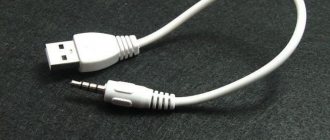
Wiring in miniUSB and miniUSB plugs
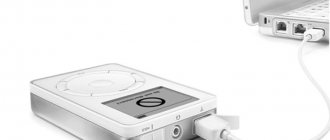
In some mobile phones, headphones with a microphone are connected via mini- and mikroUSB connectors. But you can also connect just headphones to these connectors, for example, to use such a mobile phone as an MP3 player.
The wiring in these connectors is the same. They have five pins to which wires are soldered. They are numbered from left to right when viewed from the side where the wires are connected, and the wires are soldered to 1 (common), 3 (right channel) and 4 (left channel).
Wiring in the 3.5 plug
These plugs have the technical name TRRS. There are two options for wiring these devices OMTP and CTIA. They differ in the connection of the microphone and the common wire, which connect to 3 and 4 wires.
If you connect the wrong type, the microphone will not work and the sound will be muffled.
Cable cutting.
You can prepare a cable in different ways, but the least traumatic method for conductors is to remove the insulation using a soldering iron.
Holding the soldering iron with one hand, rotate the shielded wire around its axis with the other hand, while pressing the insulation against the sharp edge of the soldering iron tip. https://oldoctober.com/
If after this you cannot remove the insulation by hand, you can use side cutters.
It should look something like this.
We also remove insulation from individual wires in the same way.
Now you can give the cable a look suitable for tinning.