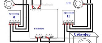
Almost all modern cars are equipped with a sound reproduction system, but in some cases it may be necessary to make a car amplifier yourself. There are many schemes for such devices. Some of them are very simple to repeat and do not contain scarce radio components. Such designs provide satisfactory sound quality when working with wideband speaker systems. You can assemble a sound amplifier in a car with your own hands using transistors or an integrated circuit.
DIY car sound amplifier
Automotive designs are used to work with various sound sources. This could be a radio, mobile phone or FM tuner. Typically, the signal level from the output of these devices is sufficient to drive the output stage, so a preliminary stage is not required in this design, however, tone controls must be present in the circuit. They can be passive or active. Timbre control units assembled on operational amplifiers are very popular. Their disadvantage is the need to use bipolar power supply. Passive controllers based on discrete elements are easy to manufacture and do not require configuration.
A powerful, home-made car audio amplifier must provide such an output signal level that engine noise does not interfere with normal listening. All automotive electronic devices receive power from the on-board network, so the circuits are designed for this voltage. The power output of automotive systems is typically limited to 15-25 watts. This is due to a certain voltage, which is provided by the vehicle’s on-board network. It should be taken into account that the ignition system creates impulse noise, so the input circuits must be well shielded, and LC filters must be installed along the power circuits.
There are automotive systems that provide output power of 100-300 W or more. They require bipolar power supply of 40-60 V, so the circuit contains a pulse voltage converter. Such devices contain a large number of parts, and they are difficult to manufacture and configure. You can make a powerful audio amplifier for a car yourself using complementary pairs of silicon transistors. Complex transistor circuits, powered by a switching voltage converter, provide an output power of 40-50 watts per channel, a linear frequency response in the range of 20 Hz-20 kHz and a total harmonic distortion coefficient of about 0.05%.
I assembled the AC protection according to this scheme
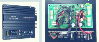
There is no need for configuration if everything is assembled correctly. Printed circuit boards will be archived. When testing the amplifier, I removed 98 watts from one channel, then it went into clipping. As the author stated - pure 100 watts. I used radiators from a computer, from an AM 3+ socket. Without coolers it gets damn hot because the radiators are too small. I decided to leave the cooler running - now everything is warm. The cooler was powered using a PWM regulator circuit using an NE555 timer.
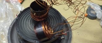
Next, I started assembling the second converter for the subwoofer channel. The scheme remains the same. There are minor changes to the winding of the transformer. I used the same rings, two glued together. The primary remains the same. But the secondary is different, the number of cores is the same, but there are no longer 15, but 21 turns. The output of the converter turned out to be +-70 volts. For the low-pass filter, I wound a separate winding with 0.8 8 turns wire. The stabilization circuit remains as in the circuit. There is also another winding to power the AC protection, everything is the same as in the first converter for Laikov.
Do-it-yourself speaker amplifier for the car
This circuit is designed to reproduce audio frequency signals from a car radio, FM tuner or other electronic device. The variable resistor at the input can be a volume control for a sound-reproducing device. Preliminary signal amplification is performed by a two-channel 548UN1A microcircuit. The pins for the second channel in the manufacture of a stereophonic path are indicated in brackets. The integrated circuit is characterized by a low noise level, a large supply voltage range (6-30 V) and low current consumption. The bass reflex is assembled on two germanium transistors of different conductivities. Reliable transistors of older series can be replaced with more modern analogues.
The signal from the bass reflex collectors is supplied to the semiconductor bases of the output stage. By reducing the capacitance of capacitor C4, you can limit the reproduction of low frequencies. By selecting resistor R4, on the collectors of the output transistors, you need to set half the supply voltage. Powerful transistors are mounted on a common radiator. The input circuits entering the input of the integrated circuit must be shielded. When installing the device on a car, it is necessary to take into account the correct connection of the common wire. “Ground” is made with a thick and as short as possible wire.
You can make a do-it-yourself sound amplifier for a car using a bridge circuit. It does not contain scarce parts and is designed for high-quality sound reproduction in the car.
The design receives power from the on-board network and provides an output power of 12 watts into a 4 ohm load. The capacitances of capacitors C4 and C5 should be about 2000.0 microfarads. In this case, the unit will reproduce a frequency band from 25 Hz to 18 kHz, with a nonlinear distortion coefficient of no more than 0.3%. Silicon diodes set the quiescent current of the output transistors. The power supply circuit contains a fuse and a choke. This is a single-layer winding with PEV wire with a diameter of 1 mm on a ferrite rod 20 mm long and 8 mm in diameter. The following radio components are used in the circuit:
- DA1.1 – DA1.2 – K548UN1A
- VD1 – VD8 – KD521A
- VT1 – VT7 – KT503A
- VT2 – VT8 – KT502A
- VT3 – VT5 – KT819A
- VT4 – VT6 – KT818A
Resistors R2 and R3 change the depth of negative feedback. This operation can be performed by ear.
Motivation
Even though I'm a musician, it doesn't matter to me that I don't own an expensive high-power stereo system.
For many years I used a homemade stereo amplifier based on the TDA1554Q and was very pleased with the sound quality. This amplifier is used for my computer's desktop sound system and also as a radio/video sound system. Meanwhile, the number of audio sources I wanted to connect to my stereo system has increased significantly... then there was a tablet that I use to listen to Internet radio, a music player running on a Raspberry Pi and from time to time I like to listen to podcasts downloaded to my smartphone .
Therefore, your next desktop stereo system should have multiple inputs...about four would be just fine. Also, when watching TV on my computer, I don't want to have to constantly get up to adjust the volume level, but rather adjust it digitally; I would like to use my smartphone as a remote control.
Let's summarize the required parameters and components: – 20-watt stereo amplifier – 4-channel audio input – digital interface for volume control
Powerful DIY car amplifier
The modern element base allows you to independently produce a sound system of sufficiently high power with a minimum number of radio elements. Integral components are used for this purpose. You can make a powerful amplifier in your car using the TDA1562Q chip. This integrated circuit provides a voltage doubling function, which allows the amplifier to develop high output power when powered from the vehicle's on-board network. The design allows you to get up to 70 watts into a 4 ohm load. The circuit has protection against short circuit of the output and short circuit of any of the output wires to positive or body. When the case heats up above 1200C, the device will automatically switch to a reduced power mode, which will not exceed 20 watts. The TDA1562Q chip has the following characteristics:
- Supply voltage – 8-18 V
- Frequency range – 18-40,000 Hz
- Input impedance – 100-120 kOhm
- Output power – 55-70 W
- Nonlinear distortion coefficient at 20 W power – 0.06%
An LED is included in output circuit 8, which lights up when the temperature exceeds the norm, there is a break or short circuit in the load or another emergency situation. Capacitors C7 and C8 consist of two capacitors of 3,300 microfarads connected in parallel. Through the contact block connected between the 4th pin and the power plus, you can control the switching on of the device. To do this, you need to connect any latching switch to the contacts of the block. Capacitors C3, C4 and C6 must be film. The microcircuit is mounted on a radiator with an area of at least 600 cm2. The surface of the microcircuit should be lubricated with KPT heat-conducting paste. A 15 A fuse is placed between the “+” of the battery and the amplifier’s power bus. The input signal, through capacitor C3, is supplied to the input of microcircuit 1 (IN+), and the speakers are connected to pins 7 and 11 (OUT+, OUT-).
This simple stereo circuit contains a minimum of parts and provides up to 40 watts per channel into a 4 ohm load. The device is assembled on a TDA8560Q chip, which is operational at a supply voltage of 8 to 18 volts. It provides a signal gain of 46 dB in the range from 10 Hz to 40 kHz. The distortion factor at a frequency of 1 kHz and an output power of 20 watts does not exceed 0.1%. If the signal is taken from the input of the terminal stage built into the radio, then it should be supplied through resistors with a resistance of 20-50 kOhm. If the signal is supplied from a speaker, then the resistor value should be 150-200 kOhm.
Time has passed...
The amplifier is working and in use. However, it does not reach full power due to the converter being too weak, all due to the transformer having a small core cross-section. The plan is to have a larger transformer and good winding, maybe even toroidal cores. The output voltage of the inverter when connected to an amplifier is 48 V, but with a load it even drops to 36 V, that is, there is a dip in the bass.
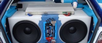
The amplifier, converter and sound timbre control unit are built into a homemade box. The box is made of white furniture chipboard 18 mm thick, everything is connected using Vicol glue and screwed together with wood screws. The box has a capacity of 34 liters and is a bass reflex housing, the hole + pipe is located at the height of the speaker in the rear wall. The box is covered with CarAudio equipment packaging material. There is a connection socket on the back wall.
DIY mini amplifiers for cars
If high output power is not required, then you can make a sound amplifier for your car using inexpensive integrated circuits. One of the possible options is made on the TDA2003 integrated circuit. Its complete analogue is the popular domestic microcircuit 174UN14. The device operates from the vehicle network and provides an output power of up to 10 watts into a 2 ohm load or 6 watts into a 4 ohm load. Frequency range from 40 Hz to 15 kHz. The chip should be installed on a small radiator.
Active subwoofer
The active subwoofer is equipped with a built-in amplifier installed in the same housing as the speaker. On the outside of the case there are potentiometers for smooth adjustment of volume or frequency parameters. Thanks to the controls, the user can configure the device in accordance with the sound parameters of the other speakers in the speaker system.
Main characteristics of active subwoofers
Active devices include, for example, the Mystery MSK-12.3 subwoofer, which has the following parameters:
- speaker diameter - 300 mm;
- power in normal mode - 280 W;
- peak power value - 560 W;
- frequency range - from 28 Hz to 2900 Hz;
- sensitivity - 90 dB;
- The Mystery MK-2.80 amplifier is included in the package.
Advantages and disadvantages
Pros of an active subwoofer:
- Possibility of saving space, since the amplifier is located in the same acoustic housing with the speaker.
- Due to the built-in amplifier, the subwoofer has an expanded range of uses.
- The subwoofer housing has separate outputs for installing standard speakers. Thanks to this, a separate acoustic system can be built based on the active device.
- Various body shapes.
- degraded sound parameters;
- the amplifier and device may overheat;
- amplifier power limitation;
- relatively high cost of devices;
- active devices are equipped with simplified housings.
How to make a car amplifier
Even an inexperienced radio amateur can make an amplifier for car speakers with his own hands. Of course, if there is no practice, then you should start with simple devices made on integrated circuits. Transistor circuits, as a rule, require more complex configuration, whereas integrated systems, when assembled correctly, begin to work immediately. A typical circuit of a simple audio amplifier for a car, with the exception of power filter capacitors, contains only one resistor.
Together with a capacity of 47 microfarads, it should ensure a smooth supply of supply voltage to pin 11 of the microcircuit. In a typical version, different microcircuits can be used. They differ from each other in some parameters, including the input signal level. So the TDA1557 chip requires 50 mV, and the TDA1552 chip needs to be supplied with 500 mV so that it may require a preliminary stage. You can make a car amplifier circuit with your own hands using transistors, but it will be somewhat more complicated.
Firmware
Since the ATTiny2313 does not have a "true" I²C interface (or TWI as Atmel calls it), you should configure the USI (Universal Serial Interface) inside the ATtiny to act as the I²C master controller. I found a very useful project on this topic (many thanks, doctek)
Now the microcontroller polls its serial port (4800 baud) for commands in the format:
[1-4|M][L|R]=[000-255]\n
Examples: ML=000 MR=000
...sets the master volume to zero for the left and right channels
4L=220 4R=180
... sets the input volume for channel 4 to 220 (left) and 180 (right)
You can also pull up the power amplifier's master mute (MM) pin:
MM=TRU
or MM=FLS
How to make a sound amplifier for a car
First, a circuit is selected that must meet the required parameters. You can make a simple sound amplifier for your car radio with your own hands in just one evening. You will need an integrated circuit, a minimum of discrete elements, a simple power supply and a tester. For a complex high-quality transistor unit, measuring equipment is required. In addition to the tester, you will need an oscilloscope, an audio frequency generator, a millivoltmeter and a nonlinear distortion meter. To set up a finished device, an equivalent load is usually connected instead of speaker systems. You can make an audio amplifier for a car with your own hands using only a tester, but in this case you will not be able to obtain a good amplitude-frequency response.