The TDA7294 integrated circuit, according to its characteristics, is a modern single-channel audio amplifier from the famous European company ST Microelectronics. It is used as a basis in class AB ULF Hi-Fi equipment. Has built-in protection functions against short circuit, critical heating and electrical discharges. There is a standby mode when there is no signal at the input and an on/off delay to reduce noise at the output.
For ridiculous money (the price of the device in Russia does not exceed 400 rubles), with the help of a small number of electronic components and a couple of such TDAs, you can assemble a powerful stereo amplifier with good and high-quality sound with your own hands. It is worth considering that currently ready-made modules and soldering kits are sold in radio stores, but their cost is an order of magnitude higher.
Description of the TDA7294 chip
The inexpensive TDA7294 chip is a monolithic integrated circuit in a MULTIWATT15 package. It is intended for use as an AB Hi-Fi audio amplifier. Thanks to its wide supply voltage range and high output current, the TDA7294 is capable of delivering high output power into 4 ohm and 8 ohm speaker impedances.
The TDA7294 has low noise, low distortion, good ripple rejection, and can operate from a wide range of supply voltages. The chip has built-in short circuit protection and an overheat shutdown circuit. The built-in Mute function makes it easy to control the amplifier remotely, preventing noise.
This integrated amplifier is easy to use and does not require many external components to function properly.
Transistor amplification
To increase the current in the load, the circuit on the tda7294 is strengthened. This can be achieved by adding transistors to the output. There are plenty of examples of such improvements on the Internet. The figure shows one of the options.
The rated power of the amplifier in this design, into a load of 4 ohms, reaches 100 W. The coefficient of nonlinear distortion, when operating at a level of up to 80 W, is significantly less than the standard solution. There is no “ladder” type failure in the cascade at all.
There are also alternative solutions on this TDA on the Internet. One of them is the popular inverting amplifier based on tda7294, based on the circuit from the audiokiller project. For an example of assembling such a module, see the video
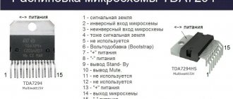
Chip dimensions:
As mentioned above, the TDA7294 chip is available in the MULTIWATT15 package and has the following pinout arrangement:
- GND (common wire)
- Inverting Input
- Non Inverting Input
- In+Mute
- NC (not used)
- Bootstrap
- +Vs
- -Vs
- Stand-by
- Mute
- NC (not used)
- NC (not used)
- +Vs (plus power)
- Out
- -Vs (minus power)
You should pay attention to the fact that the microcircuit body is connected not to the common power line, but to the power supply minus (pin 15)
↑ Printed circuit boards for TDA7297 and TDA7266SA
Today on Aliexpress you can buy both assembled modules based on these chips and kits for do-it-yourself soldering. They cost approx. 1 dollar, a stereo amplifier for that amount is not bad.
↑ UMZCH board with Ali
I consider the board in the kit for a dollar on Ali to be successful, you just need to replace the diode with a jumper.
It’s quite a suitable option, but I don’t like everything about it, as I usually think that the boards I wired for my parts are better.
↑ My printed circuit boards
Since I build boards slowly and for a long time, I first decided to make a working breadboard and evaluate whether it makes sense to continue.
I didn’t like the drawings available on the Internet because the traces go behind the back of the microcircuits, the board will not allow you to screw the transistor to the radiator, the radiator will stand on the board. It will be impossible, for example, to screw the board to the amplifier body. I think it's better to solder the common wire jumper to the bottom of the board.
In the amplifier, you should not place ceramic capacitors in the sound path; film capacitors are needed. They take up more space on the board, although the distance between the pins is 5 mm like ceramics.
I also separated the power supply minus and the common input wire through resistor R3. This is not necessary, but then you need to make a board, exactly like in the datasheet. In boards from the Internet, the common wire is usually routed incorrectly. How critical this is is an open question, but in my boards, when powered by a stabilizer, the background is completely absent, and the noise from the high-frequency speaker is barely audible if you put your ear to it.
Bridge connection diagram
Bridged connection is the connection of an amplifier to speakers, in which the channels of a stereo amplifier operate in the mode of monoblock power amplifiers. They amplify the same signal, but in antiphase. In this case, the speaker is connected between the two outputs of the amplification channels. Bridge connection allows you to significantly increase the power of the amplifier
In fact, this bridge circuit from the datasheet is nothing more than two simple amplifiers to the outputs to which an audio speaker is connected. This connection circuit can only be used with speaker impedances of 8 Ohms or 16 Ohms. With a 4 ohm speaker, there is a high probability of the chip failing.
Typical connection
A typical connection diagram for the tda7294 can be taken from the technical description in the datasheet. The VM and VSBY pins are connected to the positive +VS pin. If there is no power to them or less than 1.5 V, the device is turned off. If the voltage increases above 3.5 V, the microcircuit exits the energy-saving state (StandBy) and quiet mode (Mute).
This design can be assembled using the element base shown in the figure. At the same time, for lovers of deep low frequencies, it should be slightly modified. Below are recommendations for choosing capacitors and resistors that will help you get better sound.
In place of C1, it is advisable to install metallized film capacitors of at least 0.33 μF. The larger the capacity, the better the bass will sound. C2 should be 50V and at least 22uF. On the forums it is recommended to set it to 220 uF. C3,C4 (at 50 V) set the on time. Resistors R4 and R5 have approximately the same purpose; it is better to leave their values at 10 and 22 kOhm, respectively.
PIC capacitor C5 only takes place when the power supply exceeds 40 V. On the diagram it is indicated at 22 µF, but it is better to set 220 µF x 50 V. This will also contribute to the appearance of good low frequencies.
C7, C9 are 0.33 µF film capacitors. C6 and C8 can be omitted. Resistor R1 determines the input resistance. R2 and R3 (their ratio R3/R2) set the gain.
Is your car too noisy? Can you hear the rumble of wheels? Then you need high-quality sound insulation for Volkswagen, from professionals in their field.
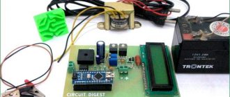
Example of using TDA7294
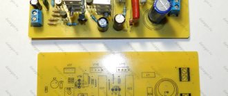
This is a simple 70 watt amplifier circuit. Capacitors must be rated for at least 50 volts. For normal operation of the circuit, the TDA7294 chip must be installed on a radiator with an area of about 500 cm2. The installation is carried out on a single-sided board using LUT technology.
Printed circuit board and arrangement of elements on it:
↑ Idea? A whole ideology!
I want to start with the fact that the very idea of this amplifier did not come to me spontaneously. Rather, it was the result of an analysis of the most interesting in terms of sound circuit solutions that exist today. Let me make a reservation right away: based on the results of assembling many circuits, I have developed my own philosophy in sound reinforcement designs.
First of all, I'm not looking for linearity. Sometimes I even avoid her on purpose. Secondly, I don’t like perfectly precise, sterile, emasculated sound. It is much more interesting to create amplifiers with character, the sound of which is pleasant and recognizable from the first notes. Even harmonics? Let be! Imperfectly smooth frequency response? Spit. The main thing is to like it.
Unfortunately, this approach has to be cut somewhere if you want to be heard by the general public. The amplifier circuit design proposed in this article is designed to reconcile many different groups of convinced supporters of one or another approach.
↑ So, let's consider the postulates of the modern vision of circuit design for budget simple UMZCH.
- The amplifier is implemented on the principle of a powerful op-amp with OOOS, be it discrete or microcircuit. In this case, a powerful microcircuit of a common line will be available to the widest range of radio amateurs.
- Inverting switching is undoubtedly more linear, stable and simply sounds better.
- To increase the input resistance in the inverting connection, it is rational to use a T-shaped feedback loop.
- ITUN is simple to implement on an MS, and undoubtedly sounds much better than classic circuits with OOS in terms of voltage. However, the main difficulty is working on multi-band systems with crossover filters and aggravating the situation of uneven frequency response of the speaker at the resonant frequency. It is also impossible not to note the increase in gain at HF, which immediately scares off many enthusiasts.
- The ground on the board must be routed, undoubtedly, with a star, and all electrolytes must be shunted with film or ceramics.
And, what’s most interesting, with all this, the circuit should be easy to assemble by a wide range of radio amateurs. To be honest, at first I was scared by the prospect of combining all the requirements together without adding complex repeaters, compensators and critical circuits.
But the longer I thought about it, the more real this idea seemed. It took shape in the following thought form - the new mind must combine both current and voltage feedback. Pure OOS in terms of current is unacceptable, since it sharply narrows the choice of speakers used, but it is not worth abandoning it. The gain should not be directly proportional to the load resistance, but, say, proportional to the root of the impedance. In this case, the circuit must undoubtedly be inverting, with a sufficiently high (as far as realistically possible) input resistance. Don't forget about the signal source. There should not be any special requirements for it.
Amplifier power supply TDA7294
To power an amplifier with a 4 Ohm load, the power supply must be 27 volts; with a speaker impedance of 8 Ohms, the voltage should already be 35 volts.
The power supply for the TDA7294 amplifier consists of a step-down transformer Tr1 having a secondary winding of 40 volts (50 volts with a load of 8 ohms) with a tap in the middle or two windings of 20 volts (25 volts with a load of 8 ohms) with a load current of up to 4 amperes. The diode bridge must meet the following requirements: forward current of at least 20 amperes and reverse voltage of at least 100 volts. The diode bridge can be successfully replaced with four rectifier diodes with the corresponding indicators.
Electrolytic filter capacitors C3 and C4 are designed mainly to remove the peak load of the amplifier and eliminate voltage ripple coming from the rectifier bridge. These capacitors have a capacity of 10,000 microfarads with an operating voltage of at least 50 volts. Non-polar capacitors (film) C1 and C2 can have a capacity of 0.5 to 4 µF with a supply voltage of at least 50 volts.
Voltage distortions should not be allowed; the voltage in both arms of the rectifier must be equal.
(1.2 MiB, downloads: 5,845)
↑ About sound
Of course, they are inferior to audiophile amplifiers.
But the sound is without obvious distortion and not annoying. All frequencies are reproduced, especially low ones. But the sound seems to be purified, simplified, smoothed out. There is no “air”, “liveness” and microdynamics. But the disadvantages when listening to high-quality recordings turn into advantages when listening to MP3s and corresponding acoustics. The detail and transparency of higher-end amplifiers can only highlight the MP3's shortcomings.
I have my own “standards” for determining power (I was surprised to actually find confirmation on some datasheets), my own “musical” power, but it is fundamentally different from the bloated PMPO. For these amplifiers, my power rating is 1...2 W, and this is enough for home listening on acoustics with a sensitivity of about 90 dB.