Author L. Borisov city of Omsk.
Tube amplifier SE (single-ended) from available parts, class A, without feedback
For this amplifier, the most affordable lamps were chosen, these are 6P15P and 6N2P, and 6P15P differs from the 6P14P lamp for the better. The wonderful Russian lamp 6P15P has gold-plated grids, a larger number of turns on the grids in relation to the anode area, has a greater slope of the current-voltage characteristic, and greater emission. The sound obtained with the 6P15P lamp is more detailed and faster than with the 6P14P.
Design: Single-ended tube three-stage amplifier without negative feedback circuits. The input stage is implemented on double 6N2P triodes (one for each channel), the driver is a cathode follower, the output stage is implemented according to an ultra linear circuit on 6P15P pentodes (four each). The driver is implemented on the second triode in the form of a cathode follower, which significantly improves the matching of the cascades, and most importantly does not reverse the phase of the driver output signal, which makes it possible to compensate for the nonlinearity of the current-voltage characteristics of the driver and output lamps. This reduces overall THD (non-linear distortion). The TS-160 power transformer was taken ready-made (from a tube TV), and winding 11-12 needs to be rewound without disassembling the transformer with a thicker wire d = 1.2 mm, along the top. This winding is needed to power the filament of two 6N2P input lamps. The TS-160 power transformer must be suspended on rubber feet and isolated from the chassis to reduce microphone and electrical interference. The output transformer is also taken from a ready-made TS-180 (this is a power transformer from a tube TV), and the core needs to be disassembled and one coil rotated 180 degrees. You need to assemble the magnetic circuit with a gap of 0.2 mm, from non-magnetic gaskets (paper gaskets are also suitable). Windings 10 - 9 and 10″- 9″ need to be rewound along the top with wire d = 1.8 mm, 22 turns each. For the circuit in Fig. 1, it is advisable to select the output lamps in pairs.
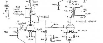
Fig 1. (to increase the size of the diagram, click on it)
If you have highly sensitive acoustics with a sensitivity of more than 95 dB, then the amplifier circuit can be simplified, see Fig. 2. The input stage in this circuit has different operating modes, there is no pass-through capacitor between the anode of the first triode and the driver, which improves sound detail, but this is only noticeable on high resolution speaker systems.
Fig 2. (to increase the size of the diagram, click on it)
Features: SE amplifier is designed for high-quality amplification of music programs from CD players. For high-quality sound reproduction, the SE amplifier requires speakers with a sensitivity of 90 dB/W.
Very good results were obtained with JAMO Classic 8 speaker systems.
An even better result was obtained with Horn 4a32_1a20-S_PT25B-2-S horn loudspeaker systems, where new natural silk diaphragms were installed in the midrange and high-frequency speakers.
Obtained technical characteristics:
Nominal output power in class A (4 Ohm load, 8 Ohm load)
| 2x10 W | |
| Frequency range (flatness -3 dB) | 20 Hz - 100 kHz |
| Input sensitivity | 150 mV |
| Signal to noise ratio | 80 dB |
| Harmonic Distortion (at -10 dB), at f = 10 kHz, into 4 ohms with -3 dB feedback | 0,1% |
| no feedback | 0,21% |
| closed-loop intermodulation distortion factor -3 dB | 0,36% |
| open-loop intermodulation distortion factor | 0,37% |
| Harmonic Distortion (at -10 dB), at f = 1 kHz, into 4 ohms with -3 dB feedback | 0,35% |
| no feedback | 0,65% |
| closed-loop intermodulation distortion factor -3 dB | 0,4% |
| open-loop intermodulation distortion factor | 0,47% |
Good features: The harmonic distortion coefficient at a load of 8 ohms is almost two times less than those indicated in the table at a load of 4 ohms.
For additional information you can contact E-mail
To main
When using article materials, a link is required.
6P15P is also simple
In this note I will try to show a small handful of circuits for amplifiers of extremely high quality, suitable for repetition. The basic scheme for presentation can be either Williamson’s invention or a short cut with a full-fledged bass reflex. Finger pentodes of this series have good sensitivity and relatively low distortion, which makes it possible to simplify the circuit design. A common characteristic of all circuits will be the use of a differential pair of low-frequency transformers as a matching unit between the load and the tube stage. To get a general idea of differential inclusion, you can look at the articles of Sergei Komarov in Radio magazine for 2005-2006. Quite a lot of information on this topic is presented here on the site. Regarding the question of the need to use a differential output unit in a push-pull tube amplifier, there is a simple and unambiguous answer for me. A differential pair is the simplest and most effective solution to the problem of ensuring high quality amplifiers while extracting the maximum possible power from the output stage tubes. When designing a tube amplifier, you should not engage in any hand-to-hand winding work, because it is extremely difficult to “invent” a symmetrical diff pair manually. And the procedure for winding a transformer itself has a household analogy in the form of overhaul and modernization of a serial engine for a VAZ car. Why do this in the 21st century? There are other effective standard solutions that provide quality at the Toyota level.
Below are examples of circuits built using differential output. For some time now I have completely ceased to be interested in the classic push-pull arrangement with an ordinary transformer. Even despite its relative cheapness. It is simply banal and to achieve high-quality sound from it you need to work hard on the transformer. But in differential inclusion there is no such problem in principle. But choosing a symmetrical pair of matching transformers turned out to be easier for me. The first option is built according to an ultra-linear scheme. Single lamps of a push-pull cascade will not allow you to obtain an undistorted output power of more than 12 W.
It is not recommended to raise the anode voltage in such a circuit too high due to the shielding grids. To drive the output stage, one dual triode is sufficient. The offset shown is combined, but this is a matter of taste. But in the following circuit, the anode voltage can be raised higher, since the feedback circuit allows this. I couldn’t find any reason to increase the depth of the OS on screen grids above 3-5 percent, so we can leave it that way. But when using auto-bias, it is necessary to install shunt electrolytes in the cathodes of the output stage to coarse the feedback in current and improve the frequency response in low frequencies.
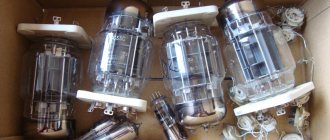
The appearance of the 6P15P output pentode, its connection diagram and plastic sockets for printed circuit wiring are shown in the figure. These are ordinary finger lamps. The external similarity of the 6P15P and 6P14P lamps is almost perfect, and the pinout is the same. You can replace 6P15P with 6P14P. The replacement will not be exactly equivalent, but in most cases there will be no special problems, and no one will be able to tell the difference. If you adjust the mode, the result can be improved. Lamps 6P15P and 6P14P have a high-voltage design, compared to 6P18P. Therefore, the amplifier circuits for these lamps are significantly different. There is no difference in the packaging of lamps, subject to proper storage conditions in a dry, heated room, for almost 50 years. Of course, the operating parameters of the lamps deteriorate somewhat over time. You shouldn't expect miracles here. But the reliability of maintaining a vacuum is quite good. There is a tendency to inflate price tags when selling lamps with EB indices and others. Instrument measurements have shown that this is unfounded. Since the use of the lamps is assumed to be the same - for sound, there is no difference in the letters. The excessive variety of prices is due only to shameless marketing. The parameters of lamps with different letters in the indices may differ slightly, but in general, the operating parameters of most working lamps fit into the datasheets. Therefore, I see no reason to pay 5-10 times more for letters on glass. The main thing is to test real operating parameters on a measuring device, perform a basic service check and select symmetrical copies of the same type of lamps. It makes sense to carefully study the internal design of the lamp. Lamps of different designs should not be placed in pairs that are symmetrical in mode. In dynamics, the result may be negative. To obtain increased power from finger lamps, you can use them in parallel. An example of a circuit with higher power transformers is shown below. In this configuration, the available output power can reach 40 W, with a 200 W power supply across the anodes.
6P15P finger pentodes are similar to the bourgeois EL84 lamp. But the price of domestic glass and Soviet vacuum can be an order of magnitude lower. I have supplies. Here finger lamps can only be purchased in matched pairs. And you can buy a tube amplifier with 6P15P light bulbs here at a price of 35K and above. To do this, just contact me by phone and then by mail, discuss the price of the product and delivery conditions, pickup is possible. After this, those who want a relationship should credit their phone account with 1% of the transaction amount. An advance payment of 20-99% of the agreed amount to my Sberbank account is made after reaching an agreement. Having received the transfer on my phone, I can contact the buyer promptly if necessary. Then, within the agreed upon timeframe (up to two weeks), I call myself to confirm that the product is properly packaged and ready for shipment. And I am sending photographs of this particular unit by email, open and packaged. Before shipment, the buyer is in any case obliged to transfer the remaining amount, after receiving which I carry out the shipment and email a copy of the receipt. If the buyer's circumstances have changed within the specified period of time, then the purchase can be refused. The listed deposit is not refundable. The hardware is guaranteed for 12 months from the date of delivery. The warranty does not apply to glass sent by post or transported by a transport company. Sincere wishes to everyone for good health and success.
Evgeny Bortnik, Krasnoyarsk, Russia, January 2018
Power amplifier for two 6p45s
The power amplifier for two 6p45s was designed for everyday on-air operation. In addition, it can be recommended for repetition by beginning shortwave radio amateurs. The amplifier uses 6P45S tubes, which are affordable, have good linearity and a huge operating life (5000 hours). They can be used even after many years of work in the line scan unit of televisions. The power amplifier on two 6p45s has an output power of 200 W on all HF bands with an input power of 30 W and is assembled in a housing available to the author with overall dimensions of 193x393x270 mm.
Often, beginning radio amateurs (and not only) purchase an inexpensive imported transceiver that does not have a built-in antenna tuner (automatic matching device). Based on this, a power amplifier based on two 6p45s uses a circuit for connecting lamps with a common cathode, in which the excitation voltage is supplied to the control grid. The amplifier allows you to “unload” the transceiver by decoupling it from the antenna. In fact, as they say now, it is an active antenna tuner. Among other things, the transceiver is protected from static electricity charges at the antenna terminals and other troubles associated with this (for example, a break in the antenna or a short circuit in it). In the event of a breakdown of the lamps (an incident unlikely when using 6P45S lamps), such a circuit solution is much safer for the transceiver than a circuit with common grids.
The schematic diagram of a power amplifier using two 6p45s is shown in the figure. The input signal through the RF connector XW1 and relay contacts K1.1 is supplied to two low-pass filters with a cutoff frequency of 32 MHz, which are made in the form of P-circuits, the input and output resistances of which are 100 Ohms. At the amplifier input, the P-circuits are connected in parallel, therefore, the input impedance is 50 Ohms. The circuit does not contain capacitors with a capacity of about 60 pF included in the low-pass filter. In reality, these capacitors are formed by mounting and other capacitances. The input capacitance of the low-pass filter is formed by the capacitance of the coaxial cable, through which the output of the transceiver is connected to the input of the amplifier, as well as the mounting capacitance and the capacitance of the K1.1 relay contacts, which totals 120 pF. The linear capacitance of the RK50-3-13 coaxial cable is 110 pF/m, therefore, the length of the cable connecting the transceiver to the power amplifier on two 6p45s should be about 90 cm. More precisely, the cable length is selected according to the minimum SWR when tuning the power amplifier on two 6p45s.
The output capacitance of each low-pass filter includes the lamp input capacitance (55 pF) and the mounting capacitance (approximately 5 pF), for a total of 60 pF. The use of low-pass filters is useful for several reasons. Firstly, to reduce the level of higher harmonics, and secondly, to compensate for the capacitance of the coaxial cable connecting the amplifier to the transceiver, the length of which should not exceed 0.1 of the shortest wavelength of the amplified signal, i.e. 1 m. When this condition is met, the cable represents a capacitance and does not transform the input impedance of the amplifier. Thirdly, the low-pass filter compensates for the input capacitance of the lamp, as a result of which the input impedance of the amplifier becomes frequency-independent, and the amplitude of the exciting signal does not decrease with increasing frequency. It is obvious that the use of a low-pass filter is justified.
The low-pass filter outputs are loaded with resistors (R7 and R10, respectively). From these resistors, through capacitors C7 and C9, alternating HF voltage is supplied to the control grids of lamps VL1 and VL2. The gain of each tube is 6.7 times the power (approximately 8.2 dB). This, of course, is not much and is comparable to the gain when operating lamps with common grids, but it is justified by the very stable operation of the amplifier. In addition, its input part is simplified. The task of filtering spurious oscillations at the amplifier input was not set, because The output circuits of the transceiver cope with this, although some filtering of higher harmonics, of course, occurs.
This construction of a power amplifier using two 6p45s has another advantage, namely that the throughput capacitances of the lamps are not summed up, which happens when the lamps are connected in parallel. Consequently, the stability of the amplifier is further increased.
The P-circuit uses a combined (for the 28 MHz range) series-parallel power supply circuit. The resonant resistance of the P-circuit is 600 Ohms. The anode choke has no parasitic (parallel or series) resonances in the frequency range from 1.5 to 30 MHz. On the HF ranges, part of the inductor Dr2-1 is short-circuited with alternating current using an additional band switch biscuit and capacitor C14. In addition, with the help of this biscuit, an additional capacitor C16 is connected to the “hot” end of the P-circuit when operating on the 80-meter band. The resonant frequency of the circuit formed by capacitors C13, C14 and part of the inductor Dr2-1 is about 600 kHz, and for frequencies above 14 MHz (and much lower) its resistance to alternating current is practically zero.
The use of a switchable anode choke in combination with other measures taken made it possible to obtain the same output power (200 W) on all HF bands. The DrZ choke and capacitor C12 serve to protect the power supply in case of possible self-excitation of the VHF amplifier. An RF voltmeter is installed at the output of the P-circuit for ease of adjustment. In transmission mode, when the pedal is pressed, an electronic key made on transistors VT1 and VT2 is activated. Transistor VT2 opens, and relay K1 - KZ, included in its collector circuit, is activated. The contacts of relay K3.1 (Fig. 2) are switched, and the power supply voltage is supplied to the lamp screen grids from a voltage stabilizer made on transistor VT1. A parallel type stabilizer, which provides protection for lamps during the dynatron effect of the anode or screen grid, despite its simplicity, works well. Resistor R9, which is connected to the output of the stabilizer, facilitates the thermal regime of transistor VT1 in receive mode.
Of course, it would be possible to use a parallel-series voltage stabilizer, which is more economical than a parallel one, but also much more complicated, because contains actually two stabilizers. In the opinion of the author, such constructive complication with not very significant savings is inappropriate. The operation of the stabilizer can be improved by using, instead of ballast resistor R5, a light bulb with the appropriate voltage and current, which will play the role of a barter, increasing the stabilization coefficient. In fact, a parallel voltage regulator is simply a powerful high-quality zener diode, the current through which (62 - 70 mA) is set using ballast resistor R5.
The power transformer Tr1 of the power supply is connected to the network smoothly through the limiting resistor R1, which, some time after switching on, is short-circuited by the contacts of the toggle switch B1 with the middle neutral position. Such a simple connection circuit significantly extends the life of lamps and power transformers, and the entire amplifier as a whole. It is known that the filament of a cold lamp has a resistance ten times less than a heated filament. Therefore, the inrush current of the lamp filament is ten times the rated filament current. A large surge of current at the moment the voltage is applied overloads the filament, destroys its structure and reduces the life of the lamp. Therefore, the use of soft start is more than justified.
At the input of the power transformer, a network filter is installed, made on two winding inductors Dr1 and capacitors C1 and C2. The anode power supply has protection against excess anode current. Resistor R11 (Fig.) limits the current during breakdown or short circuit of the output of the anode voltage source at 600/10 = 60 (A). The FR207 type diodes used in the power supply (Fig.) will withstand this current pulse and will not fail. The anode voltage source is composed of two, 300 V each, connected in series, which improves the dynamic characteristics of the power source.
On the rear wall of the case there is a power amplifier with two 6P45S, opposite the 6P45S lamps, an M1 fan for 24 V is installed, working for exhaust. It turns on when the power amplifier operates for a long time using toggle switch B2. To reduce acoustic noise, the fan is powered by a voltage of 20 V. The fan is secured through a soft felt pad. In addition, the screws that secure it to the back wall are equipped with polyethylene tubes and two washers each made of felt and textolite. Thus, the fan housing is completely isolated from the metal surface. In the case of using a fan with a plastic casing, this is desirable, but if the casing is metal, then such fastening is mandatory. 6P45S lamps are installed on a plate made of double-sided fiberglass, for which a 125x65 mm cutout is made in the chassis. All voltages are supplied to the lamps through feed-through capacitors (except, of course, for the excitation voltage, which is supplied by a coaxial cable with a diameter of about 4.5 mm with fluoroplastic insulation). Relay K1 is located near the input connector XW1 (Fig.).
All parts related to the high-frequency unit are interconnected by 20 mm wide busbars, which are cut from tinned tin from instant coffee cans. The cathodes of the lamps, the current collectors of the variable capacitors included in the P-circuit, the antenna connector, the “ground” terminal, and the blocking capacitors in the anode choke circuit are connected to the busbars. Particular care should be taken to connect the current collectors of the KPIs, the grounded terminals of additional capacitors connected to them, and the cathodes of the lamps to the bus. Considering that a large loop current flows between the grounding points of the KPI and the cathodes of the lamps, other parts going to the housing should not be grounded between them. Due to the large total output capacitance of two 6P45S lamps (about 40 pF), a significant part of the loop current (about half at 28 MHz, much less in the low frequency ranges) flows through the bus section between the anode KPI and the cathodes of the lamps.
Inductors L1 and L2 of the input low-pass filters each contain 12 turns of PEV-2 1.2 mm wire. Winding diameter - 10 mm, length - 20 mm. The winding is frameless. Both low-pass filters are enclosed in one common screen and located under the chassis, near the lamp panels.
All inductors of the P-circuit are wound in one direction, the taps are counted from the “hot” end. Coil L3 - frameless (diameter - 26 mm), wound with silver-plated wire 03 mm on a mandrel, winding length - 30 mm, number of turns - 4. Anode KPI, which uses one section from an old-style two-section variable capacitor with a gap between the plates not less than 0.5 mm, soldered to the tap from one turn of coil L3. This connection reduces the influence of the initial capacitance of the KPI on the resonant frequency of the P-circuit in the range of 28 MHz.
Coil L4 is frameless (diameter - 40 mm), has 4.5 turns of PEV-2 wire 02 mm, tap - from the 3rd turn, winding length - 27 mm. Coil L5 is wound on a 45 mm frame and contains 5+5 turns, the wire diameter is 1.5 and 1.0 mm, respectively. The winding pitch is 5 mm, the winding length is 50 mm. The anode choke is wound on a fluoroplastic rod with a diameter of 18 mm, the winding length is 90 mm, the wire is 0.4 mm, the tap is from the middle.
Power transformer Tr1 is made on a magnetic core ШЛ32х40. Its skein data is given in the table.
The line filter choke is designed somewhat unusually. It is wound with a double network wire from a burnt-out electric soldering iron on a 08 mm ferrite rod from the magnetic antenna of the radio. The length of the rod is at least 120 mm. Before winding, the ferrite rod is wrapped in several layers of varnished cloth. At first, the inductor is wound as usual, but when the winding reaches the middle of the rod, the winding direction is reversed. To do this, the wire is bent in the middle of the throttle, the loop is secured with a strong nylon or silk thread. Then, if the winding was carried out clockwise, after the middle of the length of the rod it is wound counterclockwise. The inductance of the inductor remains quite large, but magnetization of the ferrite rod and its saturation due to a possible insufficient cross-section are completely eliminated. Consequently, all nonlinear effects and changes in the inductor inductance when the load on the line filter changes are completely eliminated.
The power amplifier on two 6p45s operates in class B. The quiescent current of the lamps (80 - 100 mA) is set using a variable resistor R13. The bias voltage is about -45 V. The use of additional resistors R14 and R15 completely eliminates the erroneous setting of the bias voltage and its loss when the contact in the variable resistor R13 is broken.
At the input of the power amplifier using two 6p45s, between the connection point of the lower (according to the diagram) terminals of the coils L1 and L2 and the common wire, a capacitor with a capacity of about 120 pF, made up of 3 KT-2 capacitors, is installed. The capacity of this capacitor is specified when tuning the amplifier in the 28 MHz range according to the minimum SWR in the cable connecting the transceiver to the power amplifier. It is advisable to carry out the adjustment with well-warmed lamps. The low-pass filter is adjusted by selecting the inductance of the coils L1 and L2, as well as the cable length.
The P-circuit should first be adjusted in a “cold” way [2]. The stand diagram is shown in Fig.Z. When setting up the P-circuit, you should not, as some authors recommend, disconnect the lamps and the anode choke and replace them with an equivalent capacity. Firstly, it is difficult to accurately measure this capacitance, and not all radio amateurs have a capacitance meter, and secondly, the anode choke in the parallel power circuit is connected precisely in parallel to the P-circuit coils (via blocking capacitors C12 and C15). Consequently, a loop reactive current flows through it, depending on the magnitude of the alternating voltage at the anode of the lamp and the inductance of the inductor itself.
As is known, when two (or several) coils are connected in parallel, their total, total inductance decreases and becomes less than the inductance of any of the parallel-connected coils. It is clear that the greatest decrease in the inductance of the P-circuit will occur in the range of 1.8 MHz. In the 28 MHz range, the effect of the anode choke on reducing the inductance of the loop coil is insignificant, is within the error limits of the measuring instruments, and can be neglected.
If coils L3 - L5 are made exactly as described, setting up the P-circuit comes down to checking the resonance in the middle of each range. For this purpose, a heterodyne resonance indicator (HRI) is suitable, which, despite its simplicity, is a universal high-frequency device and is completely undeservedly forgotten at the present time. Don’t forget about the neon light bulb, which, when mounted on a long fiberglass stick, is an excellent peak indicator of high-frequency voltage and allows you to accurately determine the moment of fine-tuning the P-circuit to resonance, or, for example, the appearance of self-excitation. By the color of its glow, you can approximately determine the frequency of self-excitation. At the operating frequency, the glow of a neon light bulb has a yellowish-violet color, and when self-excited on VHF, its glow takes on a bluish tint.
The anode current of the lamps with a detuned P-circuit should be about 600 - 650 mA, with a tuned P-circuit - no less than 535 - 585 mA, i.e. The “dip” of the anode current during the P-circuit setup process should not exceed 65 mA, because in this case, a redistribution of the anode current occurs “in favor” of the current of the lamp screen grids. Therefore, a higher current of the screen grids will cause them to be overloaded with power, which is undesirable.
You should not strive to achieve an output power of more than 200 W. However, by increasing the anode voltage to 900 - 1000 V and accordingly changing the P-circuit data, an output power of 300 W can be obtained in SSB mode. But the reliability of the amplifier decreases, because the maximum permissible power dissipated for a long time at the anode of one lamp is only 35 W. Therefore, using this mode is not recommended, and the difference in the level of emitted signals is not so great.
Radio circuits Electrical circuit diagrams
category Amplifier circuits materials in category * Subcategory Tube amplifier circuits
Source: Radioamator 1999. 40 best designs of tube UMZCHs over 40 years
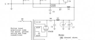
Below is a diagram of a lamp UMZCH. Author - G. Krylov. Its output power is 6 W with a nonlinear distortion coefficient of 3%; at an output power of 4 W, the THD is 1%. The unevenness of the frequency response in the range from 25 Hz to 16 kHz is 1 dB. Input sensitivity is 170 mV. Background level -55 dB.
A special feature of the amplifier, which consists of a pre-amplifier stage, a push-pull output stage and a rectifier, is a unique excitation circuit for the final stage without the use of a bass reflex.
The signal from the volume control R1 is fed to the control grid of the 6Zh1P type lamp, amplified by it and sent to the control grid of the 6P15P type output lamp L2. The signal voltage from the cathode of lamp L2 is further supplied to the cathode of lamp L3.
The signal voltage U supplied to lamp L3 can be determined from the formula: U= (I1 - I2)(R7 + R8), where I1 and I2 are the alternating components of the currents L2 and LZ.
It is not possible to increase this voltage, since for good use of lamp L3, the current I1 must be close to I2, and it is impossible to increase the resistance of resistor R8 due to a decrease in the anode voltage. Therefore, this circuit is of interest only when using lamps with a high transconductance, operating at a low excitation voltage. Of the common lamps, the 6P15P pentode satisfies this requirement.
To reduce nonlinear distortion and reduce output impedance, the amplifier is covered by negative feedback with a depth of 14 dB. The feedback voltage is removed from the secondary winding of the output transformer and fed through a resistor to the cathode of lamp L1.
The power transformer is assembled on a core made of Ш32 plates, the thickness of the set is 32 mm, the window is 16x48 mm. The network winding contains 880, and the anode winding 890 turns of PEL 0.33 wire, the filament winding consists of 28 turns of PEL 0.8 wire.
Output transformer design
The output transformer (Fig. 14) is made on a core made of Ш26 plates, the thickness of the set is 26 mm, the window is 13X39 mm. The primary winding contains 1200X 2 turns of PEV-2 0.19 wire, the secondary winding contains 88 x 3 turns of PEV-2 0.47 wire. It is necessary to strictly maintain the equality of the numbers of turns of the sections of the secondary winding and connect the sections in parallel.
The amplifier is mounted on a 1.5 mm thick aluminum chassis measuring 240x92X53 mm. The first stage should be as far as possible from the power and output transformers. The housing of potentiometer R1 should be connected to the chassis.
The distance between the power and output transformers must be at least 15 mm. The axes of their coils must be perpendicular.
Setting up an amplifier comes down to adjusting the amount of feedback by changing the resistance of resistor R10. If the amplifier is excited, the terminals of the secondary winding of the output transformer should be swapped. To avoid self-excitation of the amplifier at ultrasonic frequencies, the feedback depth should not be more than 15 dB.
The bridge rectifier using D209 diodes can be replaced with a selenium rectifier ABC - 120-270. It is advisable to replace capacitors C5, C6 with one capacitor with a capacity of 150 μF for a voltage of 300 V. The loudspeakers of the acoustic unit should have a total impedance of 8-10 Ohms. The author used two 5GD10 loudspeakers connected in series.
ULF on G. Krylov lamps 6Zh1P, 6P15P (4W)
Below is a diagram of the UMZCH for playing G. Krylov’s recording. Its output power is 6 W with a nonlinear distortion coefficient of 3%; at an output power of 4 W, the THD is 1%. The unevenness of the frequency response in the range from 25 Hz to 16 kHz is 1 dB. Input sensitivity is 170 mV. Background level -55 dB. A special feature of the amplifier (Fig. 13), which consists of a pre-amplification stage, a push-pull output stage and a rectifier, is a unique excitation circuit for the final stage without the use of a phase inverter.
The signal from the volume control R1 is fed to the control grid of the 6Zh1P type lamp, amplified by it and sent to the control grid of the 6P15P type output lamp L2. The signal voltage from the cathode of lamp L2 is further supplied to the cathode of lamp L3.
The signal voltage U supplied to lamp L3 can be determined from the formula: U= (I1 - I2)(R7 + R8), where I1 and I2 are the alternating components of the currents L2 and LZ.
It is not possible to increase this voltage, since for good use of lamp L3, the current I1 must be close to I2, and it is impossible to increase the resistance of resistor R8 due to a decrease in the anode voltage. Therefore, this circuit is of interest only when using lamps with a high transconductance, operating at a low excitation voltage. Of the common lamps, the 6P15P pentode satisfies this requirement.
To reduce nonlinear distortion and reduce output impedance, the amplifier is covered by negative feedback with a depth of 14 dB. The feedback voltage is removed from the secondary winding of the output transformer and fed through a resistor to the cathode of lamp L1.
The power transformer is assembled on a core made of Ш32 plates, the thickness of the set is 32 mm, the window is 16x48 mm. The network winding contains 880, and the anode winding 890 turns of PEL 0.33 wire, the filament winding consists of 28 turns of PEL 0.8 wire.
The output transformer (Fig. 14) is made on a core made of Ш26 plates, the thickness of the set is 26 mm, the window is 13X39 mm. The primary winding contains 1200X 2 turns of PEV-2 0.19 wire, the secondary winding contains 88 x 3 turns of PEV-2 0.47 wire. It is necessary to strictly maintain the equality of the numbers of turns of the sections of the secondary winding and connect the sections in parallel.
The amplifier is mounted on a 1.5 mm thick aluminum chassis measuring 240x92X53 mm. The first stage should be as far as possible from the power and output transformers. The housing of potentiometer R1 should be connected to the chassis.
The distance between the power and output transformers must be at least 15 mm. The axes of their coils must be mutually perpendicular.
Setting up an amplifier comes down to adjusting the amount of feedback by changing the resistance of resistor R10. If the amplifier is excited, the terminals of the secondary winding of the output transformer should be swapped. To avoid self-excitation of the amplifier at ultrasonic frequencies, the feedback depth should not be more than 15 dB.
The bridge rectifier using D209 diodes can be replaced with a selenium rectifier ABC - 120-270. It is advisable to replace capacitors C5, C6 with one capacitor with a capacity of 150 μF for a voltage of 300 V. The loudspeakers of the acoustic unit should have a total impedance of 8-10 Ohms. The author used two 5GD10 loudspeakers connected in series.
Source: Radioamator 1999. 40 best designs of tube UMZCHs over 40 years.