6С33С – what do we know about it?
The domestic reference book says: “Triodes for operation as a control lamp in electronic voltage stabilizers.” Brief, concise, incomprehensible. You can turn the page.
Foreigners are more knowledgeable: “Triode, Formerly used in the power supply of the main radio unit of the MIG 25 Military Aircraft” What does freedom of information mean!
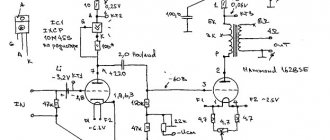
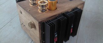
↑ Double push-pull monoblock on 6С33С with power supply..., well, of course!, from impulse generators
It all started a very long time ago, when I tried to saddle the first octal, represented by 6P3S-E, in a clumsy push-pull with relay switching of the triode-pentode output stage mode (I was toiling around with foolishness, huh?) ... In general, preparing this combine for harvesting , I wandered around the bazaar in search of materials for the case, and there, from one radio components dealer, I bought a pair of new 6S33S.
In boxes. Even then he told me, smiling slyly, “thing!” But I didn’t know this yet! Naturally, there were no panels, and I could not use this miracle for a very long time. So they lay on my shelf until thrifty suppliers brought to the markets what had been lying in warehouses and back rooms since the collapse of the union. I finally got what I've been wanting to get for years.
By that time, I had already disassembled and assembled, or assembled and disassembled several dozen amplifiers of various calibers and purposes, had slightly mastered pulse power supplies, and even assembled a 6s41s amplifier. Naturally, thinking that I was already incredibly cool, I decided to assemble a 6c33c amplifier. The concept in general terms was clear. I'm doing RR. At this point, someone will think “why just RR, you can make an SE on it and get 12W of power?”
Without going into details, I will say: to get a normal low end, you need to have a hard speaker. Hard speaker - low sensitivity - higher required power to drive it. And I love the bottom... And any RR sounds more lively than SE. All this has been tested practically, so the choice was clear. If I had known then how many surprises the “horned one” would have in store for me, I would have quit without a second thought. And maybe even herself against the wall.
But I started with trances. This was my first mistake. Already now, having assembled it, I will shout out loud “start with the power supply, trances later!” But then... Power transformers from TU-100-BU4 amplifiers were chosen for the role of trances.
Having sorted them out, I became despondent. The technical cardboard reel was so scary that it almost ended up in the trash. There she is, in the foreground. On the right are fiberglass frames made to its dimensions.
Remembering that for lamps with low Ri the trans turns out to be simpler, having gathered together the experience of transformer-building monsters and the existing wire, I wind a sweet couple. So trans. Window: 40*55mm Primary: 300+300+75+75+300+300 turns Secondary: 80+35 Raa - 1.1 kOhm at 4 Ohms. Everything is wound with PEV2-0.6mm wire.
Winding pattern:
“What’s so clumsy?” you ask. I was not sure until the last moment that 26 layers would fit on the reel, as was calculated. Fits 24 almost end to end with insulation. And having wound the secondary at 4 and 8 ohms, I wanted to play Raa in different modes. I don't have any speakers with 8R impedance.
Having started to assemble the chassis around the trances, I made a second mistake, but more on that later.
You can pay attention to the shelf that is above the transformers and is limited at the top by two corners. This is the place for the future super BP. Exactly! After all, having estimated the total power (190W filament and 200W anode at peak), for some reason I decided that a computer power supply could easily cope with this task! I was even more interested not in the total power, but in how and with what I would rectify 30A of filament current! After consulting with smart people about the dilemma of a 4 * Schottky or synchronous rectifier, I decided to try the latter in action.
I disconnected the board, wound the trans, and started it up. One 6С33С went easily and naturally, the synchronous rectifier on 2 IRF3205 did not even get warmer. I put 2 lamps. I turned it on, it seemed to work, but at that moment the overload protection started to work and I foolishly decided to “coarse” it on the go, but turned it up. The block “quacked” and at that moment one field worker flew off to conquer geostationary orbit with a characteristic loud click. For some reason, the ceiling got in the way of this creative process and he made an emergency landing in the opposite corner of the room. Burnt legs were left standing forlornly on the board, and the “ear” of the heat sink was on the radiator... “Wow!” — I thought — “good synchronized player!” Well, okay, I put Schottkys in place of the dead fetovs and start them up with four lamps on the load. “Yeah! Right now!” the “horned ones” said in unison, and after 5 seconds a pair of power transistors went into the distance along a ballistic trajectory...
“I respect you” was all I could think of... I didn’t take into account the difference in resistance of cold and hot filaments! An attempt to measure the current at startup failed miserably, the device’s protection was not asleep, just as the attempt to find data on the filament current of a cold lamp in the network failed. It turned out that the computer-based power supply is only able to cope with two 6C33C lamps, the third is already superfluous to it. By the way, I checked this statement on a new power supply, connecting the filament first to +5V, and then to +12. In both cases, the unit (450W) turned off already on the second lamp, and pulled one without problems in any combination of filament switching on.
What to do? It turns out that this option can only handle one channel of the amplifier... And the chassis is already assembled, the boards are etched. How I wanted to give it all up then... And then the BP turned up to me. It stood out only because I had another one like it under my table. After bathing a couple in the bathroom, I make a crazy decision - to make a “stereo power supply.” Here you can probably stick someone’s copyright, the phrase is too interesting!
And ours went on the assault!
There are two blocks on the same area.
In the foreground, on a separate board, there is a “duty room” based on TNY266 according to a standard design. It is needed for the synchronous start of two power supplies. The units are switched to ATX mode, with external triggering. I’ll digress a little from the process and tell you about the filling of the entire device.
Radio tube 6С33С
Radio lamp 6С33С A directory of the content of precious metals in radio components based on reference data from various organizations involved in the processing of scrap radio components, device passports, forms and other open sources. It is worth noting that the actual content may differ by 20-30% downwards.
Radio tubes can contain gold, silver, platinum and PGMs (Platinum group metals, Platinum group, Platinum metals, Platinoids, PGE)
Content
Content of precious metals in the radio tube: 6С33С
Gold: 0.02396 Silver: 0 Platinum: 0.00126 MPG: 0 According to: Handbook of Precious Metals ORDER No. 70
An electron tube or radio tube is an electric vacuum device (more precisely, a vacuum electronic device) that works by controlling the intensity of the flow of electrons moving in a vacuum or rarefied gas between the electrodes.
Main types of electronic vacuum tubes:
Diodes (easily made for high voltages, see kenotron) Triodes Tetrodes Pentodes and Beam tetrodes Beam pentodes (as a variation of this type) Hexodes Heptodes (pentagrids, five-grid) Octodes Nonodes Combination lamps (actually include 2 or more lamps in one cylinder) Discharge lamps
Designation system for lamps produced in the USSR
The first part of the marking is a number indicating the rounded value of the filament voltage (for receiving and amplifier lamps): 06 - 625 mV 1 - 800 mV, 1 V, 1.2 V, 1.4 V, 1.5 V 2 - 2 V, 2.2 V, 2.4 V 3 — 3.15 V 4 — 4 V, 4.2 V, 4.4 V 5 — 5 V 6 — 6 V, 6.3 V 7 — 7 V 9 — 9 V 10 — 10 V 12 — 12 V, 12.6 V 13 — 13 V 17 — 17 V 18 — 18 V 20 — 20 V 25 — 25.2 V 30 — 30 V
Generator tubes, barretters and zener diodes have a letter index indicating the type of lamp: GI - Pulse generator tube GM - Modulating tube GMI - Pulse modulation tube G - Generator tube (for older lamps) GK - Generator HF lamp (for frequencies up to 30 MHz ) GU - (For example, GU-50 Generator VHF lamp (for frequencies up to 300 MHz) GS - Generator microwave lamp (for frequencies above 300 MHz) GP - Regulating lamp GPI - Regulating pulse lamp SG - Gas-filled voltage stabilizer (zener diode) ST - Gas-filled current stabilizer (baretter)
The second part of the marking is a letter (or two letters) of the Russian alphabet, indicating the type of electrode system of the lamp (for receiving and amplifier lamps): A - Frequency-conversion lamps (hexode, heptode) B - Diode-pentode, double diode-pentode (combined lamp) C — Lamp with secondary emission G — Diode-triode, double diode-triode, triple diode-triode (combined lamp) D — Single diode (except for rectifier kenotron) E — Electron-light indicator G — High-frequency pentode with a short characteristic I — Triode- heptode or triode-hexode (combined lamp) K - High-frequency pentode with an extended characteristic ("varimu") L - Beam lamp (except for the beam tetrode) M - Double pentode (only one lamp of this type was produced - 12M1M) N - Double triode P - Output pentode or beam tetrode P - Double tetrode, double beam tetrode or double pentode C - Triode T - Thyratron with a cold cathode (only one thyratron was produced with the designation adopted for receiving and amplifying tubes - 1T1A) F - Triode-pentode (combined tube ), exception - pentode of the old production 6F6S X - Double diode (except for kenotrons) C - Rectifier diode (kenotron) of any type E - Tetrode SR - Double pentode-triode
For cathode ray devices: LI - Transmitting tube LC - Kinescope with electromagnetic beam deflection LM - Oscillographic tube with electromagnetic beam deflection LN - Storage tube LNS - Character-printing storage tube LO - Oscilloscope tube or kinescope with electrostatic beam deflection LP - Cathode-ray switch LS - Character-printing tube LF - Functional tube
The third part of the marking. For generator and receiving-amplifier tubes, picture tubes and oscilloscope tubes there is a number indicating the development number. For zener diodes and barretters it is the same as the 4th element for receiving and amplifying tubes.
The fourth part of the marking. It is absent for zener diodes and barretters. For picture tubes and oscilloscope tubes, it can indicate the type of phosphor used for the screen. For receiving and amplifying lamps - a letter indicating the design of the lamp: A - Subminiature glass cylinder with a diameter of 5-8 mm with flexible wire leads B - Subminiature glass cylinder with a diameter of 8-10.2 mm with flexible wire leads D - Miniature glass cylinder with a diameter of more than 10.2 mm with flexible wire leads D - Ceramic cylinder with disk leads ("beacon" lamps) F - Acorn-type lamp - a miniature glass cylinder with rigid radial leads. K - Ceramic cylinder with pin leads. L - Lamp with an octal base equipped with a lock, which prevents the lamp from falling out of the panel when shaking (“octal”). The cylinder is glass, covered on the outside with an aluminum casing. M - Small-sized glass cylinder with an octal base of reduced height (“malgab”). The letter is retained only for some lamps of older releases (2K2M, 2Zh2M, 2P9M, 30Ts1M, etc.). N - Nuvistor (miniature lamp in a metal-ceramic cylinder). P - Miniature (“finger”) lamp — a glass cylinder with a diameter of up to 22 mm with seven (“heptal”) or nine (“noval”) rigid leads soldered directly into the bottom. C - Large glass cylinder with a diameter of more than 22.5 mm or a metal-ceramic cylinder, including one with an octal base. P - Subminiature glass cylinder with a diameter of less than 5 mm with flexible wire leads. The only lamp produced in this design was 1Zh25R) No letter - Metal (usually steel) cylinder with an octal base
For generator lamps - a letter indicating the type of cooling: A - Forced liquid, water or air-water B - Forced air K - Contact P - Evaporative No letter - Natural air
The fifth part of the marking characterizes the special properties of the lamps. Optional, always placed with a hyphen, applicable only to receiving and amplifying lamps. B - Lamp of increased mechanical strength and reliability E - Lamp of increased durability (5000 hours or more) D - Lamp of particularly high durability (10,000 hours or more) I - Lamp designed to operate in pulsed mode K - Lamp of increased mechanical strength and reliability with increased vibration resistance P - Lamp of increased mechanical strength and reliability, with increased radiation resistance (better than B; however, to replace a group B lamp, both P and B must be present in the designation)
Share link:
Liked this:
Like
Similar
↑ Power trance data
I – VI 20+20 turns PEV2-0.8 II – 2+3+3+2 Incandescent – braid 6*0.6 self-supply is reduced to +18V, this is enough and facilitates the mode 7809, which powers the cooling fan.
III – 70 turns MS 0.08 IV – 35 turns PEV2-0.315 V – 35 turns PEV2-0.315 I also had to wind the inductor after the Schottky at 6.3 V, because none of the ready-made ones I had could work there due to overheating. It is wound on a ring from the DGS and contains 9 turns of a “braid” of 10 PEV2-0.6 wires. It just didn’t fit anymore...