AudioKiller's site
| The coolest device for cooling amplifiers! It has three modes: the fan is turned off at low volume with “cold” radiators. At low temperatures (medium volume), the rotation speed is low and there is no noise. At high temperatures, it increases the rotation speed for better cooling. |
The article was published in Radio magazine No. 6, 2009.
Currently, the output power of amplifiers and receivers reaches hundreds of watts, and the number of channels is five to seven. This leads to significant heat generation from the output stages, so active cooling of amplifier devices is becoming increasingly popular. Fans blowing radiators have long become the norm in professional equipment, but for household appliances it also has a number of disadvantages:
- increased noise level during pauses and at low volumes;
- dusting of radiators and the device as a whole, which leads to deterioration of heat transfer;
- dust on the fan itself accelerates its wear and reduces its service life, and fan failure leads to failure of the amplifier due to overheating.
Therefore, the following solution seems optimal: passive cooling should be sufficient to operate the amplification device at idle and at low volume, when the heating of the output transistors (operating in class AB or B) is low. As the output power increases further, the fan turns on. The advantages here are obvious: there is no excess noise, the dustiness of the amplifier is reduced, the fan life is increased, the amplifier is not damaged if the fan fails (when operating at idle and at low volume).
There are different ways to control the cooling fan. In industrial receivers, the fan usually turns on when the volume control is set to a position close to maximum. In amateur practice, circuits are used that turn on the fan at a high signal level. According to the author, all such systems have one fundamental drawback - information about the heating of the device is indirect. With a large input signal level, high output power is achieved even with the volume control position far from maximum. But the fan does not turn on. Or another example: operating an amplifier in a hot climate, or installing it in a place where natural air circulation is difficult (in a niche) will lead to it overheating even at a low output signal level.
The best option is to use a temperature sensor and control the fan directly from the temperature of the heatsink of the output transistors. In this case, cooling is carried out exactly when it is needed, regardless of the reasons that caused overheating. In addition, information about overheating obtained from the temperature sensor can be used to control the protective shutdown system (“life-saving” for the amplifier) and the corresponding indication.
The proposed equipment cooling fan control device has a simple design, does not contain scarce parts and does not require power, while providing intelligent multi-stage cooling. The principle of its operation is illustrated in Figure 1.
At low power dissipation, the voltage on the fan is zero. As power increases, the temperature of the radiator increases, and when it reaches 40 degrees, the fan turns on. The voltage on it is 6 volts, the rotation speed is low, and the fan does not make noise. However, cooling efficiency increases noticeably. With a power of about 9...12 W, the efficiency of active cooling is so high that after one or two minutes the temperature drops below 35 degrees, which causes the fan to turn off. The system specifically provides for a hysteresis of 5...7 degrees in order to reduce the frequency of fan switching on and off and the power range when such “pulse width” control occurs, especially if the temperature sensor is poorly positioned. Starting from a power of 12...15 W, the fan operates continuously (due to the presence of hysteresis), and the radiator temperature is lower than at a power of 8...9 W.
Rice. 1.
This “silent” operating mode is maintained up to a power value of 40 W, when the radiator temperature rises to 50 degrees. With a further increase in power dissipation, the voltage on the fan begins to gradually increase, and the cooling efficiency increases even more. As a result, in the power range of 40...70 W, the temperature varies from 50 to approximately 53 degrees. The noise of the operating fan also increases, but this situation corresponds to the operation of the amplifier at high volume, and the fan noise is not noticeable against the background of loud sound. Moreover, most fans begin to make “loud noise” when the supply voltage exceeds 9 volts, which corresponds to a power dissipation of about 60 W. At temperatures above 55 degrees, the voltage on the fan is maximum and cooling is carried out most intensively, while the noise level is insignificant - we are talking about maintaining the functionality of the amplifier.
The dotted lines on the graph show how the temperature would change if the next cooling stage were not turned on. If we take the maximum permissible radiator temperature as 60 degrees, then with natural cooling the maximum power dissipation would be 20 W, and with low-speed active cooling - 65 W. With continuous operation of the fan, it would be possible to obtain the same maximum 90...95 W, but this would be accompanied by significant noise at low volumes, whereas in the proposed device there is no noise at all up to a power value of approximately 40...50 W, and insignificant up to 55...60 Tue.
The graph in Fig. 1 was obtained on a device prototype using a radiator with an area of 200 cm2 and a fan measuring 60x60 mm. The switching temperatures for the cooling stages are chosen quite arbitrarily.
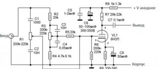
The device diagram is shown in Figure 2. A thermistor with negative TKS (thermistor) R1 is used as a temperature sensor, which together with resistor R2 forms a voltage divider. The voltage from the divider - proportional to the temperature - is supplied to the Schmitt trigger on transistors VT1, VT2. When the input voltage increases, the trigger turns on, and the field-effect transistor VT3 (closed in the initial state) opens and supplies voltage to the fan motor M1. Since a powerful zener diode VD1 is connected in series with the motor, the voltage on the fan is less than the supply voltage by the amount of the zener diode stabilization voltage. The fan runs at low speed. With a further increase in temperature, the divider voltage also increases, and at a certain value, transistor VT4 opens. This transistor bypasses the VT3-VD1 chain, and the voltage on the fan increases. Since a “vertical” transistor is used as VT4, the range of input voltages at which VT4 goes from a closed state to an open state is small and the fan speed increases to the maximum with a slight change in temperature.
Rice. 2.
Capacitor C1 forces the fan motor to start when it is turned on at a reduced voltage. This allows the fan to reliably start even when it is worn out and dusty, when the friction torque on the shaft is increased, which increases the reliability of the cooling system. Capacitor C2 reduces voltage ripple on the fan when regulating the voltage. If the device is powered from a separate independent source, then C2 can be excluded.
Trimmer resistors R3 and R9 set the operating thresholds of the cooling stages. The HL1 LED is an indicator, and its brightness indicates the voltage on the fan, and, consequently, the temperature. If you want to get more information, the display unit can be complicated by using, for example, two LEDs with different glow colors.
If it is necessary to control the temperature of several radiators, then you can use several thermistors of the same type connected in parallel (proportionally reducing the resistance R2). At the same time, due to the nonlinearity of the temperature characteristic, the system will respond to a greater extent to the hottest object, which will increase the reliability of the device as a whole.
The circuit can be powered from a lower voltage source, but this will reduce the maximum cooling efficiency.
Construction and details.
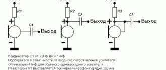
Bipolar transistors - any low-power ones with an h21E coefficient of at least 150, for example, KT3102 (I used imported BC546V). Field effect transistors - any medium power. Of the domestic ones, KP740-KP743 are suitable. Low-power KP505A-V can also be used, but the fan current in this case should not exceed 150 mA. Almost all imported transistors of the IRF5xx and IRF 6xx series are suitable. The zener diode VD1 must withstand the fan current, which at a reduced supply voltage is 40...50% of the nominal (which is about 50...150 mA). The stabilization voltage is selected so that the voltage on the engine is 5...6 volts (i.e. 6...10 volts). At a lower voltage, not all fans operate stably; a higher voltage will increase the noise level. If you cannot find a suitable zener diode, you can use its analogue (Fig. 3).
Rice. 3.
The wide variety of thermistors does not allow us to specify any specific type. Almost everything in the resistance range 1...68 kOhm will do. If the thermistor resistance exceeds 20 kOhm, then when selecting R2, its shunting with resistors R3 and R9 should be taken into account.
Since the main thing for the amplifier is passive cooling, you should use “convection” (ordinary) radiators with sparse thick fins. Fan – a suitably sized case fan from the computer. It is not recommended to use processor fans, despite their higher air flow - they are noisier. The thermistor must be installed so that good thermal contact is ensured with the radiator (using thermal paste), and it is not exposed to air flow from the fan.
Since the temperature inside the amplifier case can reach 40...50 degrees, it is possible to install an additional fan that blows air out of the case. All fans are switched on in parallel.
The device is assembled on a printed circuit board measuring 55x30 mm. I consider it inappropriate to achieve even greater miniaturization using SMD components - since relatively large-sized elements are used - radiators, then there is free space for a fan control device in the amplifier. The printed circuit board is shown in Fig. 4 (view from the installation side of the parts). The powerful zener diode VD1 is shown in red, and its analogue on a low-power zener diode and transistor is shown in light green. It's either one or the other.
Rice. 4.
Insulated conductors soldered on the side of the tracks are indicated in blue:
Rice. 5.
Setting up the device is necessary due to the wide variety of thermistors. It comes down to selecting resistor R2 and setting response thresholds for resistors R3, R9. To do this, set the switching temperatures of the device stages (in Fig. 1 these are 40 and 50 degrees) and determine the resistance of the thermistor at these two temperatures. The easiest way to determine resistance is to place the thermistor in a glass of water at the required temperature. Let's say we get the values R1_1 and R1_2. Resistor R2 must have such a resistance that the divider voltage when the first stage is turned on is about 2.5 volts:
After setting R2 to the appropriate value, instead of the thermistor, connect a variable resistor with a set resistance equal to R1_1 and, using R3, turn on the fan (the moment of switching on is adjusted; to turn off the fan, due to hysteresis, it is necessary to turn off the “thermistor”). Similarly, with the help of R9, they achieve an increase in the voltage on the fan when connecting instead of a resistance thermistor with a value equal to R1_2.
Attention!
Sometimes there is a problem like this:
“The first cooling stage is set normally. The second one is not configurable. At the extreme point of trimmer resistor R9, the voltage on the fan reaches only 3.3 V (with the first stage disabled by trimmer R3).”
Most likely, the reason is the strong difference in the parameters of thermistors of different types: for some, as the temperature increases, the resistance drops very much, and for others, not very much. As the temperature rises, the resistance of the thermistor decreases, and the voltage at the connection point R1, R2, R3 increases. When the voltage at this point reaches the triggering threshold of one of the stages, the stage is triggered and turned on. To trigger the Schmitt trigger, approximately 2.5 volts are required, and to open the field-effect transistor VT4 - about 4...5 volts (see typical transfer characteristic of the IRF630 transistor in Fig. 6). If the resistance of the thermistor does not drop much, then the voltage at the gate of the field-effect transistor does not reach the required value, and it does not open.
In this case, the adjustment must be carried out “the other way around”: select resistor R2 such that the second control stage operates reliably. To do this, R3 is brought to a minimum (the engine is in the lower position according to the diagram), and R9 is brought to a maximum (the engine is in the upper position according to the diagram). Instead of a thermistor, connect a resistor with a resistance equal to the resistance of the thermistor at maximum temperature and select R2 so that the voltage on the fan is maximum - approximately equal to the supply voltage (you can control the voltage at the connection point R1, R2, R3, it should be about 4...5 volts ). The R2 value is rounded to the nearest higher value. After this, potentiometer R3 sets the required response threshold of the first stage. Please note that capacitor C1 creates a slight time delay, so let the voltage settle for about 1...2 seconds.
It would be good to look at the reference data of the field-effect transistor before assembling the circuit - it should open (drain current approximately 100 mA) at a gate voltage of at least 3 and no more than 6 volts:
Rice. 6.
Here is a photo of the prototype (with a transistor instead of a powerful zener diode). In fact, the fee can be reduced. I'll probably do it someday...
Rice. 7.
In fact, the system can be simplified by using a specialized temperature sensor and a microcontroller (or a specialized chip), but IMHO it will not be so accessible to a wide range of radio amateurs.
Download the board in Sprint Layout 4.0 format
ventilator
01.09.2009
Total Page Visits: 2587 — Today Page Visits: 2
Low noise thermally controlled fan for bass amplifier
Recently it was necessary to force the removal of heated air from the amplifier housing. The free space on the back wall made it possible to install computer fans with external dimensions of 70x70 and 80x80 mm, but it was confusing that it was necessary to somehow reduce the noise they created. At first I took the simple route - I tried to power the motor through a resistor, but it turned out that if the fan starts steadily when turned on, it makes noise during operation. And if you make it so that it is not audible, it will start every other time. Out of more than two dozen tested, only one satisfied all the conditions, but “one” is “no ice”, it can fail in six months and then you will still have to “invent” something. I also wanted to experiment with large-capacity capacitors, soldering them in parallel with the resistor, so that when the power is turned on, additional current would flow through the capacitors and help the engine start, but then the thought occurred to me that it would be nice to also make a temperature-dependent adjustment of the fan speed. Those. While the air in the housing is cold, the hood operates at minimum speed, and as the temperature rises, the engine speed increases and, accordingly, speeds up air exchange. Well, since additional parts for control still appear, then why not also make a forced mode for starting the engine and further automatically support its minimum rotation speed (for this you can use a fan with three leads).
The debugging prototype, assembled “over-the-air” on a table, worked immediately and didn’t even have to configure anything. The operating principle of the circuit is to convert pulses coming from the fan into the fan supply voltage, but with an inverse relationship, i.e. the higher the rotation speed, the lower the supply voltage. It turns out that if you do not take into account the temperature dependence condition, the fan will always spin at one, preset speed, regardless of the supply voltage of the entire circuit. When using a temperature sensor in a circuit, this “preset speed” is forcibly changed. Here the relationship is direct - the higher the temperature, the higher the speed.
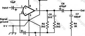
The final circuit is shown in Figure 1 . The black output from the fan is the “minus” power supply, the red one is the “plus” power supply, and the yellow one is the signal output. To receive signals from it relative to ground, it is pulled up to the positive supply by resistor R1. Pulses from it (upper graph in Figure 2 ) pass through resistor R2 and are limited in amplitude by diodes VD1...VD4 at a level of about 1.7...1.8 V (lower graph in Figure 2 ). The limitation is made so that this level does not change very much when the supply voltage changes. Next, the pulses pass through the differential circuit C1R3 ( Fig. 3 ) and are rectified by diodes VD5VD6 and filtered by capacitor C2. Differentiation is necessary so that a dependence of the level of the detected voltage on the pulse repetition rate appears. The load for C2 is resistor R4 and the input resistance of transistor VT1. When the potential at C2 reaches the opening level of transistor VT1, the voltage at its collector, and, accordingly, at the output of the composite emitter follower VT2VT3, decreases to such a level that a change in the pulse repetition rate causes a decrease in the voltage at C2 and locking of VT1. We can say that the circuit self-balances and reaches a certain stable mode.
Fig.1
Fig.2
Fig.3
In the collector load of transistor VT1 there is a thermistor with a negative temperature coefficient of resistance, this allows the circuit to obtain a thermal dependence of the fan rotation speed on the ambient temperature.
Figure 4 shows the change in the fan supply voltage level when the circuit is turned on and the temperature sensor continues to heat and cool. On the graph, the moment of switching on occurs at approximately the 2nd second. Since capacitor C2 is not yet charged, a high-level voltage appears at the output of the emitter follower VT2VT3, equal to the supply voltage of the circuit minus 1-2 volts (drop across resistors R5, R6 and base-emitter junctions of transistors). The engine starts at high speed. After about 1 second, capacitor C2 is charged, transistor VT1 opens slightly, the voltage at the emitter VT3 decreases and is then maintained at the same level. At the 9th second I begin to forcibly heat the temperature sensor (by blowing hot air from a hot air gun from a distance of 8-10 cm). Its resistance decreases, the voltage at the collector VT1 begins to increase. At the output of the repeater, accordingly, too. Then the voltage increase stops - the thermistor has stopped changing its resistance. At about the 22nd second, the blowing of hot air stops and the output voltage begins to gradually decrease. At the 34th second, the device’s power is turned off, the fan spins for another 2-3 seconds (while the capacitors are discharged) and stops.
Fig.4
Various three-wire fans were tested in the work ( Fig. 5 ). All of them were controlled normally, but almost always required adjustment of the resistance of resistor R4 to set the initial minimum engine speed. Therefore, for parallel operation of two or more fans, it is advisable to choose them of the same brand. Although this option was also tested - one three-wire fan (control pulses were taken from it) and two two-wire ones - everything was also regulated normally.
Fig.5
To indicate an emergency condition of stopping the engine, a chain of an LED, a resistor and a zener diode can be connected in parallel with capacitor C5 as shown in Figure 6 . Then, if the receipt of pulses from the fan stops, the voltage at C5 will exceed the opening threshold of the zener diode and the LED will begin to light (it, of course, will need to be brought to the front panel of the amplifier). The resistance of the resistor R is calculated based on the supply voltage of the circuit, the stabilization voltage of the zener diode and the brand of the LED. For example, with a 15 V power supply, using a KS170A zener diode and an AL307A LED, the resistor resistance can be about 680 Ohms. Then the current flowing through the circuit will be no more than 10 mA, which does not exceed the maximum current through the zener diode and is enough for the LED to glow reliably, and the voltage at which it just starts to light up will be about 8 V.
Fig.6
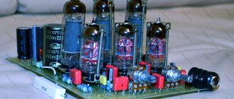
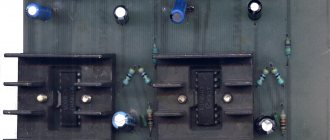
Now on to the design and the parts used. I didn’t draw and “iron” the printed circuit board for myself, but quickly cut “squares” on a piece of foil fiberglass and soldered the parts to them from above, without drilling ( Fig. 7 ). The dimensions of the board turned out to be 30x75 mm. If you do not indicate an engine stop, the length can be reduced by 5-10 mm (on the right side).
Fig.7
All parts used are ordinary output parts. Input and output connectors are pin, for example, PLS2 and PLS3. The board shows holes in the places where they are installed, but you can not drill them, but simply solder the pins to the foil, bending the lower part of the pins at an angle of 90 degrees.
Resistors – MLT 0.25. The values of R1 and R2 can be reduced by 2-3 times, and R3 can be increased, or even removed completely. The resistance of resistor R4 can also be decreased or increased, or even completely removed. A thermocouple from a computer motherboard, located under some processors, was used as a temperature sensor ( Fig. 8 ). You can use a thermistor from computer switching power supplies ( Fig. 9 ). The limits of resistance changes are approximately the same.
Fig.8
Fig.9
If thermal control is not needed, you can omit the connector for the thermistor, close the pads on the board with a drop of solder, and increase the resistance of resistor R6 to 5-10 kOhm.
All diodes are silicon KD521, KD522, or suitable imported ones - for example, 1N4148.
Capacitors C1 and C4 - any film or ceramic. Capacitance C1 affects the operation of the VD5VD6 detector, so using a different value may require changing the resistance of resistor R3 (and possibly R4). Electrolytic capacitors C2, C3 and C5 are of any brand, but it is still better to choose C2 with minimal leakage current, for example from the K-52 and K-53 series. Capacities C3 and C5 can be either halved or increased tenfold - they are simply power supply filters, but from the point of view of reducing interference in the supply circuits, it is better to increase their ratings. If C5 is not installed, then large short-term voltage pulses appear in the fan power supply, and then the signals arriving along the yellow wire of the fan have the same large pulse at the leading edge, which ultimately affects the level of the rectified voltage at C2. The circuit, of course, will work without these capacitors, but it will “radiate” with all the incoming and outgoing wires.
Transistor VT1 - KT3102 or another suitable one, but with a static current transfer coefficient of more than 200...300. If this is not the case, then you can install KT315. But then, most likely, you will need to increase the capacitance of capacitor C2 to 100...200 μF. Transistors VT2 and VT3 (KT315 and KT817) form one composite transistor - they can be replaced with similar ones (for example, KT3102 and KT815) or one with a transmission coefficient of more than 500 and with a collector current of more than 500 mA - for example, KT972. Depending on the supply voltage and current consumption of the fan used, the transistor may require a small radiator - a copper or aluminum plate measuring about 2x3 cm.
Just in case, I installed a “signet” for installation using SMD resistors and capacitors ( Fig. 10 ). The dimensions of the board turned out to be 40x40 mm and, of course, they can be further reduced by using all the parts in SMD design. The figure shows a view of the board from the printing and parts side, i.e. When using the “laser-ironing method”, the design must be “mirrored”.
Fig.10
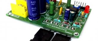
Figure 11 shows a photo of the board of the first option, already built into the amplifier. During the checks, it turned out that the temperature sensor does not need to be mounted near the radiators, but rather soldered its leads to the connector pins on the board. When the amplifier cover is closed, the fan (visible on the left) exhausts warm air, in exchange for which cold air enters through the holes in the front panel (on the right, not visible in the photo). The operation of the fans is inaudible even without their preliminary selection.
Fig.11
The state graphs presented in the text were taken using the SpectraPLUS program and a sound card with open inputs with different dividers at the input, so the scale divisions do not correspond to the real values of the measured potentials.
Attached are board layout files made in the Sprint-Layout 5 program.
Andrey Goltsov, r9o-11, Iskitim, February 2015
List of radioelements
| Designation | Type | Denomination | Quantity | Note | Shop | My notepad |
| VT1 | Bipolar transistor | KT3102 | 1 | Search in the Otron store | To notepad | |
| VT2 | Bipolar transistor | KT315A | 1 | Search in the Otron store | To notepad | |
| VT3 | Bipolar transistor | KT817A | 1 | Search in the Otron store | To notepad | |
| VD1-VD6 | Diode | KD521A | 6 | Search in the Otron store | To notepad | |
| C1 | Capacitor | 470 nF | 1 | Search in the Otron store | To notepad | |
| C2 | Electrolytic capacitor | 47 µF | 1 | Search in the Otron store | To notepad | |
| C3, C5 | Electrolytic capacitor | 100 µF 25V | 2 | Search in the Otron store | To notepad | |
| C4 | Capacitor | 100 nF | 1 | Search in the Otron store | To notepad | |
| R1, R2 | Resistor | 10 kOhm | 2 | MLT-0.25 | Search in the Otron store | To notepad |
| R3 | Resistor | 100 kOhm | 1 | MLT-0.25 | Search in the Otron store | To notepad |
| R4 | Trimmer resistor | 1 MOhm | 1 | Search in the Otron store | To notepad | |
| R5 | Thermistor | 10 kOhm | 1 | Search in the Otron store | To notepad | |
| R6 | Resistor | 1 kOhm | 1 | MLT-0.25 | Search in the Otron store | To notepad |
| Add all | ||||||
Attached files:
- Low-noise thermally controlled fan PCB files.rar (18 KB)
Tags:
- FAN
- Sprint-Layout
GENERAL PROVISIONS ABOUT INDEPENDENT ASSEMBLY OF POWER AMPLIFIERS ALL CALCULATIONS ARE SIMPLIFIED AND THE RESULTS OF CALCULATIONS DIFFER FROM THE CORRECT RESULTS IN THE SIDE OF RESERVE BY NO MORE THAN 15%
ANOTHER HYSTERICAL ABOUT MY AMPLIFIER BURNED! WAS THE REASON FOR THE CREATION OF THIS PAGE
START
ABOUT RADIATORS
The heat sink (radiator) for a power amplifier plays an important role in its operational characteristics, determining, first of all, the reliability of the amplifier and, as a rule, having its own characteristics. The main ones can be called a couple: - thermal resistance - cooling area. Without going into deep physics, the thermal resistance of a radiator is the rate at which the heating point will transfer its heat to the cooling surfaces - the fins. This parameter is taken into account quite rarely, which is why homemade amplifiers often fail. Figure 18 schematically shows the heating processes of the heat sink from the flange of the power transistor.
Figure 18 Heat distribution inside the load-bearing base of the heat sink.
When the thickness of the supporting base is 3 mm, the heat from the flange quickly reaches the back side and then spreads rather slowly, since the thickness of the material is too small. As a result, quite a lot of local heating occurs, and the cooling planes (fins) remain cold. With a supporting base thickness of 8 mm, the heat from the flange reaches the back side of the radiator much more slowly, since it is necessary to warm up sections of the radiator in the horizontal plane. In this way, heating occurs more evenly and the cooling planes begin to warm up more evenly. We could, of course, dig up a bunch of formulas and post them here, but this is too “heavy” mathematics, so we will dwell only on the approximate results of the calculations. The thickness of the supporting base of the radiator for AB amplifiers should be 1 mm for every 10 W
amplifier output power, but not less than 2 mm. For powers above 100 W, the thickness of the supporting base must be at least 9 mm + 1 mm for every 50 W exceeding 100 W. For power amplifiers with multi-level power supply (G and H), the thickness of the supporting base should be calculated in a similar way, but the amplifier power divided by the number of power levels should be taken as the initial power.
| AMPLIFIER POWER | SUPPORT THICKNESS | HOW CALCULATED | |
| CLASS AB | 10 W | 2 mm | MINIMUM |
| 40 W | 4 mm | 40 W / 10 = 4 mm | |
| 60 W | 6 mm | 40 W / 10 = 6 mm | |
| 150 W | 10 mm | 150 W - 100 W = 50 W exceeding the 100 W limit, therefore 9 mm + 1 mm = 10 mm | |
| 300 W | 13 mm | 300 W - 100 W = 200 W exceeding the 100 W limit, therefore 9 mm + (200 / 50) = 9 mm + 4 mm = 13 mm | |
| 600 W | 19 mm | 600 W - 100 W = 500 W exceeding the 100 W limit, therefore 9 mm + (500 / 50) = 9 mm + 10 mm = 19 mm | |
| 900 W | 25 mm | 900 W - 100 W = 800 W exceeding the 100 W limit, therefore 9 mm + (800 / 50) = 9 mm + 16 mm = 25 mm | |
| CLASS G OR H POWER LEVEL 2 | 500 W | 13 mm | 500 / 2 = 250 W - maximum power released by one level, 250 - 100 = 150 - the difference between the base 100 W, 150 / 50 = 3 - additional thickness to the base 9 mm, 9 +3 = 12 mm thickness of the supporting base of the radiator. |
| 1000 W | 17 mm | 1000 / 2 = 500, 500 - 100 = 400, 400 / 50 = 8, 9 + 8 = 17 mm | |
| 2000 W | 27 mm | 2000 / = 1000, 1000- 100 = 900, 900 / 50 = 18, 9 + 18 = 27 mm |
The stepwise nature of calculations for powers above 100 W is due to the fact that such amplifiers already use several transistors connected in parallel, which dissipate heat evenly in different places of the supporting base of the radiator. For classes G and H, the power is divided by 2 because it is precisely due to the changing supply voltage (connection of the second level) that the released power decreases, which is dissipated only when the signal level reaches a certain value. The cooling area is calculated purely mathematically by measuring the main dimensions of the radiator - Figure 19
Figure 20 Calculation of the cooling area of the heat sink
In this formula: a - the thickness of the load-bearing base, doubles, since it has contact with the cooling medium (air in this case) on both sides; b and d - essentially the height of the fin, both sides are used, since both have contact with the cooling medium; c - The width of the apex of the rib can be neglected; d is the distance between the radiator fins; e is the length of the back side of the radiator; n is the number of fins on the radiator; h is the height of the radiator. Fastening projections and additional ebbs can also be counted, but as a rule their area is negligible in relation to the main one, so it can be neglected. This formula also does not take into account the area of the ends of the ribs.
The radiator area is calculated based on the power of the amplifier and omitting the formula can be determined from the table:
| AMPLIFIER POWER, W | RADIATOR AREA UNDER GOOD COOLING CONDITIONS, sq cm RADIATORS ARE OUTSIDE THE CASE, THE RINS ARE POSITIONED VERTICALLY | RADIATOR AREA UNDER BAD COOLING CONDITIONS, sq cm RADIATORS INSIDE THE CASE OR IS THIS A CAR AMPLIFIER | |
| CLASS AB | 10 | 18 | 25 |
| 25 | 110 | 160 | |
| 50 | 440 | 625 | |
| 75 | 1000 | 1400 | |
| 100 | 1750 | 2500 | |
| 150 | 3900 | 5600 | |
| 200 | 6950 | 10000 | |
| 300 | 15600 | 22500 | |
| 400 | 27800 | 40000 | |
| 500 | 43400 | 62500 | |
| 600 | 62500 | 90000 | |
| 700 | 85100 | 122500 | |
| 800 | 110000 | 160000 | |
| 900 | 140500 | 200000 | |
| 1000 | 173500 | 250000 | |
| CLASS G | 500 | 13000 | 15600 |
| 1000 | 51500 | 62500 | |
| 1500 | 116000 | 140600 | |
| 2000 | 210000 | 250000 | |
| 2500 | 325000 | 390000 | |
| CLASS H | 500 | 15600 | 21600 |
| 1000 | 62500 | 86500 | |
| 1500 | 140600 | 195000 | |
| 2000 | 250000 | 35000 | |
| 2500 | 390000 | 54000 | |
You shouldn’t be afraid of huge cooling areas, since an aluminum sheet 10 x 10 cm and 0.5 cm thick has a total cooling area of 10 x 10 = 100 sq. cm, two sides, therefore 100 x 2 = 200 sq. cm, plus 4 end sides with an area 0.5 x 10 = 5 adds another 20 sq cm and as a result we get 200 + 20 = 220 cm, and the radiator shown in Figure 27 (dimensions 17 x 5.5 x 11.5 cm) has a cooling area of 3900 sq cm, so Moreover, the calculations include heating the radiator up to 80 degrees when playing the hardest compositions. You should immediately answer the question WHY FOR CLASSES G
and
H
THE AREA OF THE RADIATORS IS ALMOST TWO TIMES SMALLER AND WHY IS IT SMALLER ON
G
THAN ON
H
? To get a more understandable answer, it’s worth returning to the series of Figures 7-13 and re-reading it again - the maximum power is dissipated only at the moments the output signal passes an amplitude value equal to half the supply voltage, at other moments it either increases or decreases. When powered by two levels, the dissipated power increases until it reaches half the power supply of the first “floor”, then decreases and, having reached a value almost equal to the power supply of the first “floor”, again begins to increase to a maximum, since the second power floor (class H) is turned on stepwise, and it 2 times larger than the first “floor”. However, after the second “floor” is turned on, the power decreases as the output signal increases. Consequently, in one half-cycle of a sinusoidal signal, the final transistors will dissipate the maximum power twice, but it will exceed the value compared to class AB by only a few percent. For class G, the heating processes are somewhat different from H, since the connection of the second “floor” of power does not occur in steps, but smoothly and the dissipated power of the terminal transistors is distributed, although not evenly - the third “floor” has a heavier load than the first. Until the amplitude of the output signal has reached the turn-on value of the second floor, the terminal transistors operate in normal mode, and when the second floor is switched on, they dissipate power, but not significantly, since as a rule, the expected difference between the first and second floor is 15-18 V. when the transistors of the second floor are turned on, it is they who dissipate the greatest power, and this happens at the moment they are turned on, and as the amplitude of the output signal increases, the dissipated power decreases. In other words, the cooling area of the amplifiers G is less than H precisely due to the fact that heat release occurs in different places of the radiator - while the first floor is working, some transistors heat up, as soon as the second floor turns on they begin to cool, and other transistors located in another heat up radiator location. If there is no radiator with a suitable cooling area, then you can use forced cooling by installing fans from computer equipment on the radiators (Figure 21).
Figure 21 Appearance of computer fans
When purchasing fans, you should pay attention to the inscriptions on their stickers. In addition to the manufacturer, the fans indicate the voltage and current consumption, which determines the performance of the fan. In Figure 22, on the left is a silent low-speed motor (current 0.08A), which is almost inaudible, but which also produces a rather weak cooling flow, and on the right is a humming wind blower (current consumption 0.3A). It is recommended to use high-performance fans for power amplifiers, since the performance can always be reduced by reducing the rotation speed (reducing the supply voltage), but it is not always possible to increase it, or, more precisely, very rarely. Several fan control options can be viewed here.
Figure 22 On the left is low-performance silent, on the right is high-performance humming.
When choosing a fan, in addition to performance, you should decide on the dimensions, since there are already quite a lot of sizes on the market, and the MTBF is different for everyone, since some manufacturers use plain bearings (the impeller shaft rotates in powder bronze liners), and some use ball bearings , which of course work much longer and are less susceptible to clogging with dust. There may be several options for airflow; for example, let’s look at the two most popular ones. The first option, which is essentially widely used in computer technology, is when the fan is installed on the side of the fins, and the air flow is directed just between the cooling fins (Figure 23).
Figure 23 Installing the fan on the radiator fin side
Less popular among computer equipment, but quite popular among industrial equipment, is the pipe method. In this option, two radiators are turned with their fins facing each other, and the air flow is directed between the fins by a fan located at the end of the radiators (Figure 24).
Figure 24 Assembling a wind tunnel from two identical radiators.
This option is somewhat preferable for audio equipment, since one fan can “blow through” a fairly long radiator; if you place npn structure transistors on one radiator, and pnp structures on the other, you can do without electrically insulating gaskets, which will reduce the thermal resistance between the transistor body and the radiator. Of course, the radiators will need to be isolated from the housing, and this method is acceptable for amplifiers that use emitter followers as the output stage. By the way, the processor radiators used in computers are designed for forced cooling, and despite the fact that they have fairly large cooling areas, use without fans is not advisable. The fact is that the distance between the radiator fins is VERY small and natural air circulation is difficult, as a result of which the heat transfer drops by almost 2.5...3 times. Using a fan with a current consumption of 0.13A, one radiator from the P-IV processor can cope with the heat from two STONECOLD amplifiers installed on it with an output power of 140 W each. Summarizing all of the above, we can draw the following conclusions: - when choosing a radiator, you should pay attention not only to the cooling area, but also to the thickness of the supporting base; - power amplifiers with two-level power supply heat up almost 2 times less than class AB amplifiers at the same output powers; -if there is insufficient cooling area, it is powerful to use forced cooling (fans) with adjustable performance.
ABOUT TRANSISTORS ON RADIATORS
Even if the transistors are chosen correctly and the area of the radiator is correctly calculated, one more problem remains - correctly installing the transistors on the radiator. First of all, you should pay attention to the surface of the radiator where transistors or microcircuits are installed - there should be no extra holes there, the surface should be smooth and not covered with paint. If the surface of the radiator is covered with paint, it must be removed with sandpaper, and as the paint is removed, the grain of the paper should decrease and when there are no traces of paint left, it is necessary to polish the surface for some time with fine sandpaper. It is quite convenient to use special attachments for a cutting machine (grinder) as a sandpaper holder, or use a grinder. Possible attachment options are shown in the figures.
Figure 25 This disc is good to use for removing old paint, leveling the surface of the radiator in places where “unnecessary ribs” were removed, and “rough” grinding. During processing, a radiator is required
secure in a vice of a suitable size.
Figure 26 This attachment is good for “finishing” grinding, but using a cutting machine is not advisable - aluminum “sticks” in the sandpaper and it is very difficult to hold the machine in your hands - you can get injured. The shape of the nozzle itself fits quite comfortably in the hand and manual sanding does not cause any inconvenience, and if you screw a screw into the nozzle and wrap it with electrical tape, the work will be a joy.
If it is necessary to remove only part of the radiator fins, a cut-off wheel is made to the supporting base, then cuts are made to the fins at the base with a small-diameter cutting wheel and the “extra” fragments are broken off. After this, securing the radiator in a vice, using either a large file or a grinding wheel (it differs from a cutting wheel in being much thicker), level the break points of the ribs with the surface of the supporting base. Then the grinding tool is prepared. To make it, a wooden beam with a flat surface is used. The width of the beam should be slightly less than the width of the removed ribs, and the height should be approximately 2 times the height of the removed ribs - this will make it more convenient to hold in your hand). Then strips of rubber are glued onto both “working” sides of the timber (you can buy a rubber bandage at a pharmacy or a piece of an inner tube at a vulcanization booth). The rubber should not be stretched, the glue used is intended for rubber or has a polyurethane base. Then coarse-grained sandpaper is glued to one side of the beam for rough sanding, and fine-grained sandpaper for “finishing” is glued to the other. This creates a double-sided grinding device that allows you to quickly grind the surface of the radiator without much effort. If you use sandpaper on a paper basis, sold in car dealerships, you will need a little more of it - it is forgotten more intensively than that sold in hardware stores (on a rag basis), however, in auto stores there is a much larger selection of grain sizes - ranging from fairly coarse grains to grinding "zero".
Figure 27
The radiator from the “ancient” telephone exchange is prepared for installing two amplifiers on the TDA7293. The length of the radiator is 170 mm, the cooling area is 4650 sq. cm - the calculated value for a total power of 150 W (2 x 75) is 3900 sq. cm.
Quite often it is necessary to attach transistors to radiators through insulating gaskets. Cutting mica is not a problem, but misunderstandings often arise with insulated fasteners. The housings of transistors TO-126, TO-247, TO-3PBL (TO-264) are structurally designed in such a way that insulated fasteners are not needed - there will be no electrical contact with the flange inside the housing, in the mounting hole. But the TO-220, TO-204AA housings cannot do without insulated fasteners. You can get out of this situation by making such fasteners yourself, using ordinary screws and washers (Figure 28-a). Threads are wound around the screw near the head (preferably cotton, but finding them today is quite difficult). The winding length should not exceed 3.5 mm, the increase in diameter should not be more than 3.7 mm (Figure 28-b). Next, the threads are impregnated with SUPERGLUE, preferably SECOND or SUPERMOMENT. The threads should be wetted carefully so that the glue does not get on the adjacent thread. While the glue dries, it is necessary to make a “conductor” - a device that will allow you to normalize the height of the insulating liner located inside the transistor flange. To do this, it is necessary to drill a hole in a plastic, aluminum or textolite part (the thickness of the workpiece is at least 3 mm, the maximum is not important, but it makes no sense to take more than 5 mm), preferably on a drilling machine (so the angle relative to the plane of the workpiece will be exactly 90° , which is not unimportant), with a diameter of 2.5 mm. Then a recess with a diameter of 4.2 mm is drilled to a depth of 1.2...1.3 mm; it is advisable to drill the recesses by hand so as not to overdo it with the depth. Then an M3 thread is cut into the 2.5 mm hole (Figure 28-c).
Figure 28
Then a washer is put on the screw and it is twisted into the “jig” until the glued threads stop inside the recess, the washer is placed on the plane of the workpiece and SUPER GLUE is applied with the tip to the contact points between the screw and the washer along the entire perimeter of the contact (Fig. 29-a). As soon as the glue dries, threads are wound onto the resulting groove, moistened with SUPERGLUE from time to time until the threads are aligned with the diameter of the screw head. Ideally, the thread near the washer should be slightly larger, i.e. the resulting plastic liner will have the shape of a truncated cone (Figure 29-b). As soon as the glue dries, and this will require about 10 minutes (the glue dries more slowly inside the winding), you can unscrew the screw (Figure 29-c) and install the transistor on the radiator (Figure 30), not forgetting to treat the transistor flange and the installation location on the radiator with thermal conductive paste, for example KPT-8. By the way, several sites for overclocking IBM processors conducted tests on the thermal conductivity of various thermal pastes - KPT-8 consistently appears in second place everywhere, and taking into account the fact that it costs several times less than the winners, it turns out to be a leader in the price-quality ratio.
Figure 29
Figure 30 Fastening the TO-220 transistor using a homemade insulating screw.
The housings of TIA TO-247 transistors can be installed on the radiator using the holes available in them, and insulating fasteners are not needed, however, when assembling high-power amplifiers, drilling and tapping threads in a thick load-bearing base is quite tedious - with four pairs of ends, you need to prepare 8 holes and that’s only amplifier 400-500 watts. Moreover, silumin, duralumin, and even more so aluminum, even when drilling, stick to the cutting edge, which leads to breakage of the drill, but it’s better not to mention how many taps are broken when cutting threads. Therefore, sometimes it is easier to use additional strips that will press ALL transistors of the same structure at once, and use thicker screws as fasteners and much less of them will be required. One of the fastening options is shown in Figure 31. As can be seen from the photo, 6 transistors are pressed with only three screws and force much more if each of them were pressed with its own screw. In case of repair (God forbid, of course) it will be much easier to unscrew.
Figure 31 Attaching transistors to the radiator using a strip.
The meaning of the clamping force is that when tightening a self-tapping screw for metal (used for fastening sheet metal, sold in all hardware stores, it is better to remove the rubber from the washer immediately - it will break anyway), the strip rests on one side against the M3 screw with spacers from M4 screws. The total height of this structure turns out to be slightly greater than the thickness of the transistor housing, literally by 0.3...0.8 mm, which leads to a slight skew of the bar and with its second edge it presses the transistor in the middle of the housing. Therefore, when choosing a strip, its width should be chosen based on the following calculation: - from the edge to the middle of the hole with an M3 screw 3-4 mm - from the middle of the hole with an M3 screw to the middle of the hole with a self-tapping screw 6-7 mm - from the middle of the hole for the screw to the edge transistor 1-2 mm - from the edge of the transistor to the middle of its body ±2 mm. The width of the strip in mm is not indicated intentionally, since transistors can be mounted in almost any package in this way. The bar can be made from fiberglass, strips of which are usually lying around among radio amateurs. With a textolite thickness of 1.5 mm, to fasten TO-220 enclosures, the textolite must be folded in three, when attaching TO-247 enclosures - in four, when attaching TO-3PBL enclosures - in five. Textolite is cleaned of foil if it is foil-coated, either mechanically or by etching. Then it is sanded with the coarsest sandpaper and glued with epoxy glue, preferably made in Dzerzhinsk. After the surfaces have been sanded and coated with glue, the strips are folded and placed under a press or clamped in a vice, taking into account that excess glue will still drip somewhere, it is better to protect the place of possible drops by putting a plastic bag there, which can then be thrown away. The glue must polymerize for at least 24 hours at room temperature; it is not worth accelerating polymerization by increasing the drill bit - the glue becomes brittle, but heating, on the contrary, reduces the hardening time of the glue without changing the physical properties of the glue. You can warm it up with a regular hairdryer if you don’t have a drying cabinet. It is advisable to give the plank additional rigidity on one side by vertically folding additional strips of textolite into two. After the epoxy glue has dried, in the place of mechanical contact of the strip with the transistor body, it is necessary to stick a strip of landscape paper folded into three or four (the width of the resulting strip is 5-8 mm, depending on the transistor body), having previously coated the entire workpiece with polyurethane glue (TOP-TOP, MOMENT-CRYSTAL). This paper layer will provide the elasticity necessary for uniform pressing without reducing the effort of pressing the case against the radiator (Figure 32). As a material for the clamping bar, not only fiberglass can be used, but also a corner or a duralumin profile or other sufficiently strong material.
Figure 32
A little technological advice - despite the fact that the self-tapping screws have the shape of a drill and when fastening sheet iron do not require drilling when drilling a radiator, in the places where the self-tapping screw is screwed in, it is better to drill holes with a diameter of 3 mm, since the thickness of aluminum is much greater than the material for which these self-tapping screws are designed and aluminum sticks quite strongly to the cutting edge (you can simply twist the head when trying to screw a self-tapping screw into aluminum or silumin without drilling). The use of mounting strips can also be done when installing “different-caliber” transistors on the radiator using small thickenings of the strip at the points of contact with thinner cases, and given the fact that transistors are thinner and usually heat up less, the lack of thickness can be compensated for by laying them in several layers double-sided foam rubber tape. Now we hope that homemade power amplifiers will die much less often...
The page was prepared based on materials from a HUGE number of sites about heating engineering, audio engineering, sites about overclocking computer processors and cooling methods, through measurements and comparisons of factory versions of power amplifiers, messages and correspondence from visitors to the SOLDERING IRON and A LITTLE AUDIO EQUIPMENT forums were used.
Site administration address