In order to reduce intermodulation distortion during sound reproduction, the loudspeakers of Hi-Fi systems are composed of low-frequency, mid-frequency and high-frequency dynamic heads. They are connected to the amplifier outputs through crossover filters, which are combinations of LC low-pass and high-pass filters.
Below is a method for calculating a three-band crossover filter using the most common scheme.
The frequency response of the crossover filter of a three-way loudspeaker is shown in general form in Fig. 1. Here: N is the relative voltage level on the voice coils of the heads: fN and fB are the lower and upper limit frequencies of the band reproduced by the loudspeaker; fр1 and fр2 are crossover frequencies.
Rice. 1. Frequency response of a three-band separation acoustic filter in general form
Ideally, the output power at the crossover frequencies should be distributed equally between the two heads. This condition is met if, at the crossover frequency, the relative voltage level supplied to the corresponding head decreases by 3 dB compared to the level in the middle part of its operating frequency band.
Crossover frequencies should be chosen outside the area of greatest sensitivity of the ear (1–3 kHz). If this condition is not met, due to the difference in the phases of the oscillations emitted by the two heads at the interface frequency simultaneously, a “split” sound may be noticeable. The first crossover frequency usually lies in the frequency range 400–800 Hz, and the second – 4–6 kHz. In this case, the low-frequency head will reproduce frequencies in the fN–fp1 range, the mid-frequency head in the fp1–fр2 range, and the high-frequency head in the fр2–fB range.
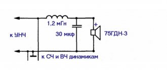
One of the common filter options for three-band acoustics is shown in Fig. 2. Here: B1 is a low-frequency dynamic head connected to the amplifier output through a low-pass filter L1C1; B2 is a mid-frequency head connected to the amplifier output through a bandpass filter formed by high-pass filters C2L3 and low-pass filters L2C3. The signal is fed to the high-frequency head B3 through high-pass filters C2L3 and C4L4.
Rice. 2. A common version of the circuit diagram of a three-band acoustics filter
The capacitances of capacitors and inductances of coils are calculated based on the nominal resistance of the loudspeaker heads. Since the nominal resistances of the heads and the nominal capacitances of the capacitors form a series of discrete values, and the crossover frequencies can vary within wide limits, it is convenient to carry out the calculation in this sequence.
Having specified the nominal resistance of the heads, select the capacitances of the capacitors from a number of nominal capacitances (or the total capacitance of several capacitors from this row) such that the resulting crossover frequency falls within the frequency intervals indicated above.
| Capacitor type | Capacity, µF |
| MBM | 0,6 |
| MBGO, MVGP | 1; 2; 4; 10 |
| MBGP | 15; 26 |
| MBGO | 20; 30 |
The capacitances of filter capacitors C1–C4 for various head resistances and the corresponding crossover frequencies are given in Table 2.
| Zg,0m | 4.0 | 4.5 | 5.0 | 6.5 | 8.0 | 12,5 | 15 |
| C1, C2, uf | 40 | 30 | 30 | 20 | 20 | 15 | |
| fp1, Hz | 700 | 840 | 790 | 580 | 700 | — | 520 |
| C3, C4, uf | 5 | 5 | 4 | 4 | 3 | 2 | 1,5 |
| fр2,kHz | 5,8 | 5,2 | 5 | 4,4 | 4,8 | 4,6 | 5,4 |
It is easy to see that all capacitance values can either be directly taken from the nominal series of capacitances. or obtained by parallel connection of no more than two capacitors (see Table 1).
After the capacitor capacitances are selected, the inductance of the coils in millihenries is determined using the formulas:
L1 = L3 = 225 Zr / fp1
L2 = L4 = 225 Zr/fp2
In both formulas: Zg—in ohms; fp1, fр2—in hertz.
Since the impedance of the head is a frequency-dependent quantity, the nominal resistance Zg indicated in the head’s passport is usually taken for calculation; it corresponds to the minimum value of the impedance of the head in the frequency range above the main resonance frequency to the upper limit frequency of the operating band.
It should be borne in mind that the actual nominal resistance of different head samples of the same type may differ from the rated value by ±20%.
In some cases, radio amateurs have to use existing dynamic heads with a nominal impedance that differs from the nominal impedances of the low-frequency and high-frequency heads as high-frequency heads.
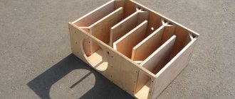
In this case, resistance matching is carried out by connecting high-frequency head B3 and capacitor C4 to different terminals of coil L4 (Fig. 2), i.e., this filter coil simultaneously plays the role of a matching autotransformer. The coils can be wound on round wooden, plastic or cardboard frames with getinax cheeks.
The lower cheek should be made square; This makes it convenient to attach it to the base - the getinax board, on which capacitors and coils are mounted. The board is secured with screws to the bottom of the speaker box. To avoid additional nonlinear distortions, the coils must be made without cores made of magnetic materials.
Loudspeakers, part 6 11/28/2017 14:09
Almost all modern high-quality speaker systems are multi-band, that is, consisting of several loudspeakers, each of which operates in its own frequency range. This is due to the fact that it is practically impossible to create a dynamic loudspeaker that would provide radiation in a wide range of frequencies with a low level of distortion (primarily intermodulation, as well as transient, nonlinear, etc.) and a wide directivity characteristic. Therefore, in acoustic systems (both professional and household) several loudspeakers are used (low-frequency, mid-frequency, high-frequency, sometimes super-high-frequency), and electrical isolation filters are included to distribute the energy of the sound signal between them.
The influence of crossover filters on the formation of the characteristics of acoustic systems was underestimated in previous years: they were assigned only the role of attenuating the signal outside the operating frequency band of the loudspeakers. However, the development of technology for Hi-Fi loudspeaker systems has forced us to reconsider the role of crossover filters in loudspeaker systems and the methodology for their design. Numerous theoretical and experimental works devoted to the influence of crossover filters on the correction of the characteristics of emitters and the formation of objective and subjective characteristics of acoustic systems have led us to consider crossover filters as one of the most important components of acoustic systems, with the help of which it is possible to synthesize many of the necessary electroacoustic characteristics and achieve significant progress in ensuring naturalness sound.
Before moving on to the analysis of various types of filters used in acoustic systems and methods for their calculation, let us dwell on determining the basic parameters of filters.
Filter parameters A filter is a device that transmits certain spectral components in a signal and does not transmit (attenuates) the rest. The filter can be implemented as an analog circuit (passive and active filters), or implemented in software or as a digital device (digital filters).
Modern speaker systems use both passive and active filters (crossovers). The first ones are turned on after the common amplifier in each channel, the second ones are turned on before the amplifier. The general connection diagram is shown in Fig. 1. Active filters have a number of advantages over passive filters, since they are much easier to tune, can be implemented in various ways, there are no power losses, etc. However, active filters are inferior to passive filters in such parameters as dynamic range, nonlinear distortion, noise level, etc. Methods for designing active filters are widely covered in specialized literature, so here we will focus only on methods for designing passive filters, which are widely used in modern acoustic systems.
The main parameters that determine the properties of filters are: - passband - the frequency range in which the filters pass the signal; - stopband - frequency region where filters significantly suppress the signal; - cutoff frequency f cf - frequency at which the signal is attenuated by 3 dB relative to the average level in the passband.
Based on the nature of the arrangement of the passband and stopband, filters are divided into four main types.
Low-pass filters (LPF) pass low-frequency components in the signal spectrum (from zero to the cutoff frequency) and suppress high-frequency ones. Used for low-frequency loudspeakers. The shape of the frequency response is shown in Fig. 2.
High-pass filters (HPF) pass high-frequency components (from the cutoff frequency and above) and suppress low-frequency ones. Used for high-frequency loudspeakers. The shape of the frequency response is shown in Fig. 2.
Bandpass filters (BPFs) pass certain frequency bands (from f cf1 to f cf2) and suppress low and high frequencies. Used for mid-frequency loudspeakers, fig. 2.
There are also notch filters, which are a combination of low-pass and high-pass filters. They suppress the spectral components of the signal in a certain frequency band and transmit in other bands. They are sometimes used in acoustic systems to cut out individual peaks and dips in the frequency response.
In addition, each of the listed filters is characterized by the following parameters: the slope of the frequency response during the transition from the passband to the stopband, unevenness in the passband and stopband, resonant frequency and quality factor (Q). Depending on the structure of the filter and the number of elements in it, different slopes of the frequency response decline can be provided. Typically, acoustic systems use filters with slopes of 12 dB/oct, 18 dB/oct and 24 dB/oct (Fig. 3), which are called second-, third-, and fourth-order filters, respectively.
The simplest structure of a second-order LC low-pass filter is shown in Fig. 4. It includes the following elements: inductance L, whose reactance is directly proportional to frequency (XL = 2πfL), and capacitance C, whose reactance is inversely proportional to frequency (XC = 1/2πfC). Therefore, shown in Fig. 4a the circuit passes low frequencies (since the inductive resistance L is small at low frequencies) and provides attenuation of high frequencies. The high-pass filter has an inverse structure (Fig. 4b) and, accordingly, passes high frequencies and delays low ones.
The type of frequency response of second-order high-pass filters for different values of quality factor is shown in Fig. 5. The resonant frequency of such a filter is defined as f=1/(LC)1/2, and the quality factor as Q = [(R2C)/L]1/2.
From Fig. 5 it can be seen that changes in the value of the quality factor changes the nature of the decline in the frequency response from smooth (at Q = 0.707) to a decline with an increase at the resonance frequency (Q = 1).
Based on the names of the scientists who mathematically described the transfer functions of filters (that is, their shapes of frequency characteristics), they received different names: filters with a quality factor Q = 1 are called Chebyshev filters, Q = 0.707 - Butterworth, Q = 0.58 - Bessel, Q = 0.49 - Linkwitz-Riehle. Each of these types of filters has its own advantages and disadvantages.
Active three-band filter based on NM2116
Yuri Sadikov, Moscow
The article presents the results of work on creating a device that is a set of active filters for building high-quality three-band low-frequency amplifiers of the HiFi and HiEnd classes.
In the process of preliminary studies of the total frequency response of a three-band amplifier built using three second-order active filters, it turned out that this characteristic has a very high unevenness at any filter junction frequencies. At the same time, it is very critical to the accuracy of filter settings. Even with a small mismatch, the unevenness of the total frequency response can be 10...15 dB!
MASTER KIT produces a set NM2116, from which you can assemble a set of filters, built on the basis of two filters and a subtractive adder, which does not have the above disadvantages. The developed device is insensitive to the parameters of the cutoff frequencies of individual filters and at the same time provides a highly linear total frequency response.
The main elements of modern high-quality sound reproducing equipment are acoustic systems (AS).
The simplest and cheapest are single-way speakers that contain one loudspeaker. Such acoustic systems are not capable of operating with high quality in a wide frequency range due to the use of a single loudspeaker (loudspeaker head - GG). When reproducing different frequencies, different requirements are placed on the GG. At low frequencies (LF), the speaker must have a large and rigid cone, a low resonant frequency and have a long stroke (to pump a large volume of air). And at high frequencies (HF), on the contrary, you need a small, lightweight but solid diffuser with a small stroke. It is almost impossible to combine all these characteristics in one loudspeaker (despite numerous attempts), so a single loudspeaker has high frequency unevenness. In addition, in wideband loudspeakers there is an intermodulation effect, which manifests itself in the modulation of high-frequency components of an audio signal by low-frequency ones. As a result, the sound picture is disrupted. The traditional solution to this problem is to divide the reproduced frequency range into subranges and build acoustic systems based on several speakers for each selected frequency subrange.
Passive and active electrical isolation filters
To reduce the level of intermodulation distortion, electrical isolation filters are installed in front of the loudspeakers. These filters also perform the function of distributing the energy of the audio signal between the GG. They are designed for a specific crossover frequency, beyond which the filter provides a selected amount of attenuation, expressed in decibels per octave. The slope of the attenuation of the separating filter depends on the design of its construction. The first order filter provides an attenuation of 6 dB/oct, the second order - 12 dB/oct, and the third order - 18 dB/oct. Most often, second-order filters are used in speakers. Filters of higher orders are rarely used in speakers due to the complex implementation of the exact values of the elements and the lack of need to have higher attenuation slopes.
The filter separation frequency depends on the parameters of the GG used and on the properties of hearing. The best choice of crossover frequency is one at which each GG speaker operates within the piston action area of the diffuser. However, in this case, the speaker must have many crossover frequencies (respectively, GG), which significantly increases its cost. It is technically justified that for high-quality sound reproduction it is enough to use three-band frequency separation. However, in practice there are 4, 5 and even 6-way speaker systems. The first (low) crossover frequency is selected in the range of 200...400 Hz, and the second (middle) crossover frequency in the range of 2500...4000 Hz.
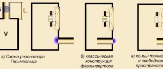
Traditionally, filters are made using passive L, C, R elements, and are installed directly at the output of the final power amplifier (PA) in the speaker housing, according to Fig. 1.
Fig.1. Traditional performance of speakers.
However, this design has a number of disadvantages. Firstly, to ensure the required cutoff frequencies, you have to work with fairly large inductances, since two conditions must be met simultaneously - to provide the required cutoff frequency and to ensure that the filter is matched with the GG (in other words, it is impossible to reduce the inductance by increasing the capacitance included in the filter). It is advisable to wind inductors on frames without the use of ferromagnets due to the significant nonlinearity of their magnetization curve. Accordingly, air inductors are quite bulky. In addition, there is a winding error, which does not allow for an accurately calculated cutoff frequency.
The wire used to wind the coils has a finite ohmic resistance, which in turn leads to a decrease in the efficiency of the system as a whole and the conversion of part of the useful power of the PA into heat. This is especially noticeable in car amplifiers, where the supply voltage is limited to 12 V. Therefore, to build car stereo systems, GGs with reduced winding resistance (~2...4 Ohms) are often used. In such a system, the introduction of additional filter resistance of the order of 0.5 Ohm can lead to a decrease in output power by 30%...40%.
When designing a high-quality power amplifier, they try to minimize its output impedance to increase the degree of damping of the GG. The use of passive filters significantly reduces the degree of damping of the GG, since additional filter reactance is connected in series with the amplifier output. For the listener, this manifests itself in the appearance of “booming” bass.
An effective solution is to use not passive, but active electronic filters, which do not have all the listed disadvantages. Unlike passive filters, active filters are installed before the PA as shown in Fig. 2.
Fig.2. Construction of a sound-reproducing path using active filters.
Active filters are RC filters on operational amplifiers (op amps). It is easy to build active audio filters of any order and with any cutoff frequency. Such filters are calculated using tabular coefficients with a pre-selected filter type, required order and cutoff frequency.
The use of modern electronic components makes it possible to produce filters with minimal intrinsic noise levels, low power consumption, dimensions and ease of execution/replication. As a result, the use of active filters leads to an increase in the degree of damping of the GG, reduces power losses, reduces distortion and increases the efficiency of the sound reproduction path as a whole.
The disadvantages of this architecture include the need to use several power amplifiers and several pairs of wires to connect speaker systems. However, this is not critical at this time. The level of modern technology has significantly reduced the price and size of the mind. In addition, quite a lot of powerful integrated amplifiers with excellent characteristics have appeared, even for professional use. Today, there are a number of ICs with several PAs in one case (Panasonic produces the RCN311W64A-P IC with 6 power amplifiers specifically for building three-way stereo systems). In addition, the PA can be placed inside the speakers and short, large-section wires can be used to connect the speakers, and the input signal can be supplied via a thin shielded cable. However, even if it is not possible to install the PA inside the speakers, the use of multi-core connecting cables does not pose a difficult problem.
Modeling and selection of the optimal structure of active filters
When constructing a block of active filters, it was decided to use a structure consisting of a high-pass filter (HPF), a medium-frequency filter (band-pass filter, PSF) and a low-pass filter (LPF).
This circuit solution was practically implemented. A block of active filters LF, HF and PF was built. A three-channel adder was chosen as a model of a three-way speaker, providing summation of frequency components, according to Fig. 3.
Fig.3. Model of a three-channel speaker with a set of active filters and a filter filter on the PF.
When measuring the frequency response of such a system, with optimally selected cutoff frequencies, it was expected to obtain a linear dependence. But the results were far from expected. At the junction points of the filter characteristics, dips/overshoots were observed depending on the ratio of the cutoff frequencies of neighboring filters. As a result, by selecting the cutoff frequency values, it was not possible to bring the pass-through frequency response of the system to a linear form. The nonlinearity of the pass-through characteristic indicates the presence of frequency distortions in the reproduced musical arrangement. The results of the experiment are presented in Fig. 4, Fig. 5 and Fig. 6. Fig. 4 illustrates the pairing of a low-pass filter and a high-pass filter at a standard level of 0.707. As can be seen from the figure, at the junction point the resulting frequency response (shown in red) has a significant dip. When expanding the characteristics, the depth and width of the gap increases, respectively. Fig. 5 illustrates the pairing of a low-pass filter and a high-pass filter at a level of 0.93 (shift in the frequency characteristics of the filters). This dependence illustrates the minimum achievable unevenness of the pass-through frequency response by selecting the cutoff frequencies of the filters. As can be seen from the figure, the dependence is clearly not linear. In this case, the cutoff frequencies of the filters can be considered optimal for a given system. With a further shift in the frequency characteristics of the filters (matching at a level of 0.97), an overshoot appears in the pass-through frequency response at the junction point of the filter characteristics. A similar situation is shown in Fig. 6.
Fig.4. Low-pass frequency response (black), high-pass frequency response (black) and pass-through frequency response (red), matching at level 0.707.
Fig.5. Low-pass frequency response (black), high-pass frequency response (black) and pass-through frequency response (red), matching at level 0.93.
Fig.6. Low-pass frequency response (black), high-pass frequency response (black) and pass-through frequency response (red), matching at the level of 0.97 and the appearance of an overshoot.
The main reason for the nonlinearity of the pass-through frequency response is the presence of phase distortions at the boundaries of the filter cutoff frequencies.
A similar problem can be solved by constructing a mid-frequency filter not in the form of a bandpass filter, but using a subtractive adder on an op-amp. The characteristics of such a PSF are formed in accordance with the formula: Usch = Uin – Uns – Uss
The structure of such a system is shown in Fig. 7.
Fig.7. Model of a three-channel speaker with a set of active filters and a PSF on a subtractive adder.
With this method of forming a mid-frequency channel, there is no need to fine-tune adjacent filter cutoff frequencies, because The mid-frequency signal is formed by subtracting the high- and low-pass filter signals from the total signal. In addition to providing complementary frequency responses, the filters also produce complementary phase responses, which guarantees the absence of emissions and dips in the total frequency response of the entire system.
The frequency response of the mid-frequency section with cutoff frequencies Fav1 = 300 Hz and Fav2 = 3000 Hz is shown in Fig. 8. According to the fall in the frequency response, an attenuation of no more than 6 dB/oct is ensured, which, as practice shows, is quite sufficient for the practical implementation of the PSF and obtaining high-quality sound of the midrange GG.
Fig.8. Frequency response of the mid-pass filter.
The pass-through transmission coefficient of such a system with a low-pass filter, a high-pass filter and a high-pass filter on a subtracting adder turns out to be linear over the entire frequency range of 20 Hz...20 kHz, according to Fig. 9. Amplitude and phase distortions are completely absent, which ensures crystal purity of the reproduced sound signal.
Fig.9. Frequency response of a filter system with a frequency filter on a subtractive adder.
The disadvantages of such a solution include strict requirements for the accuracy of the values of resistors R1, R2, R3 (according to Fig. 10, which shows the electrical circuit of the subtracting adder) that ensure balancing of the adder. These resistors should be used within 1% accuracy tolerances. However, if problems arise with the acquisition of such resistors, you will need to balance the adder using trimming resistors instead of R1, R2.
Balancing the adder is performed using the following method. First, a low-frequency oscillation with a frequency much lower than the low-pass filter cutoff frequency, for example 100 Hz, must be applied to the input of the filter system. By changing the value of R1, it is necessary to set the minimum signal level at the output of the adder. Then an oscillation with a frequency obviously higher than the high-pass filter cutoff frequency, for example 15 kHz, is applied to the input of the filter system. By changing the value of R2, the minimum signal level at the output of the adder is again set. The setup is complete.
Fig. 10. Subtractive adder circuit.
Methodology for calculating active low-pass filters and high-pass filters
Radio amateurs themselves can calculate the low-pass filter and high-pass filter at the required cutoff frequency using the following calculations.
As theory shows, to filter the frequencies of the audio range, it is necessary to use Butterworth filters of no more than the second or third order, ensuring minimal unevenness in the passband.
The second-order low-pass filter circuit is shown in Fig. 11. Its calculation is made according to the formula:
where a1=1.4142 and b1=1.0 are tabular coefficients, and C1 and C2 are selected from the ratio C2/C1 greater than 4xb1/a12, and you should not choose the ratio C2/C1 much greater than the right side of the inequality.
Fig. 11. 2nd order Butterworth low pass filter circuit.
The second-order high-pass filter circuit is shown in Fig. 12. Its calculation is made using the formulas:
where C=C1=C2 (set before calculation), and a1=1.4142 and b1=1.0 are the same table coefficients.
Fig. 12. 2nd order Butterworth high-pass filter circuit.
MASTER KIT specialists have developed and studied the characteristics of such a filter unit, which has maximum functionality and minimal dimensions, which is essential when using the device in everyday life. The use of modern element base made it possible to ensure maximum quality of development.
Technical characteristics of the filter unit
| Supply voltage, V | 12…30 |
| Current consumption, mA | 10 |
| Low-pass filter Gain in passband, dB Attenuation out of passband, dB/oct Cutoff frequency, Hz | 0 12 300 |
| HF filter Gain in passband, dB Attenuation out of passband, dB/oct Cutoff frequency, Hz | 0 12 3000 |
| Mid-pass filter (bandpass) Gain in passband, dB Attenuation out of passband, dB/oct Cutoff frequencies, Hz | 0 6 300, 3000 |
| PCB dimensions, mm | 61×42 |
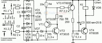
The electrical circuit diagram of the active filter is shown in Fig. 13. The list of filter elements is given in the table.
The filter is made using four operational amplifiers. The op-amps are combined in one MC3403 (DA2) IC package. DA1 (LM78L09) contains a supply voltage stabilizer with corresponding filter capacitors: C1, C3 at the input and C4 at the output. An artificial midpoint is made on the resistive divider R2, R3 and capacitor C5.
The DA2.1 op amp has a buffer cascade for pairing the output and input impedances of the signal source and low-pass, high-pass and mid-range filters. A low-pass filter is assembled on op-amp DA2.2, and a high-pass filter is assembled on op-amp DA2.3. Op-amp DA2.4 performs the function of a bandpass midrange filter shaper.
The supply voltage is supplied to contacts X3 and X4, and the input signal is supplied to contacts X1, X2. The filtered output signal for the low-frequency path is removed from contacts X5, X9; with X6, X8 – HF and with X7, X10 – MF paths, respectively.
Fig. 13. Electrical circuit diagram of an active three-band filter
List of elements of an active three-band filter
| Position | Name | Note | Col. |
| C1, C4 | 0.1 µF | Designation 104 | 2 |
| C2, C10, C11, C12, C13, C14, C15 | 0.47 µF | Designation 474 | 7 |
| C3, C5 | 220 µF/16 V | Replacement 220 uF/25 V | 2 |
| C6, C8 | 1000 pF | Designation 102 | 2 |
| C7 | 22 nF | Designation 223 | 1 |
| C9 | 10 nF | Designation 103 | 1 |
| DA1 | 78L09 | 1 | |
| DA1 | MC3403 | Replacement LM324, LM2902 | 1 |
| R1…R3 | 10 kOhm | 3 | |
| R8…R12 | 10 kOhm | Tolerance no more than 1%* | 5 |
| R4…R6 | 39 kOhm | 3 | |
| R7 | 75 kOhm | — | 1 |
| DIP-14 block | 1 | ||
| Pin connector | 2 pin | 2 | |
| Pin connector | 3 pin | 2 |
The appearance of the filter is shown in Fig. 14, the printed circuit board is shown in Fig. 15, the location of the elements is shown in Fig. 16.
Structurally, the filter is made on a printed circuit board made of foil fiberglass. The design provides for installation of the board into a standard BOX-Z24A case; for this purpose, mounting holes are provided along the edges of the board with a diameter of 4 and 8 mm. The board is secured in the case with two self-tapping screws.
Fig. 14. External view of the active filter.
Fig. 15. Active filter printed circuit board.
Fig. 16. Arrangement of elements on the active filter printed circuit board.
The material was published in the journal Radioschema 2007`06.
BM2115
Active low pass filter for subwoofer
990
NM0103
Low pass filter for subwoofer (LPF) - soldering kit
790
TRANSMISSION FUNCTION
The transfer function of a filter is understood as the ratio of the complex voltage amplitude at the filter output to the complex voltage amplitude at the input. Typically, transfer functions of physically realizable and stable linear circuits are described in the form of mathematical formulas, the denominators of which are expressions of the following form (polynomials): Gn(s) = ansn+a n-1sn-1+…….+a1s+1. The order of the filter is determined by the power n of the complex frequency s, which is related to the ordinary circular frequency as s = jω. (the quantity j is called the imaginary unit). The choice of the type of coefficients an determines whether the filters belong to the Butterworth, Chebyshev, etc. type. For example, Butterworth polynomials of different orders have the form B1 (s) = (1+s); B2 (s) = (1+1.414s+s2), etc.
In acoustic systems, the problem of choosing filters is complicated by the fact that it is necessary to select three or two (depending on the number of bands) types of filters of the same or different orders, which, together with loudspeakers, would provide the overall characteristics of the acoustic system (such as amplitude-frequency response, phase-frequency characteristic - phase response, group delay time - group delay, etc.) with the required parameters within an effectively reproducible frequency range.
History of the creation of filters The history of the creation of crossover filters begins simultaneously with the advent of multi-band speaker systems. One of the first theories was developed in the 30s by engineers G. A. Campbell and O. J. Zobel from Bell Labs (USA). The first publications date back to the same period, their authors K. Hilliard and H. Kimball worked in the sound department of Metro Goldwin Meyer. In 1936, their article “Loudspeaker Isolation Filters” was published in the March 1936 issue of the Academy Research Council Technical Bulletin. In January 1941, K. Hilliard also published “Loudspeaker Isolation Filters” in Electronics Magazine, which contained all the necessary formulas for creating first- and third-order Butterworth circuits (for both parallel and series circuits). By the 1950s, Butterworth filters were recognized as the filter of choice for speaker separation purposes. At the same time, in the 60s, JR Ashley and R. Small first described the properties of “all-passing” filter circuits, as well as linear-phase circuits.
The article “Filter Circuits and Modulation Distortion” (by R. Small), published in JAES in 1971, was devoted to elucidating the quantitative relationship between the attenuation introduced by out-of-band filters and the amount of intermodulation distortion due to overlapping speaker bands. It showed that the minimum attenuation value should be 12 dB/oct to prevent distortion in the overlap band. At the same time, Ashley and L. M. Henne investigated the “all-passing” and “phase coherent” properties of third-order Butterworth filters. In 1976, S. Linkwitz studied the polar radiation pattern for two-way systems with spaced drivers and was convinced that speaker systems with Linkwitz-Riehle crossover filters ensure its symmetry.
A little later, P. Garde gave a complete description of all-pass filters and their varieties. Using his ideas, D. Fink, in collaboration with E. Long, developed a method for correcting horizontal (that is, depth) displacement of loudspeaker heads in acoustic systems by introducing delay lines into the filter. Significant contributions to the theory of filtration were made by W. Marshall-Leach and R. Bullock, who first introduced the concept of optimizing filters by type and order, taking into account the displacement of heads along two axes. In continuation of these works, R. Bullock described the properties of three-band symmetrical filters and proved that a three-band filter system cannot be obtained as a simple combination of two-band ones, contrary to popular belief. S. Lipshitz and J. Vanderkooy, in a series of articles, examined various options for constructing filters with minimal phase characteristics.
A new stage in the research and design of multiband acoustic systems with crossover filters began with the beginning of active computerization of calculations based on the programs HORT, CACD, CALSOB, Filter Designer, LEAP 4.0, etc.
Until recently, the design of crossover filters in acoustic systems was carried out practically by trial and error. This is explained by the fact that all theoretical works of past years devoted to the calculation of crossover filters in acoustic systems were based on the condition that the loudspeakers themselves were ideal. When analyzing the properties of crossover filters of one type or another and considering their influence on the characteristics of speaker systems, the directional properties of loudspeakers and the conditions of their physical placement in the speaker system housing were neglected. It was believed that loudspeakers have a flat frequency response, do not introduce phase shifts into the reproduced signal, and have an active input impedance. As a result of the above, developers often encountered the fact that crossover filters that provide the required characteristics under idealized conditions turned out to be unacceptable when working with real loudspeakers that have their own amplitude-frequency and phase-frequency distortions, complex input impedance and directional properties. This was the reason for the intensification in recent years of work on the creation of optimization methods for calculating separation filters-correctors.
Selection of crossover frequencies As already noted, crossover filters have a significant impact on such characteristics of multiband acoustic systems as frequency response, phase response, group delay, directivity characteristics, distribution of input signal power between emitters, input impedance of the speaker system, and the level of nonlinear distortion.
The initial stage in the design of crossover filters in multi-band acoustic systems is a reasonable choice of crossover frequencies (cutoff frequencies) of low-frequency, mid-frequency and high-frequency channels. When choosing crossover frequencies, the following assumptions are usually used.
1. Providing the most uniform directional characteristics possible, that is, the absence of “jumps” in the width of the radiation pattern when moving from low-frequency to mid-frequency and from mid- to high-frequency loudspeaker, since in the frequency region where they work together, in the absence of a filter, the radiation pattern is sharp narrows due to the expansion of the radiation area.
2. Maintaining a smooth change in the width of the directivity characteristic (for the same reason). We try to place the loudspeakers as close to each other as possible and place them on top of each other in the vertical plane (this avoids distortion of the directivity characteristics in the horizontal plane, as this negatively affects the reproduction of stereo panorama). If the choice of crossover frequency and distance between loudspeakers affects the width of the directivity characteristic, then the ratio of the phases and amplitudes of the signals of the separated frequency channels affects the orientation of the directivity characteristic in space. Different types of filters, as will be shown below, influence the slope of the directivity characteristic in space in the region of crossover frequencies to varying degrees.
3. Weakening of peaks and dips in the frequency response of loudspeakers that arise due to the loss of the piston nature of the movement of the diffuser. They try to select the cutoff frequency and slope of the frequency response of filters for low-frequency and mid-frequency loudspeakers in such a way that the first resonant peaks and dips are attenuated by no less than 20 dB.
4. Limiting the displacement amplitude of moving systems of mid- and high-frequency loudspeakers in the low-frequency part of the spectrum they emit (and, accordingly, the supplied power) to values determined by their mechanical and thermal strength, which increases the reliability of their operation and reduces the level of nonlinear distortions. These tasks are regulated by both the choice of cutoff frequency and the choice of cutoff slope, which must be at least 12 dB/oct.
5. Providing the required sound pressure level, since with an increase in the cutoff frequency in the high-frequency region, the level of applied voltage can be increased, for example, to a high-frequency loudspeaker (since the amplitudes of the cone displacement decrease with increasing frequency). This allows you to increase, accordingly, the sound pressure level in the high-frequency part of the frequency response.
6. Reducing the level of nonlinear distortions, in particular, due to the Doppler effect (arising when high-frequency components are modulated by low-frequency components of the signal).
As a rule, the cutoff frequencies in modern three-way speaker systems are in the range: for a low-frequency loudspeaker - 500...1000 Hz, for a mid-frequency loudspeaker - from 500...1000 Hz to 5000...7000 Hz, for a high-frequency loudspeaker - 2000...5000 Hz.
Influence on the total characteristics It is convenient to analyze the influence of separation filters on the formation of the total frequency response, phase response and other characteristics of acoustic systems on some idealized model, in which it is assumed that the loudspeakers have active resistance and ideal characteristics (flat frequency response, linear phase response, constant phase shift between the emitters and etc.). When calculating filters, you must first select the cutoff frequency (as shown earlier), the order and type of filter (Butterfort, Chebyshev, Linkwitz-Riehle, etc.).
Based on the resulting overall characteristics, filters usually used in acoustic systems can be divided into three groups: linear-phase filters (in-phase), all-pass filters and all others.
Linear-phase filters (in-phase) provide a frequency-independent total frequency response, a linear phase response (more precisely, equal to zero at all frequencies), as well as a group delay equal to zero. An example is first-order Butterworth filters. The overall characteristics for a two-way system with such filters are shown in Fig. 6. The experience of using them in acoustic systems has shown that they have a number of disadvantages: poor selectivity, large unevenness of signal power characteristics, poor directional characteristics in the interface band, etc. Therefore, they are currently not used in Hi-Fi loudspeaker systems.
All-pass filters provide a flat total frequency response, frequency-dependent phase response and group delay. The requirements for linearity of the phase response response are excessive for acoustic systems - it is enough that their group delays are below the audibility thresholds (as measurement results show, filters of this type introduce group delay distortions in the interface band that satisfy these requirements). This type of filter includes Butterworth filters of fuzzy orders and Linkwitz-Riehle filters of even orders. In this case, the properties of the filters are realized with different polarities of switching on the channels: for 2, 6, 10 orders, the switching on of channels in antiphase is required, for 4, 8, 12 - not. For odd orders: 1, 5, 9 should be switched on in phase, 3.7... - out of phase. The total and channel-by-channel characteristics of the second-order Linkwitz-Riehle and third-order Butterworth filters for a two-channel idealized acoustic system are shown in Fig. 7 and fig. 8. It should be noted (will be shown later) that fuzzy order filters create a rotation of the main lobe of the directivity characteristic in the crossover frequency region.
There is a fairly large class of filters that are used in acoustic systems, but they are not of the “all-passing” type. This includes filters of the second and fourth order of Butterworth, second and fourth order of Bessel, a group of asymmetric filters of the fourth order of Legendre, Gauss, etc. They do not give a total flat response, but this drawback can be partially corrected if the cutoff frequencies between the loudspeakers are made unequal. For example, in Fig. Figure 9a shows the characteristics of a fourth-order Butterworth filter with a frequency response peak of 3 dB at a crossover frequency of 1000 Hz. If you separate the frequencies somewhat, that is, make the crossover frequency for low frequencies 885 Hz, and for high frequencies 1138 Hz, then the peak in the frequency response disappears (Fig. 9b).
As already mentioned, the choice of filter types for low-, mid- and high-frequency loudspeakers, in addition to ensuring a flat frequency response in the crossover bands, is determined by the requirement to ensure symmetry of the directivity characteristics of the speaker system.
Within the passband of each filter, the directivity characteristic of the speaker system is determined by the directivity characteristic of each loudspeaker, but within the cutoff band (filter overlap band), they work together, that is, there are two emitters (for example, mid- and high-frequency), which are spaced apart and operate on the same the same crossover frequency. An example of such a system is shown in Fig. 10. For simplicity, let these be two identical emitters operating in piston mode with the same directivity characteristics. On the OA axis, the signals arrive in the same phase and are added. If we estimate the sound pressure on the OA' axis, where the phase shift due to the difference in path from one and the other loudspeaker is φ = π (that is, 180 degrees), then the signals will add up in antiphase and a dip will appear in the directivity characteristic. With a further shift from the axis at points where the phase difference is 2π (that is, 360 degrees), a peak will again appear. In general, the directivity characteristic will have a three-lobe character (Fig. 10).
The width of the main lobe of the directivity characteristic at the crossover frequency depends on the ratio of the distance between the loudspeakers to the wavelength, and the slope of the lobe depends on the ratio of the amplitudes and phases of the separated channels, which is also determined by the type of filters chosen.
To reduce this phenomenon, one should try to reduce the distance between loudspeakers (for example, through the use of coaxial loudspeakers), reduce the crossover bandwidth (by choosing higher-order filters) and, finally, select the appropriate filter type, since each filter contributes its own frequency-dependent phase shifts.
For example, when using third-order Butterworth-type filters, the main lobe of the directivity characteristic rotates downward (when the speakers are turned on in the same phase), Fig. 11. When the speakers are turned on in antiphase (that is, their polarity is changed), the lobe of the directivity characteristic shifts to the other side relative to the axis.
Analysis of filters of various types and orders showed that filters of even orders (all-passing type) do not change the symmetry of the direction of the lobes, filters of odd orders turn the lobe down or up. Symmetrical directivity characteristics provide the greatest uniformity of emitted acoustic power.
In addition to influencing the directivity characteristic along the frequency response, filters can affect the phase-frequency characteristics and group delays in the interface band. That is, the nature of transient processes, despite the symmetry of the frequency response, may differ at the same displacement angles in the upper and lower half-planes, and group delays, being below the audibility thresholds on the axis, can exceed the audibility thresholds at other points in space, thereby deteriorating the sound quality.
It should be recalled once again that all conclusions drawn relate only to the case of ideal loudspeaker characteristics. Real characteristics are taken into account using modern computer programs.
Calculation of passive acoustic filters When starting to calculate passive acoustic filters, it is necessary to clearly define the system configuration (number of playback bands, types of loudspeaker heads and their parameters, type of design - housing), and also select the order and type of filters depending on the main tasks that must be decided when designing an acoustic system: flat frequency response, linear phase response, symmetrical directivity characteristic, etc.
Since nowadays acoustic systems most often use “all-pass” filters with a flat frequency response, we will give an approximate calculation of this type of filter (more accurate calculations are performed using computer methods).
First, the isolation filters are calculated from the condition that they are loaded with purely active resistance and are powered by a voltage generator with low output resistance. Care is then taken to take into account the effects of complex frequency-dependent loudspeaker loading.
The calculation begins with determining the order of the filters and calculating the elements of the prototype filter. A prototype filter is a ladder-type filter, the elements of which are normalized relative to a unit cutoff frequency and a unit load. The low-pass filter is then calculated for the actual cutoff frequency and the actual load, and from this the high-pass and bandpass filter elements are found by frequency conversion.
The normalized values of the prototype filter elements from the first to the sixth order are shown in Table 1.
The values of these elements are given only for filters of the “all-passing” type; for other types of filters, the values of the elements in the table will be different. The prototype sixth-order filter circuit is shown in Fig. 12. Filters of lower orders are obtained by discarding the corresponding α elements (starting with the largest ones).
The values of real filter parameters for a given order, load resistance R n (Ohm) and cutoff frequency f i (Hz) are determined as follows.
1. For a low-pass filter: - each prototype inductance α1, α3, α5 (Fig. 12) is replaced with a real inductance according to the formula L=αi Rн/2πf1, (1) where i=1,3,5, f1 - frequency low pass filter cutoff; — each prototype capacity α2, α4, α6 is replaced with a real capacity according to the formula C=αi /2πf1Rн, (2) where i=2,4,6.
2. For a high-pass filter (the calculation is the other way around): - each prototype inductance α1, α3, α5 is replaced by a real capacitance C=1/2πf2Rнαi, (3) where i=1,3,5, f2 is the cutoff frequency of the high-pass filter frequencies; — each prototype capacitance is replaced with a real inductance L=Rн/2πf2αi, (4) where i=2,4,6.
3. For a bandpass filter: - each prototype inductance α1, α3, α5 is replaced by a series circuit of real L- and C-elements, calculated by the formulas: L=αiRн/2π(f2-f1),(5) C=1 /4π2f02L,(6) where is the average frequency of the bandpass filter; — each capacitance element α2, α4, α6 is replaced by a parallel circuit of real L- and C-elements, calculated by the formulas: C=αi/2π(f2-f1)Rн,(7) L=1/4π2f02C.(8 )
DIY speaker filters
Making a filter for a speaker is not at all difficult. It consists of only two elements - a capacitor and an inductor. The easiest way to calculate the parameters of radioelements for a second-order low-frequency passive circuit is to use an online calculator. There you can set the desired cutoff level and acoustic head resistance. The program will display the required capacitance of the capacitor and inductance of the coil. For example, the cutoff level is 150 Hz and the speaker impedance is 4 ohms. The calculator will give the following values:
- Capacitor capacity – 187 µF
- Coil inductance – 6.003 mH
The required capacity can be obtained from parallel-connected capacitors K78-34, which are specially designed for operation in acoustic systems. In addition, there is an updated line of capacitors of a similar type. This is KZKWhiteLine. As inexpensive analogues, radio amateurs often use capacitors such as MBGO or MBGP.
A 6 mH inductor coil is wound on a mandrel with a diameter of 1 cm and a length of 6 cm. Since the coil does not have a magnetic core, a cylinder of any material can be used as a bobbin, on which cheeks must be made for ease of winding. For winding, copper wire of the PEL type with a diameter of 1 mm is used. The length of the wire is 84 meters. Winding must be done turn to turn.