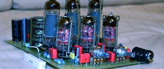
Amplifier output power indicators
Display meters
The output power indicator is a beautiful and useful thing at the same time. In modern car amplifiers they are used more and more often, even in budget models. But it’s not always possible to look at this beauty - it’s usually in the trunk, so its usefulness is, to put it mildly, questionable. It's a completely different matter if the indicator is on the instrument panel. However, so far there is only one such device in a “separate” version - McIntosh. Its dimensions are 1 DIN, the price is kind of softer... In general, it’s time to make this miracle with your own hands, having, in addition to a soldering iron, only a multimeter.
All power indicators are connected to the amplifier output. You can use either separate indicators for each channel or a general indicator of the total power of two or more channels. This display is clearer and more convenient than separate displays by channels. And if there are five or six channels, then how many eyes are needed? In any case, you should not install more than two indicators. The McIntosh six-channel amplifier has only two - one shows the power of channels one through four, the second shows the fifth and sixth, more powerful ones.
The following diagrams are extremely simplified. The flip side of this simplicity is the need to select elements when setting up. This is quite justified for “piece” production, but these circuits are of little use for mass production.
Dial indicators
Dial indicators are the simplest. Their manufacture requires a minimum of parts and qualifications, especially if you use “mixed mono”, which allows you to slightly reduce the number of parts (Fig. 1).
Fig.1
Fig.2
In Fig. Figure 2 shows a diagram of a simple indicator. If necessary, the number of channels can be increased by adding resistors and diodes, as shown in the dotted line. When using the indicator in conjunction with a radio amplifier, in series with resistors R1, R2, you need to turn on electrolytic capacitors with a capacity of 47...100 μF (“plus” to the radio). You can also use “mixed mono” (see Fig. 1), in which no capacitors are required, and the R2VD2 chain can be eliminated.
The resistance of a resistor connected in series with the device depends on the total deflection current. The approximate resistance value can be found using the formula shown in the figure. The exact value should be adjusted when setting according to the required needle deflection at a given power. The remaining parts can be used of any type. The smoothing electrolytic capacitor must be designed for an operating voltage of at least 25 volts when measuring power up to 15 W and at least 50 volts for higher power. The voltage margin is needed because the capacitor is used in the AC circuit. By selecting its capacitance within the range of 1...100 µF, you can adjust the return time of the needle to suit every taste.
The disadvantage of the circuit is its small dynamic range, not exceeding 10 dB. This is enough for a radio, but when working with a high-power amplifier, the needle will deviate only at signal peaks. In this case, it is better to use the circuit shown in Fig. 3.
Fig.3
Its main difference is the dynamic range expander on the VD1 diode and HL1 LED. As soon as the rectified voltage on capacitor C1 reaches a value of 0.7 V, the diode opens and further increase in voltage is slowed down by resistor R3. By selecting its resistance within 100 Ohm...10 kOhm, you can adjust the “travel” of the scale in the middle part. The next limitation occurs at the moment the LED lights up and further increase in voltage practically stops. The LED can be used as an overload indicator. The resistance of the input resistors is determined by the maximum power of the amplifier and the current of the applied LED. The calculation formula is shown in the figure; the exact resistance value should be adjusted based on the moment the LED lights up at maximum power.
The resistance of a resistor connected in series with the device can be found using the second formula. The exact value should be adjusted when setting according to the required deviation of the arrow at the moment the LED lights up. The voltage on the red LED is approximately 1.6 V, on the brighter yellow-orange - approximately 2.5 V. The remaining parts can be used of any type. The smoothing electrolytic capacitor must be designed for an operating voltage of 6.3 ... 10 V, since the voltage on it is limited by the LED. The indicator is connected in the same way as the previous one.
The dynamic range of such an indicator can easily be increased to 20 dB; to further expand the dynamic range, a special control circuit with a logarithmic amplifier is required, and such a circuit goes beyond the simplest.
LED indicators
The design of LED indicators is somewhat more complicated. Of course, when using a special control chip, it can be simplified to the limit, but there is a small nuisance lurking here. Most of these microcircuits develop an output current of no more than 10 mA and the brightness of the LEDs in a car may not be sufficient. In addition, the most common are microcircuits with outputs for 5 LEDs, and this is only a “minimum program”. Therefore, for our conditions, a circuit based on discrete elements is preferable; it can be expanded without much effort.
The simplest LED indicator (Fig. 4) does not contain active elements and therefore does not require power. Connection - to the radio according to the "mixed mono" scheme or with a coupling capacitor, to the amplifier - "mixed mono" or directly.
Rice. 4
The scheme is extremely simple and does not require setup. The only procedure is to select resistor R7. The diagram shows the rating for working with the built-in amplifiers of the head unit. When working with an amplifier with a power of 40...50 W, the resistance of this resistor should be 270...470 Ohms. Diodes VD1...VD7 - any silicon with a forward voltage drop of 0.7...1 V and a permissible current of at least 300 mA.
Any LEDs, but of the same type and color with an operating current of 10...15 mA. Since the LEDs are “powered” from the output stage of the amplifier, their number and operating current cannot be increased in this circuit. Therefore, you will have to choose “bright” LEDs or find a place for the indicator where it will be protected from direct lighting. Another drawback of the simplest design is the small dynamic range.
To improve performance, an indicator with a control circuit is needed. In addition to greater freedom in choosing LEDs, you can simply create a scale of any type - from linear to logarithmic, or “stretch” only one section. The diagram of an indicator with a logarithmic scale is shown in Fig. 5. The dotted line shows optional elements.
Rice. 5
The LEDs in this circuit are controlled by switches on transistors VT1...VT5. The switch thresholds are set by diodes VD3...VD9. By selecting their number, you can change the dynamic range and scale type. The overall sensitivity of the indicator is determined by the resistors at the input. The figure shows approximate response thresholds for two circuit options - with single and “dual” diodes. In the basic version, the measurement range is up to 30 W at a 4 Ohm load, with single diodes - up to 18 W.
LED HL1 lights up constantly, it indicates the beginning of the scale, HL6 is an overload indicator. Capacitor C4 delays the extinguishing of the LED by 0.3...0.5 seconds, which allows you to notice even a short-term overload. Storage capacitor C3 determines the reverse time. By the way, it depends on the number of glowing LEDs - the “column” from the maximum begins to fall quickly, and then “slows down”. Capacitors C1, C2 at the input of the device are needed only when working with the built-in amplifier of the radio. When working with a “normal” amplifier, they are excluded. The number of input signals can be increased by adding a chain of resistor and diode. The number of indication cells can be increased by simple “cloning”; the main limitation is that there must be no more than 10 “threshold” diodes and there must be at least one diode between the bases of neighboring transistors.
Any LED can be used depending on the requirements - from single LEDs to LED assemblies and high-brightness panels. Therefore, the diagram shows the values of current-limiting resistors for different operating currents. There are no special requirements for the remaining parts; transistors can be used in almost any npn structure with a collector power dissipation of at least 150 mW and a double collector current reserve. The base current transfer coefficient of these transistors must be at least 50, and better - more than 100.
This scheme can be somewhat simplified, and as a side effect new properties appear that are very useful for our purposes (Fig. 6).
Rice. 6
Unlike the previous circuit, where the transistor cells were connected in parallel, a sequential “column” connection is used here. The threshold elements are the transistors themselves and they open one by one - “from bottom to top”. But in this case, the response threshold depends on the supply voltage. The figure shows approximate thresholds for the indicator to operate at a supply voltage of 11 V (left border of the rectangles) and 15 V (right border). It can be seen that as the supply voltage increases, the maximum power indication boundary shifts the most. If you are using an amplifier whose power depends on the battery voltage (and there are many of them), such “auto-calibration” can be beneficial.
However, the price for this is an increased load on the transistors. The current of all LEDs flows through the lower transistor in the circuit, so when using indicators with a current of more than 10 mA, the transistors will also require the appropriate power. “Cloning” cells further increases the unevenness of the scale. Therefore, 6-7 cells is the limit. The purpose of the remaining elements and the requirements for them are the same as in the previous diagram.
Slightly modernizing this scheme, we obtain other properties (Fig. 7). In this scheme, unlike those previously discussed, there is no luminous “ruler”. Only one LED lights up at a time, simulating the movement of a needle along a scale. Therefore, energy consumption is minimal and low-power transistors can be used in this circuit. Otherwise, the scheme does not differ from those discussed earlier.
Threshold diodes VD1...VD6 are designed to reliably turn off idle LEDs, so if weak illumination of excess segments is observed, it is necessary to use diodes with a high forward voltage or connect two diodes in series. “Cloning” the cells reduces the brightness of the upper segments in the circuit; to eliminate this, a current generator must be introduced instead of resistor R9. And we agreed - not to complicate things. Therefore, in this case, 8 cells is the maximum.
Rice. 7
Nutrition
Indicators that consume current less than 150...200 mA can be powered from the Remote output of the head unit. The voltage there is 0.5...1 V less than in the on-board network, but this will not affect the operation of the device in any way. If the current consumed by the indicator is greater, you will have to use a low-power relay (RES-55, RES-10) or assemble an electronic relay according to the diagram in Fig. 8.
Rice. 8
And when it comes to power, it would be nice to equip the audio system with its own voltmeter. Even if it is included in the standard equipment of the car, it does not work when the ignition is turned off. In addition, he measures the voltage at some unknown point. In domestic cars, everything affects its readings - from the turned on turn signals to the flashing handbrake light. For our purposes, it is better to measure the voltage at the battery terminals or at the buffer capacitor - whichever is more convenient.
A simple pointer voltmeter is not suitable - it has a linear scale, and everything below 10-11 volts is of no interest to us. A decent head unit is blocked or “freezes” if the voltage in the on-board network drops to these limits. Therefore, the scale must be stretched so that it resembles the scale of a conventional automobile voltmeter on the instrument panel. By the way, you can use a “regular car” for this purpose, but you shouldn’t. It consumes quite a decent amount of current from the on-board network (several tens of milliamps), which is why it is turned on through the ignition switch. But we need a voltmeter that works constantly or at least independently of the ignition. The diagram of such a voltmeter is shown in Fig. 9.
Fig.9
Fig.10
A zener diode with a stabilization voltage of about 10.5...11 V provides a “stretch” of the scale; the voltmeter is calibrated with a resistor for the maximum deviation at the maximum voltage in the on-board network (14.5-16 V). The scale will have to be built point by point using an adjustable power supply and a reference voltmeter. If exact values are not required, you can limit yourself to only determining the boundaries of the “green” and “red” sectors. The current consumption is determined by the deflection current of the indicator (less than a milliampere), so the voltmeter can and should be made non-switchable - the clock consumes much more.
For an LED power indicator, the following circuit is more suitable (Fig. 10).
The principle of its operation is the same as the previous one. As long as the voltage in the on-board network is normal, the transistor is open and bypasses the LED. As soon as the voltage drops to the stabilization voltage of the zener diode, the transistor will close and the LED will flash, signaling a problem. For better visibility, you can use a “flashing” LED with a built-in control circuit. The response threshold is determined by the zener diode, so for precise tuning it will have to be selected. Unlike the previous one, this circuit consumes more current, determined by resistor R2. Although it is small (about 10 mA), it is better to power it from the Remote output, taking into account the voltage loss on it.
If you go this route further, you can also install a thermometer that measures the temperature of the amplifier (or driver). So let's leave it at that for now.
Design
When debugging designs, you can use trimming resistors, but you should not transfer them to the finished circuit - reliability may suffer, especially when using small-sized open-type potentiometers. It is better to measure the set resistance with a digital device and solder a constant resistor of the required value.
Dial indicators contain a minimum of parts, so they can be assembled by hinged mounting by gluing the parts to the body of the measuring device. The scale can be printed on a color printer (in prehistoric times it was necessary to draw it in ink and color it).
LED scales and displays are easy to use, but only allow you to get a “ruler” or “column”. If you need a broken or curved scale, it will have to be made from single LEDs. They need to be glued into the front (supporting) panel of the indicator, covered on top with a printed scale with holes, and on top of it with thin plexiglass. You can use a tight fit or glue to hold the LEDs in place.
For LED indicators, it is better to use board mounting - there are a lot of parts. Making a full-fledged printed circuit board for the sake of a single design only makes sense if you have experience, so it’s easier to use an industrial-made breadboard for assembling parts. Parts are placed on it, and connections are made with a thin mounting wire. As a last resort, you can place the parts on a sheet of thin PCB or cardboard, put the leads on the back side and connect them according to the diagram, using both the leads themselves and the mounting wire. The circuit board can be combined into one with the LED panel. After adjustment, the finished circuit should be washed from flux residues with an alcohol-gasoline mixture (take care of the plastic parts of the indicator!) and coated with varnish to protect against oxidation. If you wish, you can even pour everything into a “cube” of epoxy resin...
And finally. The indicator is not a power meter, but only a pointer. Therefore, its readings should be treated with caution, although the scale can be calibrated.
Published in the magazine “Master 12volt” No. 32 (April 2001), Author of the article: A.I. Shikhatov
Comments ()
Write a comment
How to assemble an LED level indicator on LM3915 with your own hands
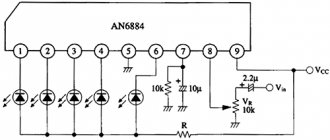
The design of the LM3915 chip consists of ten similar operational amplifier comparators housed in a housing. The direct inputs of the amplifiers are connected through a line of resistive dividers selected so that the LEDs in the amplifier load are turned on according to a logarithmic dependence. The return inputs of the amplifiers receive an input signal, which is generated by a buffer amplifier (pin 5). The design of the microcircuit also includes an integrated stabilizer (pins 3, 7, 8), as well as a key for setting the operating mode of the indicator (pin 9). The microcircuit has a wide supply voltage range from 3 to 25 Volts. The reference voltage value is set in the range from 1.2 to 12 Volts by external resistors. The indicator scale corresponds to a signal level of 30 dB in 3 dB steps. The output current is adjustable from 1 to 30 mA.
Assembly of the indicator is simplified by purchasing a set of parts in the online store at the link https: //ali.pub/2c62ph
. The kit includes a board, a microcircuit, LEDs and all the necessary wiring (resistors, capacitors and connectors).
Set of parts “Sound level indicator for LM3915”
Details of the “Sound Level Indicator for LM3915” kit
The sound indicator circuit on the LM3915 is shown in the photo.
Operating principle. A supply voltage of 12 Volts is supplied to the third pin of the LM3915. It is also supplied to the LEDs through the limiting resistor R2. Resistors R1 and R8 equalize the brightness of the red LEDs on the scale. Also, a voltage of 12 Volts is supplied to the jumper for controlling the operating mode of the indicator (pin 9). When the jumper is closed, the circuit ensures that only one LED lights up, corresponding to the signal level. When the jumper is open, the circuit operates in the “column” effect mode; the input signal level is proportional to the height of the illuminated column or the length of the line. The divider assembled on R3, R4 and R7 limits the input signal level. Fine tuning of the divider is carried out by multi-turn tuning resistance R4. Divider R9 R6 sets the offset for the upper level of the logarithmic rule of the microcircuit resistance (pin 6). The lower level of the resistance slide rule (pin 4) is connected to the common wire. Resistor R5 (pin 7) increases the reference voltage and affects the brightness of the LEDs. R5 sets the current through the LEDs and is calculated by the formula: R5=12.5/Iled, where Iled is the current of one LED, A. The sound level indicator works as follows. At the moment when the input signal overcomes the lower level threshold plus the resistance at the direct input of the first comparator, the first LED (pin 1) will light up. A further increase in the sound signal will lead to the comparators being activated one by one, which will be indicated by the corresponding LED. According to the instructions, in order to avoid damage to the microcircuit, you should not exceed the 20 mA limit for the current supplied to the LEDs.
Schematic diagram
The output signals of stereo channels from the ULF output are supplied through capacitors C1 and C2 to the inputs of elements D1.1 and D1.2, respectively. The inputs of these elements through resistors R2 and R3 receive a constant bias voltage from the trimming resistor R1.
At the inputs of logic elements, the DC offset voltage is added to the AC component of the audio signal. The task of resistor R1 is to set the optimal bias voltage at which the required sensitivity of the indicator will be, that is, this resistor sets the same peak threshold.
Rice. 1. Schematic diagram of a homemade peak indicator.
The state at the outputs of elements D1.1 and D1.2 will change only when this threshold is exceeded; the set value of this circuit is converted into logic level pulses, which charge capacitors C3 and C4 through diodes VD1 and VD2. These circuits of diodes VD1, VD2, capacitors C3, C4 and resistors R4, R6 work as detectors.
And the voltage on capacitors C3 and C4 increases. This is especially important since the peak moment of the input signal may not last long. And the voltage in the form of charge is retained by these capacitors because they are charged quickly through the diodes and discharged slowly through the resistors.
As soon as the voltage at C3 or C4 reaches the switching threshold of the Schmitt trigger (D1.3 or D1.4, respectively), a logical zero appears at the output of D1.3 or D1.4, which causes the HL1 or HL2 LED to light up. The corresponding LED, or if the stereo signal is well balanced, both LEDs flash and remain on for at least the time required to discharge C3 or C4 through R4 or R6.

