Audio amplifier repair
— As a rule, a repairman with extensive experience in the field of radio electronics begins repairing an audio power amplifier with a visual inspection of the device’s printed circuit boards in order to identify burnt or darkened electronic components. It is best to look for a failed part step by step, that is, you first need to identify a non-working cascade , and then identify the component that caused the inoperability of the amplifier. The check should begin with the output stage, during the inspection without using measuring instruments such as a multimeter yet, but simply with the power of the amplifier turned on and the input signal present, you need to touch the powerful transistors of the final stage with a dry finger or the same output microcircuit and determine the temperature of the part body.
If the output transistors are generally cold, then this indicates that there is no passing current in the circuit, which should heat these components in normal operating mode, or vice versa, if the part is heated up so that it is impossible to hold your finger on it, then this is also a consequence of a malfunction. Thus - the voltage stabilizer is also checked using the same method, in particular large-capacity electrolytic capacitors; if they get hot or there are traces of leaks and swelling, then they need to be changed, in general this applies to all electrolytes installed in the circuit. Also during a visual inspection in order to identify poor contact on printed circuit board, you need to carefully tap the board with the handle of a screwdriver, the disappearing contact will be revealed by extraneous sounds
and crackling in the speakers.
Next, you need to check the AC and DC voltage values of transistors and microcircuits with a multimeter. After finding the faulty element, it is very important to determine why this part could fail in order to eliminate such a phenomenon in the future. After these steps, you can begin replacing the component with exactly the same the same part or its equivalent. The search for defects in the power supply should be carried out by inspecting the mains cable and checking the fuses. If everything is normal here and the mains voltage supplied to the primary winding of the transformer is present, but not present on the output secondary winding, then it is possible that a fuse, which caused the lack of voltage in the secondary circuit, and if there is no fuse installed, then there is a break in the primary winding, in which case the trans will have to be rewinded or searched for a suitable one for the output voltage.
Another reason for the inoperability of the amplifier may be an ordinary short circuit of the output circuit to the housing or to the common wire. In amplifiers built on microcircuits as an output amplification stage, then if the microcircuit malfunctions, simply change it to another one that is known to be good, and if it is not possible to find a suitable one in terms of parameters then you can replace the burnt one with an ordinary low-frequency amplifier of the TDA type, which does not require tying with additional elements, so replacing any faulty power amplifier with a TDA series microcircuit will not be difficult.
A low frequency amplifier (LFA) is a device whose purpose every music lover knows. This component of the audio system allows you to improve the sound quality of the acoustics as a whole. But like any other electronic devices, the AC can fail. Learn more about how to repair car audio system amplifiers yourself in this article.
[Hide]
Typical faults
Before you repair, install and configure the ULF in your car, you need to understand the breakdown. It is simply impossible to consider all the faults that can be encountered in practice, since there are so many of them. The main task of repairing a sound amplification device is to restore a broken component, the failure of which led to the inoperability of the entire board.
In any electrical equipment, including amplifiers, there can be two types of faults:
- contact is present where it should not be;
- There is no contact in the place where there should be contact.
Functionality check
Repair of car amplifiers first begins with ULF diagnostics:
- First you need to open the case and carefully inspect the circuit, use a magnifying glass if necessary. During diagnostics, you may notice damaged components of the circuit: resistors, capacitors, broken conductors or burnt out board tracks. But if you find a burnt-out component, you need to take into account that its failure may be a consequence of the burnout of another element, which in appearance may seem intact.
- Next, diagnose the power supply, in particular, check the output voltage. If burnt out resistors are identified, these elements will need to be replaced.
- Apply power to the ULF and the Remout output, then you need to short-circuit the system to positive and look at the PROTECTION diode indicator. If the light comes on, this indicates that the device has been protected. The reason may be poor power or its absence on the board, a broken transistor, or problems with the operation of the voltage converter. In some cases, the reason lies in the breakdown of the transistor power amplifier for one of several channels.
- If, after power has been applied, the fuse element does not burn out, you need to check the voltage level at the output. It should be approximately 2x20 in or more.
- Carefully inspect the transformer device of the voltage converter; it may have burnt out turns or broken circuits. Smell this element, it may smell burnt. In some ULF models, a diode assembly is installed between the PN output and the amplifier - if it fails, the assembly can also include protection.
Scheme and testing method
The output of the amplifier under test is loaded with an active resistance equal to the rated load of 4, 8, 16 or 32 ohms and capable of dissipating the rated output power of the amplifier.
The output of the generator is connected to the linear input of the amplifier. The output level of the generator is selected so that when the amplifier volume control is partially open, a signal with an amplitude of 1-2 volts is obtained at the oscilloscope input. It is not recommended to fully open the volume control for this type of measurement to prevent saturation of the amplifier's transistor stages.
The quality of the rectangular signal, in particular its edges, is not critical, because if there is distortion introduced by the amplifier, this will be clearly visible on the oscillogram.
A rectangular signal has a frequency spectrum rich in harmonics and, to be honest, theoretically, for its ideal reproduction it is necessary that the upper limit of the amplifier’s frequency range be located somewhere at infinity, in which case the signal fronts will be perfectly rectangular.
In practice, if some frequencies are not passed at all or are passed worse, then the shape of the output signal is modified. The shape also changes if phase distortion occurs between certain frequencies or frequency bands in the spectrum, or if the amplifier introduces large nonlinear distortions, or is self-excited.
Troubleshooting
Do-it-yourself repair of a car amplifier is carried out in accordance with what problem was identified during its operation:
- If a transistor in a car amplifier breaks down, then before directly replacing it, it is recommended to diagnose the power supply safety element. You also need to make sure that the diodes on the buses are working. If everything is in order with these parts, the installed transistors need to be changed.
- For more specialized repairs, you will need an oscilloscope. By installing the device probes on pins 9 and 10 of the generator board, you need to make sure that there are signals. If there are no signals, then the driver is changed; if there are signals, then the field-effect transistor elements are replaced.
- Capacitors are changed much less frequently during the repair process - as practice shows, this happens infrequently (the author of the video is the HamRadio Tag channel).
Basic Amplifier Settings
Now let's move on to the question - how to set up a car amplifier? There are several configuration options - for use with or without a sub.
How to properly configure the ULF without a subwoofer - first you need to set the following parameters:
- bass boost - 0 decibels;
- level - 0 (8V);
- The crossover must be set to FLAT.
After this, adjusting the audio system settings with an equalizer, the system is configured to suit your preferences. The volume must be set to maximum and turn on some track. How to set it up for use with a subwoofer - the procedure is also not particularly complicated.
For proper configuration, it is advisable to use the following parameters:
- Bass Boost should also be set to 0 decibels;
- the level is set to 0;
- the front crossover is set to the HP position, and the FI PASS control element must be set in the range from 50 to 80 Hertz;
- As for the rear crossover, it is set to the LP position, and the Low control must be set in the range from 60 to 100 Hertz.
It is very important to observe these parameters, since they determine the quality of the adjustment and, accordingly, the sound of the audio system. In general, the setup procedure is similar, using a level control to ensure a more harmonious sound. The sensitivity of the rear and front speakers should be adjusted to each other.
If you don’t understand anything about this, it’s better not to go there, because repairs will cost more after you burn or break.
Sorry, there are no surveys available at this time.
Here I will share my modest experience in the field of car amplifier repair. I hope the information will be useful to novice radio mechanics in their difficult task of restoring audio equipment, as well as to car enthusiasts who are familiar with electronics and want to repair their amplifier themselves.
To begin with, I would like to talk about how to turn on a car amplifier without a car radio and at home. Read more about this. This will be needed when repairing a car amplifier.
If you don’t have a powerful enough power supply at hand, then any one with a voltage of 12V and a current of 1 - 3 amperes will do. But here it is worth understanding that we only need it to turn on and set up the amplifier. We will not operate it at full power, so the current consumption will be minimal.
I also strongly recommend reading or taking note of the material on the design of a car amplifier converter. This information is very important.
Well, now, examples of repairs from real practice. They mainly concern one of the main blocks of any car amplifier - a voltage converter, or in other words - an inverter.
Repair of car amplifiers CALCELL.
1. Malfunction: the car amplifier goes into protection.
The red PRT (Protect) LED lights up on the front panel. After a couple of turns on, the amplifier stopped showing signs of life altogether - the PRT LED stopped glowing.
The cause of the malfunction turned out to be the 2N4403 transistor in the circuit of the TL494CN chip (converter). One of his crossings was breached. In addition, a 10Ω (Ohm) resistor burned out. In the photo R7 is him. While the resistor “endured”, the amplifier turned on, but went into protection. When it burned out, the amplifier stopped turning on altogether.
Pinout of bipolar PNP transistor 2N4403.
Why did the amplifier go into protection? The fact is that this transistor is part of the on/off circuit. Due to the breakdown of the PN junction of the transistor, the amplifier did not turn on and went into protection.
There was no suitable replacement for the 2N4403 PNP transistor at hand. Therefore, a risky attempt was made to take the same transistor from the preliminary stage of one of the amplifier channels. Luckily they were there. Yes, just think, I decided, well, I’ll take the transistor out of there, solder it in place of the faulty one, and check the amplifier. Oh yes, I did just that. But after a few seconds after turning it on, I smelled a burning smell. It turned out that due to the absence of one small transistor, the powerful complementary transistors of the UMZCH output stage began to get terribly warm. Fortunately, the transistors survived. Therefore, I do not recommend being “cunning” like that.
Replacing the transistor was complicated by the fact that it was stained with some kind of rubber glue that glued the barrels of electrolytes to the board.
2. The CALCELL POP 80.4 amplifier does not turn on. Safety fuses blow.
The device arrived “dead,” apparently after an incorrect connection. After a quick inspection of the parts without soldering, it was discovered that the 11V zener diode in the “piping” of the TL494CN PWM controller chip was broken. A breakdown of the TL494CN microcircuit itself was also discovered. When measuring the resistance between pin 12 (+ power supply, V cc
) and 7 (- power supply,
GND
) the multimeter showed “0”. Apparently the amplifier supply voltage was greatly overestimated.
After replacing the TL494CN chip and the zener diode at 11V, an attempt was made to turn on the amplifier. But, after turning on, the red PRT LED lit up for a few seconds (as it should be), and then complete silence... . The power supply from which the amplifier was powered went into protection due to overcurrent.
It turned out that one of the two groups of MOSFET transistors on the converter board was getting very hot. Transistors of the other group are cold. After checking 3 STP75NF75 transistors that were heating up, it turned out that they were broken (Source - Drain). The 2N4403 transistor, which is a buffer for this converter arm, was also broken. You can familiarize yourself with the diagram of a typical car amplifier converter (inverter) in more detail.
After replacing the 2N4403 buffer transistor and three STP75NF75 MOSFETs (labeled P75NF75), the auto amplifier began to work properly.
3. Amplifier CALCELL POP 80.4.
“PROTECT”
LED lights up and goes out after a few seconds. The amplifier does not turn on - there is no indication.
This happens when the converter goes into protection due to high current consumption or a short circuit in the load. The load in this case is all four amplifiers, a filter block and preamplifiers.
The most likely reason for the protection to trip is the failure of the output transistors. The CALCELL POP 80.4 amplifier uses powerful bipolar transistors as output transistors. You can evaluate their serviceability using this method, and it is not at all necessary to unsolder the transistors. As a rule, the breakdown of the transistor junction is easily determined; the multimeter begins to beep unpleasantly with a buzzer - a signal that there is zero resistance between the terminals of the transistor.
It is worth considering that with such a quick test, parts associated with the transistor being tested (low-power transistors, etc.) can affect the readings. Therefore, if in doubt, we unsolder and check the transistor separately. It is not uncommon that it is the elements associated with our transistor that are broken, and not the transistor itself. Some amplifiers, for example, such as the SUPRA SBD-A4240, use MOSFETs as output transistors. MOSFET transistors can be checked with a universal tester, since a conventional multimeter is not always suitable for such purposes.
Let's return to our amplifier. For greater clarity, I will refer to the circuit diagram of this amplifier - CALCELL POP 80.4 auto amplifier circuit. When checking the output transistors of one of them, the Base-Collector (BC) transition “ringed” as if it had been broken. In the diagram it is designated as Q312 ( 2SA1694
).
To check the performance of the amplifier, I removed the faulty transistor and its complementary pair - transistor 2SC4467 (Q311). I turned on the amplifier, but it went into defense again. This means there is something burnt somewhere. In addition, low-power transistors Q309 ( MPSA06
) and Q310 (
MPSA56
) got very hot. The check showed that transistor Q309 (MPSA06) had both junctions broken.
Since the complementary pair 2SC4467/2SA1694 was not on sale, I decided to replace it with more powerful analogues - the pair 2SA1943/2SC5200
manufactured by TOSHIBA. Like this. They feel heavy to the touch and inspire confidence.
After installing the new 2SA1943/2SC5200 transistors, it turned out that they were too large and because of this the board did not fit into the case.
I had to bite out a small part of the printed circuit board so that they would fit into the case and fit tightly to the surface.
After replacement, the amplifier began to work properly.
During the electrical run, I noticed that even without a load, the low-power transistors in the preamplifiers heat up quite noticeably. When playing music with a lot of bass, the heating increases. The amplifier drove two subwoofers (one per bridge).
Perhaps long-term operation at maximum power led to overheating and failure of the low-power transistor MPSA06 (Q309), and this in turn to a breakdown of the B-K junction of the powerful transistor 2SA1694 (Q312) in the output stage of the amplifier.
4. Non-standard case.
A CALCELL amplifier that had just been purchased in a store was brought in for repair. According to the owner, after connecting the power, smoke came out of the amplifier's ventilation holes.
After opening and inspecting the printed circuit board, it turned out that there were traces of solder paste and solder balls on the terminals of one of the MOSFET transistors of the converter. Here is a photo.
Apparently, current flowed through the remaining solder paste when turned on. Because of this, the rosin in the paste heated up and began to evaporate in the form of a white haze. After this, the amplifier did not turn on due to a solder bridge formed when the solder paste melted. It's no secret that cheap electronics made in China do not pass pre-sale testing. Hence these “blunders”.
Repair of Lanzar VIBE 221 car amplifier.
Diagnosis: the car amplifier does not turn on.
No LED indication. Judging by the appearance of the printed circuit board, they tried to repair the amplifier, and even the key MOSFET transistors in one of the converter arms were replaced. Instead of the native IRFZ44N, STP55N06 were installed. But the amplifier died for a long time. Also in the gate circuit of the MOS transistors there were “burnt” but serviceable 100 Ohm resistors. When checking the 2SA1023 buffer transistors, which “drive” the IRFZ44N mosfets, it turned out that they were working.
After replacing the TL494CN PHI controller chip, the amplifier started working. Just in case, 2SA1023 buffer transistors and 1N4148 diodes in the base-emitter circuit of these transistors were replaced.
Mystery car amplifier repair.
Problem: The amplifier turns on, but there is no sound.
Mystery 1.300
car amplifier is a typical representative of the so-called monoblocks. That is, it is a monophonic amplifier. The sound power declared by the manufacturer is 300W. Such amplifiers are usually used to drive a powerful low-frequency speaker, that is, a subwoofer or subwoofer.
After opening and inspecting the printed circuit board, it turned out that several transistors (2SB1367 and 2SD2058) were poorly soldered, there was solder degradation and excessive heating of the solder points. The transistors appear to be part of the 15V stabilizers in the secondary power circuits. These stabilizers are used to power operational amplifiers and amplifier filters. In another way, this unit can be called a preamplifier
. It is to this that we connect the very “tulips” through which the sound signal from the car radio is sent. Naturally, if there is no power to the preamplifier, then there will be no sound.
Why did it happen? The fact is that the transistors that overheated do not have a radiator; their housing is plastic. They rely on their own conclusions. There is no additional fastening. Due to overheating and constant shaking (it was installed in a car), the soldering was destroyed and the contact was broken. Therefore, the stabilizers stopped working. Any more and the transistors would simply fall out of the mounting holes!
After restoring the soldering of the transistors, the amplifier was fully operational, but the noticeable heating of the transistors suggested that there would be a repeat after some time.
It was decided to install heating transistors on a homemade radiator to reduce heating. Also update the pin soldering and make it more reliable. This is what came out of it.
At the same time, adjacent transistors were placed on the radiator, which heated up less - to add rigidity to the structure. Since the transistors are in a plastic case and do not have a metal flange, I also applied thermal conductive paste KPT-19 to the place of thermal contact with the radiator.
Among other things, on the printed circuit board of the monoblock there was a clearly “swollen” electrolytic capacitor of 3300 µF* 63V in the secondary rectifier. The power supply - inverter usually contains 2 electrolytic capacitors, since the power supply
The amplifier stages
are bipolar
, in the region of ± 28 - 37 volts. The adjacent electrolyte looked better and was not “swelled”.
It was decided, just in case, to replace the electrolyte that had swollen with a new one at 4700 µF * 63V (this was available). During an electrical run of the car amplifier, it turned out that the replaced electrolytic capacitor was slightly heating up. It turned out that it was heated by powerful resistors located nearby. For reference, the neighboring electrolyte does not have such resistors nearby. This is an obvious flaw. As you know, heating has a bad effect on electrolytic capacitors, since the electrolyte dries out faster and their capacity decreases.
Repair of car amplifier Fusion FP-804.
Fault: the car amplifier does not turn on. No indication.
After opening it, it didn’t take long to find the cause. The converter burned out all the HFP50N06 MOSFET transistors (the original was STP50N06), as well as several 47 Ohm resistors in the gate circuit of some of these transistors. The 2SA1266 buffer transistors were also knocked out.
Instead of the burnt HFP50N06 transistors, IRFZ48N were installed, new 2SA1266 buffer transistors, burnt 47 Ohm resistors were replaced, as well as a TL494CN PHI controller chip, just in case.
The device turned on and began to work properly. But my joy was short-lived. Three days later, the owner of the amplifier called me and said that a weak monotonous whistle had appeared in the rear speakers. The whistle was only heard when the engine was running.
The first thought that came to mind was interference from the generator that gets into the audio path of the amplifier. This happens when wiring has been done hastily and the supply and signal (interblock) circuits are close together. But the electrical wiring and interconnect cables were made with high quality, which I was convinced of. A day later they brought me a “dead” Fusion FP-804 amplifier with a familiar diagnosis: it won’t turn on.
The most interesting thing was that the “Power”
glowed barely noticeably. But I didn't pay attention to this. After opening it, it turned out that the same MOSFETs were knocked out again. So this amplifier ended up in my scrap pile - they gave it away for parts.
After some time, I decided to restore this amplifier, and I wanted to figure out what was the reason for the widespread burnout of rather expensive mosfets in the converter. I bought new transistors to replace the faulty ones, installed them and...
At the first launch I witnessed an enchanting show. Immediately after switching on, I heard a growing whistle - a slow start of the converter, and then I saw sparks jumping from the center of the toroidal transformer.
Here it is - a malfunction! Breakdown of windings in a transformer. If I had hesitated and not turned it off, I would have completely burned out this batch of MOSFETs.
After this, it became clear why the green “Power”
with 12V power connected. The current entered the secondary circuit through a breakdown between the windings of the transformer and slightly “illuminated” the power indicator LED. This is the first time I encountered such a problem. The only way out is to rewind the toroidal transformer.
Schematic diagram of the Fusion FP-804 car amplifier (aka Blaupunkt GTA-480).
Repair of SUPRA car amplifier.
Car amplifier SUPRA SBD-A4240.
Malfunction:
Turns on normally - “
green LED
”. But when a signal is applied to the inputs, there is no sound in any channel. The amplifier is silent.
This malfunction is not typical. To better explain the method of troubleshooting and troubleshooting, I will refer to the circuit diagram of this amplifier. Diagram of the Supra SBD-A4240 car amplifier (opens in a new window).
Measurements of the supply voltage in the secondary circuits did not yield anything - everything is normal. After a quick check, a broken 7.5V zener diode was discovered (indicated in the diagram as ZD4).
A broken zener diode led to the shutdown of the signal circuits of all amplifiers, since it was installed in the input signal blocking circuit (Q3, Q101, Q201, Q301, Q401, ZD3, ZD4).
This circuit blocks the passage of the audio frequency signal to the inputs of the preamplifiers. “Blocking” of the signal occurs for a short time, immediately after turning on the amplifier. This is done in order to avoid “clicking” in the speakers.
Since there was no 7.5V zener diode available, a 5.6V zener diode was installed instead of the broken one (this led to slight distortion of the signal; later a 7.5V zener diode was installed). After this, 3 channels began to work with slight distortion, and 1 channel produced strong distortion with signs of self-excitation of the amplifier. When the tweezers touched the input of the sound signal (“tulips”), a periodic “gurgling” was heard in the speaker.
Suspicion fell on the block of input filters, the one implemented on operational amplifiers - KIA4558 microcircuits (in the U1-A
and
U2-A
). Therefore, in order to determine where the fault lies, the signal circuit going from the output of the input filter block to the input of the preamplifier was broken. This is done simply - one terminal of the electrolytic capacitor is soldered off (in the diagram it is C108).
Next, use tweezers to touch the output of resistor R115 or the base output of transistor Q103. Thus, we apply a “noise signal” to the input of the preamplifier. Moreover, if the amplifier is working properly, then we will hear a characteristic hum in the speakers. But in this case, along with the hum in the speaker, I again heard a nasty “gurgling”. It became clear that the problem should be looked for in the preamplifier, and not in the input filter block.
Finding a faulty element in the preamplifier was complicated by the fact that it was made with low-power transistors (in the diagram Q102 - Q116), of which there are quite a lot. Checking these transistors without unsoldering them from the board (for breakdowns of transitions) did not give any results. Therefore, it was decided to unsolder all the preamplifier transistors and check them more carefully.
This also did not give any results, although it was possible to detect two 2N5551 transistors, which caused mistrust. I checked them with a universal tester, and every other time they were determined to be broken. I had to replace them with new ones. All other transistors turned out to be in good order, as were other elements of the circuit: diodes (D3 - D5) and capacitors. BUT!
I didn't check the resistors!
burn on the body of one of the resistors (in the diagram R124 - 47 Ohms)
. When checking, it turned out that the resistor was broken.
Since resistor R124 is installed in the emitter circuit of transistor Q106 (2N5551), its break led to incorrect operation of the amplifier and that same “gurgling”. After replacing the faulty resistor, the amplifier began to work properly. The Q106 transistor was also replaced with a new one. As I already said, when checking, a pair of 2N5551 transistors came under suspicion. Perhaps one of them is transistor Q106, in the circuit of which resistor R124 burned out.
Another malfunction of the same amplifier.
The already familiar car amplifier SUPRA SBD-A4240 (V1M07)
with “torn out” electrolytes in the secondary circuits of the converter. To my question: “How did this happen?”, the owner replied that the amplifier was in the car that was involved in an accident. As a result, the amplifier worked properly, but there was a terrible background in the speakers - impulse noise from the converter was doing its job. New capacitors with a capacity of 2200 uF * 35V were installed in place of the original capacitors. The background is gone.
If possible, then, of course, it is better to install electrolytes with a larger capacity (2200 - 4700 μF).
There are times when finding a large-capacity electrolytic capacitor is quite difficult. No problem! You can make a composite capacitor from several, the capacity of which is small. Read about how to properly connect capacitors.
Other little things.
All active elements - transistors, both field-effect and high-power complementary pairs of transistors are installed on the radiator through an insulating mica gasket. To improve heat transfer, thermal conductive paste is used.
In some cases, it is necessary to remove the printed circuit board from the amplifier housing, which is also a radiator. Naturally, the heat-conducting paste smears, stains everything around, and dust and dirt stick to it. Therefore, you have to remove it from the radiator and transistor housings, and clean the insulating mica gaskets from it. It's not a pleasant job.
After repairs, everything needs to be restored as it was. KPT-8 on hand
or
KPT-19
. It is better to apply the paste on both sides, both on the metal substrate of the transistor and on the radiator. In this case, the mica will be in the middle and covered on both sides with a layer of thermal paste. I don’t recommend applying a lot of paste; the main thing is that an even, thin layer of paste forms on the surface.
I advise you to also buy mica for the occasion. For example, I bought a mica plate measuring 10 * 5 cm and about 1 mm thick. Mica can be easily “flaked” using a sharp knife blade. Get several insulating pads made of mica. They can be used to replace broken, damaged or lost insulating gaskets. Mica can be easily cut with a knife into plates of suitable size.
Where can I get parts for repairs?
When repairing a car amplifier, parts are often required to replace faulty ones. It happens that you cannot find such ones. Where can I buy? You can buy radio components online. For example, I ordered on AliExpress. It is not always possible to find what you need in our online stores.
Do-it-yourself audio amplifier repair
Currently, more and more users of audio equipment who have at least some skills in electronics prefer to repair their sound amplifier with their own hands
Everyone knows that modern and inexpensive audio equipment is mainly produced in China and, of course, it cannot be compared with Hi-Fi class equipment, not only in terms of the parameters declared by the manufacturer, but also in terms of build quality, operational reliability, and sound qualities. and of course the lack of technological capabilities regarding normal repairs. Therefore, most lovers of natural sound independently maintain in working order both Soviet-era equipment and used imported equipment. Especially lately, due to their cheapness, power amplifiers of imported manufacture in faulty condition are entering our markets. p>
This article will describe purely practical tips that I use during the renovation process. Therefore, if you have certain skills and desire, you can repair the sound amplifier yourself at home. Most failures of amplifiers or similar devices are indicated by the absence of an input signal, or when the mains voltage is turned on, the high-voltage fuse or fuses in the DC circuit immediately blow. In this case, the fault is most likely located in the output stage of a device assembled with transistors or a hybrid circuit using integrated circuits. If the mains fuse blows when turned on, there is a high probability that the power supply is faulty or there is a short circuit in the high-voltage circuit; there may simply be a simple short circuit in the mains plug or wire. Nevertheless, start repairing the audio amplifier
should be in this order: before proceeding with direct troubleshooting, you need to conduct a visual inspection of all components, modules and electronic components for the presence of darkened or clearly burnt elements and wires, and when inspecting electrolytic capacitors for the presence or absence of electrolyte leaks, or swelling of the containers.
After a thorough visual inspection, you can begin to repair the audio amplifier yourself.
, having prepared in advance the necessary tools and measuring instruments. I always start troubleshooting from the final circuit of the amplifier, and only after identifying a non-working cascade should I look for the problematic part there. With the power of the device turned on and applied to the input signal circuit, without using measuring instruments for now, you need to touch the surface of the housing of powerful transistors or microcircuits installed on the cooling radiators with a dry finger, thereby determining the approximate temperature of the element. If no heat is felt at the output switches, this means there is no current in the circuit, which actually should have heated the transistors or the microcircuit. And if, on the contrary, it is impossible to hold your finger on the surface of the transistor, then this also means a malfunction in this amplifier stage. In the same way, you need to check other electronic components, namely parametric voltage stabilizers and electrolytic capacitors; in case of leakage or swelling of the capacitors, they must be replaced; this is true for all electrolytes that are present in the circuit.
Another working way to find a fault, when inspecting printed circuit boards, you need to slowly tap the board with the handle of a screwdriver or other insulated object and listen to the speaker connected at the output or observe the output signal on an oscilloscope; if there is a bad contact somewhere, then during tapping it will be indicated by noise or crackling in the dynamics. But after these steps, you need to use a multimeter to check the presence of AC and DC voltages at the terminals of transistors and microcircuits. After the faulty element is found, the most important moment comes here - to determine why this component could fail and to know the possible reasons for the future. A more detailed description will be in the next article.
Connecting the oscilloscope to the ULF
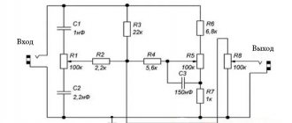
For experiments, you can take any low-power ultrasonic frequency, ready-made or home-made, for example, assembled according to the circuit shown in Figure 1. However, what kind of ultrasonic frequency it is in this case is not so important, so let’s designate it in the diagram with a rectangle with an input and an output (Fig. 2).
Rice. 1. Scheme of a simple homemade ultrasonic sounder using three KT3102 transistors.
Rice. 2. Connection diagram of an oscilloscope with a calibrator to an ultrasonic device.
If rectangular pulses from an oscilloscope calibrator are applied to the ULF input, a tone of 1 kHz frequency is heard in the speaker.
But, to study the operation of the ULF, we need to replace the speaker with an equivalent load, that is, a resistor of the same resistance and power as the speaker (Fig. 3). If this is a ULF according to the circuit in Figure 1, then there is a speaker with a power of 0.25 W and a resistance of 8 Ohms.
Accordingly, we take a constant resistor with a power of 0.25 W and a resistance of 8.1 Ohms (the closest value to 8 Ohms).
Rice. 3. How to replace the speaker with an equivalent load.
Then, we calculate the output signal value for maximum ULF power. The maximum ULF output power according to the circuit in Figure 1 is 0.2 W. The load resistance is 8.1 Ohm, using the formula P = (U^2)/R we find the value U = 1.3V.
This alternating voltage must be at the load equivalent to obtain maximum power (for another ULF with different parameters the value will be different). But this is the effective value, to find out the amplitude you need to multiply it by 1.44.
We get an amplitude of 1.872 V. The amplitude of the pulses coming from the calibrator to the ULF input must be set such that the amplitude of the load equivalent is 1.872 V (approximately 1.8-1.9 V).