Good day to all! In the previous two articles, I talked about building generators based on op-amps (an article about multivibrators here, about triangular voltage generators here). Another type of signal that is used in radio engineering and electronics is a sinusoidal signal.
To assemble a radio-electronic device, you can pre-make a DIY KIT kit using the link.
To generate a sinusoidal signal, various generator and shaper circuits are used, the consideration of which is not possible in this article.
How do sinusoidal oscillations form?
Any generator (not just sinusoidal oscillations) is a closed circuit consisting of an amplifier and a selective circuit (frequency-selective circuit). Moreover, the selective circuit is included in the POS (positive feedback) circuit of the amplifier, where additional amplifiers can be included.
Let's say a signal consisting of a large number of sinusoidal oscillations (harmonics) is received at the input of a selective circuit. Passing through the selective circuit, the oscillations are weakened (the amplitude decreases) to varying degrees, and the phase of these oscillations also changes. As a result, sinusoidal signals with different amplitude levels and phase shifts arrive at the amplifier input from the output of the selective circuit, where they are amplified to compensate for the attenuation by the selective circuit.
Since the selective circuit passes only a harmonic of a certain frequency without changing the phase, then after the amplifier the same harmonic with the same amplitude and phase that the selective circuit passes through will arrive at the input of the selective circuit, and the remaining harmonics will have changed amplitudes and phases of the signal. As a result of the addition of the original signal and the signal coming from the output of the amplifier, only the harmonic to which the frequency-selective circuit is tuned will experience a significant increase in amplitude.
From all of the above, we can conclude that the loop gain of the circuit must be at least unity (ideally equal to 1), and the total phase shift of the circuit must be zero .
There are a large number of sinusoidal generator circuits, or harmonic oscillations as they are also called, which are not possible to consider in one article. Therefore, we will limit ourselves to only a few of them, which are built on op-amps and RC circuits.
How to calculate frequency
Autogenerators and inductance meters are often built on the Wien Bridge. In order not to complicate your life, you usually use R1=R2=R and C1=C2=C . Thanks to this, the formula can be simplified. The fundamental frequency of the bridge is calculated from the ratio:
Almost any filter can be thought of as a frequency-dependent voltage divider. Therefore, when choosing the values of the resistor and capacitor, it is desirable that at the resonant frequency the complex resistance of the capacitor (Z) is equal to, or at least of the same order of magnitude as, the resistance of the resistor.
where ω (omega) is the cyclic frequency, ν (nu) is the linear frequency, ω=2πν
Sine wave generator based on Wien bridge
The Wien bridge sine wave generator, or simply Wien generator, is one of the most common RC sine wave generators. The circuit of this generator is shown in the figure below
Wien generator circuit based on op-amp.
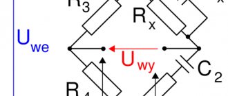
The Wien generator consists of an op-amp DA1, which is covered by OOS (negative feedback) through resistors R1 and R2, as well as POS (positive feedback) using a frequency-selective circuit R3C1R4C2.
The frequency-selective circuit R3C1R4C2 is called a Wien bridge, from which the generator of this type gets its name. This bridge consists of a differentiating circuit R4C2 and an integrating circuit R3C1 connected in series. As is known, to generate a signal, the Wien bridge must provide zero phase shift of the signal. This is ensured by the equality of the time constant of the integrating circuit R3C1 and the differentiating circuit R4C2
Then the frequency at which the phase shift will be equal to zero is determined by the following expression
Under this condition, the transmission coefficient of the PIC circuit will be equal to 1/3. Therefore, in order to compensate for this condition, the transmission coefficient of the OOS circuit must be equal to 3, that is
An oscillator with a Wien bridge provides a sinusoidal output signal with low distortion - about 0.05%. However, this type of generator has a serious problem in that in order to obtain a high-quality sinusoidal signal, it is necessary to ensure precise ratios of resistors in the OOS circuit R1 and R2, that is, to ensure a circuit transmission coefficient equal to three (β = 1/3). So, if β < 1/3, then the resulting oscillations will have strong distortions, and in the case of β > 1/3, even if oscillations occur, their amplitude will gradually decrease and eventually become equal to zero. Therefore, to stabilize the operation of the Wien generator, various automatic amplitude stabilization systems are used.
Shitty embedder life without a sine generator! So I decided to make myself such a device.
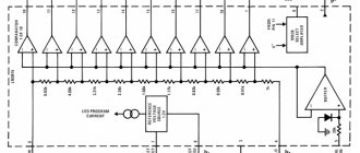
At first I wanted to do it on atXmega - they have a super cool 12-bit DAC. I calculated, wrote (here is one of those places where you need to write in ASMA!), it turned out, but poorly - only 800kSps, that is, you can count on a maximum of 100 kHz of sine. Not much! I thought about it and bought ad9833.
Introduction
This project is one of the long-term projects. On the one hand, I had to make a lot of compromise decisions (and I really don’t like compromises