LM3915 is an integrated circuit (IC) manufactured by Texas Instruments that responds to changes in the input signal and outputs a signal to one or several of its outputs. Due to its design feature, the IC is widely used in LED indicator circuits. Since the LED indicator based on LM3915 operates on a logarithmic scale, it has found practical application in displaying and monitoring the signal level in audio amplifiers.
The LM3915 should not be confused with its relatives LM3914 and LM3916, which have a similar layout and pin assignment. The 3914 series IC has a linear characteristic and is ideal for measuring linear quantities (current, voltage), while the 3916 series IC is more universal and is capable of driving different types of loads.
Brief description of LM3915
The LM3915 block diagram consists of ten identical operational amplifiers operating on the comparator principle.
The direct inputs of the op-amp are connected through a chain of resistive dividers with different resistance values. Thanks to this, the LEDs in the load light up according to a logarithmic dependence. The inverse inputs receive an input signal, which is processed by a buffer op-amp (pin 5). The internal structure of the IC includes a low-power integrated stabilizer connected to pins 3, 7, 8 and a device for setting the glow mode (pin 9). The supply voltage range is 3–25V. The reference voltage can be set in the range from 1.2 to 12V using external resistors. The entire scale corresponds to a signal level of 30 dB in 3 dB steps. The output current can be set from 1 to 30 mA.
DC Voltage Check
Often there is a need to ring the low-voltage circuit of household appliances, or check the integrity of a connection, for example, a wire from headphones.
As a current limiter, you can use a low-power incandescent lamp or a 50-100 Ohm resistor. Depending on the polarity of the connection, the corresponding diode lights up. This option is suitable for circuits up to 12V. For higher voltages, you will need to increase the limiting resistor.
Sound indicator circuit and principle of its operation
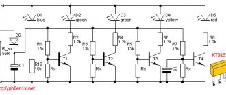
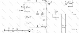
As can be seen from the figure, the circuit diagram of the sound level indicator consists of two capacitors, nine resistors and a microcircuit, the load for which is ten LEDs.
For easy connection of power and audio signals, it can be supplemented with two solder connectors. Anyone, even a beginner radio amateur, can assemble such a simple device. A typical connection provides power from a 12V source, which is supplied to the third pin of the LM3915. It, through the current-limiting resistor R2 and two filter capacitors C1 and C2, goes to the LEDs. Resistors R1 and R8 serve to reduce the brightness of the last two red LEDs and are optional. 12V also comes to the jumper, which controls the operating mode of the IC through pin 9. In the open state, the circuit operates in the “point” mode, i.e. one LED corresponding to the input signal lights up. Closing the jumper switches the circuit to the “column” mode, when the input signal level is proportional to the height of the illuminated column.
A resistive divider assembled at R3, R4 and R7 limits the input signal level. More precise adjustment is carried out by multi-turn trimming resistor R4. Resistor R9 sets the bias for the upper level (pin 6), the exact value of which is determined by resistance R6. The lower level (pin 4) is connected to the common wire. Resistor R5 (pin 7.8) increases the reference voltage and affects the brightness of the LEDs. It is R5 that sets the current through the LEDs and is calculated using the formula:
R5=12.5/ILED, where ILED is the current of one LED, A.
The sound level indicator works as follows. At the moment when the input signal overcomes the lower level threshold plus the resistance at the direct input of the first comparator, the first LED (pin 1) will light up. A further increase in the sound signal will lead to the comparators being activated one by one, which will be indicated by the corresponding LED. To avoid overheating of the IC case, the LED current should not exceed 20 mA. Still, this is an indicator, not a New Year's garland.
How to make an electrician's tester with your own hands?
Some thrifty hobbyists can find many useful things in their “arsenal,” including an earphone (capsule) for the TK-67-NT telephone.
Another similar device, equipped with a metal membrane, inside which there is a pair of series-connected coils, is also suitable.
Based on such a part, a simple sound probe can be assembled.
First of all, you need to disassemble the telephone capsule and disconnect the coils from each other. This is necessary in order to free their conclusions. The elements are placed in the earphone under the sound membrane, near the coils. After assembling the electrical circuit, we will receive a completely working identifier with sound indication, which can be used, for example, to check the tracks of printed circuits for mutual bridging.
The base of such a probe is an electric generator with an inductive opposite relationship, the main parts of which are a telephone and a low-power transistor (preferably germanium). If you do not have such a transistor, then you can use another one with NPN conductivity, but in this case the polarity of the power supply should be changed. If you cannot turn on the generator, the terminals of one (any) coil must be swapped with each other.
You can increase the sound volume by choosing the frequency of the electric generator so that it is as close as possible to the resonant frequency of the earphone. To do this, the membrane and the core must be placed at an appropriate distance, changing the interval between them until the desired result is obtained. Now you know how to make a voltage indicator based on a telephone earphone.
The manufacture and use of a simple voltage probe is clearly shown in the video:
Printed circuit board and assembly parts
The printed circuit board of the sound level indicator in lay format can be downloaded here. It has dimensions 65x28 mm. Assembly requires precision parts. Resistors type MLT-0.125W:
- R1, R5 R8 – 1 kOhm;
- R2 – 100 Ohm;
- R3 – 10 kOhm;
- R4 – 50 kOhm, any trimmer;
- R6 – 560 Ohm;
- R7 – 10 Ohm;
- R9 – 20 kOhm.
Capacitors C1, C2 – 0.1 µF. It is recommended to solder the LM3915 IC not directly, but through a special socket for the chip. The load can use ultra-bright LEDs of any color, even purple. But these are personal aesthetic preferences. To display a stereo signal, you will need two identical boards with independent inputs. More details about the LM3915 can be found in the datasheet here.
The performance of this indicator has been proven in practice by many amateur radio clubs and is still available in the form of MasterKits.
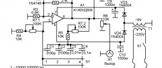
Option for car
A simple circuit for indicating the vehicle's on-board voltage and battery charge. The zener diode limits the battery current to 5V to power the logic chip.
Variable resistors allow you to set the voltage level to trigger the LEDs. It is better to carry out the setup from a network stabilized power source.
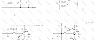
Scale bars on bipolar transistors
Microammeters in the circuits of these devices are included in the collector circuit of the output stages of transistor current amplifiers, made according to a common emitter (CE) circuit. The number of amplification stages is determined by the minimum level to which the dial indicator scale of the audio signal level must respond. The magnitude of the current of the total deflection of the needle can be set by the elements of the alternating voltage divider supplied to the input of the dial indicator circuit for subsequent amplification.
The circuits contain rectifiers for the constantly changing signal of the audio amplifier into direct current to create more comfortable visual control of the volume of the composition being listened to. The scale is performed by digitizing the percentage of the current signal level in relation to its maximum value. The maximum value is set to a volume level whose nonlinear distortion coefficient does not exceed the permissible value and is determined by international quality standards.
Why does the indicator light up when you touch the neutral wire?
I have been asked this question many times. One of the reasons is the incorrect use of the LED indicator. How to properly hold the LED probe indicator when searching for a phase is written in the article above.
The second possible reason for this behavior of the indicator is a break in the neutral wire. For example, a circuit breaker installed after the meter on the neutral wire tripped. In old apartments this is not uncommon and is a gross violation of the electrical wiring. It is imperative to remove the machine from the neutral wire or short-circuit its terminals with a jumper.
When the neutral wire breaks, a phase is supplied to it through devices connected to the electrical network, for example, through a switch backlight indicator, a TV in standby mode, any charger, a computer turned off only by the start button and other electrical appliances. The indicator shows this. In this case, the neutral wire can be dangerous and touching it is unacceptable. It is necessary to find and repair a break in the neutral wire, which may also be located in junction boxes.
Operating principle of an indicator screwdriver
Regardless of the type of device, its main idea is to provide a signal about the presence of voltage in the network. In this case, contact models determine the voltage by touching a bare conductor (cable core, contact surfaces of devices, conductive liquid, etc.), while non-contact models “read” the electromagnetic field of the area.
However, in any case, the electrical circuit in a conventional indicator screwdriver must be closed to obtain information - namely, press the contact plate at the end of the product with your finger. A person is also a conductor of electricity, and this is the principle of operation of the device.
All products are divided into groups not only according to design features, but also according to sensitivity. High-quality electronic models are deservedly considered the most accurate, while those with a neon lamp are the most insensitive. The last type of tool accepts voltage from 60 V.
What is an indicator screwdriver?
This is a tool designed to detect voltage in the electrical network, including hidden ones. Externally, the model may look like a regular flat-head screwdriver with a transparent handle or have a different appearance. However, a probe in the form of a flat bit is required - this is what is used to check the contacts.
Insulation of the handle is also required - the metal part of the device should not come into contact with unprotected human skin, and any metal parts on the handle should not have direct contact with the probe.
They produce products of contact and non-contact types, with different options for sending signals - light, sound, in the form of information on a digital display - as well as with additional functions.
Simple
A working electrical circuit is installed in the case, with a standard set of elements: transistor, resistor, indicator - neon bulbs. The zero phase is the person who closes the contact plate. The tool is not functional - it detects the voltage on the wire, but often does not work when the network voltage is less than 60 Volts. Not suitable for searching for network breaks.
Universal
Portable devices with a wide range of capabilities. An instrument of this type performs contact and non-contact testing, determines open circuits and short circuits using “ringing” of networks, and light and sound warnings help with this. Universal probes are used when repairing or setting up electronic devices and vehicles; they are designed to work with direct and alternating current. The tester operates on a battery, the charge of which is monitored. If the battery loses charge, the universal screwdriver will not work.
The type of indicator screwdriver is selected depending on the intended work. For everyday use, a simple model is sufficient, but for working with electronic devices, choose a universal device.
Method of using an indicator screwdriver
- Non-contact - for a network with voltage up to 600 V. The tip is passed along a wire or electrical appliance that requires testing. If there is voltage, the light will also light up. This is a convenient way to track breaks in the circuit.
- Contact - an indicator screwdriver is used in networks up to 250 V. While holding your finger on the sensor, the tip of the probe is touched to the place that needs to be checked. If there is voltage, the indicator light will light up.
Life-threatening voltage detector, manufacturing
The device is made with three transistors, without a board for surface mounting.
Please note that the circuit uses transistors of different structures. There are no special requirements for them; almost any will do. An LED and a buzzer are used as signaling elements. The role of the antenna is played by a piece of wire 5 cm long.
The detector is powered by two little finger elements.
The body is a transparent plastic tube.
After assembly, if all elements of the circuit are in working order, the detector starts working immediately and does not need adjustment.
A few words about the containers around us
How does a capacitive voltage indicator work? To understand this, let's go back for a moment to electrical circuit theory and remember how a capacitor functions. It has two conductors, or plates, separated by a dielectric. Many people think that capacitors are separate elements of electronic circuits, but in reality the world is filled with capacitors whose presence we usually simply do not notice. Here's an example. Suppose you are standing on a carpet covering a concrete floor directly under a 220-volt light fixture. Although you may not feel it, your body is conducting very little (on the order of a microampere) alternating current because it is part of a circuit consisting of two series connected capacitors. The two plates of the first capacitor are the filament in the light bulb and your body. The dielectric is the air (and possibly your hat) between them. The plates of the second capacitor are your body and the concrete floor (it is a fairly good conductor).
The dielectric of the second capacitor is the carpet plus your shoes and socks. Since the concrete floor is well grounded, as is the neutral wire of the power supply network, a voltage of 220 V is applied to the circuit of these two series capacitors.