We will talk about a very common integrated circuit (IC) audio power amplifier LM386, manufactured by National Semiconductor (now fully part of Texas Instruments) [1]. Indeed, the supply voltage of the microcircuit can be in the range of 4...12 V, and the quiescent current consumption is only 4 mA, which is ideal for most audio projects powered by batteries. The amplifier develops an output power of 0.5 W with a supply voltage of 9 V and a load resistance of 8 Ohms. If we add that Kus. This IC can be easily selected from 20 to 200 using two external elements, and its output voltage is automatically set to half the supply voltage, it is clear why this IC has remained popular for many years.
The title of the project reflects what has been said - both the microcircuit and sets based on it are extremely in demand among radio amateurs, in this sense the LM386 audio amplifier is truly a champion. See, for example,
"New super mini amplifier based on LM386, 3V - 12V DIY Kit"
I propose to familiarize yourself with the capabilities of the mass-produced LM386 microcircuit and suggest my options for its application.
Contents
- 1 Characteristics, functional diagram and selection of external elements of amplifiers on the LM386 IC
- 2 Amplifier circuits on IC LM386 2.1 Amplifier with a gain of 200
- 2.2 Amplifier with a minimum number of external elements and a gain of 20
- 2.3 Amplifier with gain 50
- 2.4 Amplifier with bass boost
- 2.5 Schematic diagram of an amplifier for an AM radio receiver
- 3.1 LM386 amplifier with headphone jack
- 4.1 Universal amplifier parts and circuit board
Working of LM386 audio amplifier circuit
A simple yet effective audio amplifier is designed using LM386 audio amplifier IC. The operation of the circuit is very simple as all the work is done by the LM386 chip itself.
When power is applied to the circuit and the appropriate audio input is applied, the LM386 amplifies the input signal by 200 times and drives the output speaker.
One of the main problems with audio amplifiers like the LM386 is noise. Surprisingly, despite the circuit being based on a breadboard, there was very little noise coming from the speaker.
↑ Characteristics, functional diagram and selection of external elements of amplifiers on the LM386 IC
The LM386 audio power amplifier is used in portable electronic equipment.
The analogue of LM386 is KA386 from Samsung, the domestic analogue is KR1438UN2. The LM386 integrated circuit became popular among Russian amateurs with the fall of the Iron Curtain; before that time, Soviet electronics engineers had chosen the K157UD1 microcircuit, intended for use in magnetic recording equipment, as a mass amplifier.
Main technical characteristics of the LM386 chip
Output power, Pout = 250…500 MW, Load resistance, Rн = 8 Ohm.
Gain, Ku = 26…46 dB, Frequency band, B = 20 Hz..60 kHz, Input impedance, Rin = 50 kOhm, Harmonic distortion, Kg = 0.2%, Supply voltage, Up = 4…12 V, Quiescent current, Io=4 mA. Table 1 will help you quickly select the required supply voltage depending on the load resistance and the required output power.
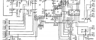
In Fig.
1 shows the functional diagram of LM386. On it, transistors of the pnp structure VT1, VT2 and VT5, VT6 form a differential amplifier, in which each of the inputs is connected to a common wire through resistors R1 and R2, which actually determine the typical input resistance of 50 kOhm. The load of the differential amplifier is a current mirror on transistors VT3, VT4, and the output (transistor VT5) is connected to the input of the voltage amplifier VT7, connected according to a common emitter circuit. The collector circuit VT7 includes diodes VD1, VD2 in series, which serve to create a bias at the bases of the output stage, and a current source Io.
The power amplifier operates in class AB and is made using transistors VT8 - VT10, connected in a circuit with a common collector, so the voltage gain of the output stage is close to unity.
Rice. 1. Functional diagram of LM386 low voltage audio amplifier
Please note that in order to minimize the voltage drop across the output stage transistors and obtain maximum output power, the circuit does not include overload protection elements.
Resistors R2 and R3 set the current of the differential amplifier transistors. The connection point of resistors R2 and R3 is connected to the external pin of the microcircuit (pin 7), intended for connecting an external filter capacitor.
The emitters of the differential cascade transistors VT2 and VT5 are connected somewhat non-standardly: they are not connected together, but contain negative feedback resistors. Two of them, R4 and R5, are connected in series between the emitters VT2 and VT5, and the third, R6, is connected to the emitter VT5 and the output of the output stage (emitters VT8, VT9).
The voltage gain with this connection is equal to twice the ratio of resistance R6 to the sum of the resistances of the resistors installed between the emitters of transistors VT2 and VT5 (R4 + R5):
Ku=2R6/(R4+R5)=2•15/(0.15+1.35)=20 (1)
The emitter pin VT5 and the connection point of resistors R4, R5 are connected to the external pins of the microcircuit (pins 1 and 8, respectively) and are intended to set the required gain, which can vary in the range from 20 to 200. If you short-circuit pins 1 and 8 to AC using an external capacitor, then in expression (1) the resistance of the internal resistor R5 is taken equal to zero, and the total voltage gain will be 200.
By connecting a series chain consisting of a resistor and a capacitor between pins 1 and 8, we can vary the gain from 20 to 200:
Ku=2R6/(R4+R5Rin/(R5+Rin)),
where Rin is the resistance of the external resistor, kOhm.
The capacitance of the external capacitor Svn must be chosen such that in the operating frequency range its resistance to alternating current is much less than Rin. When Rin = 0 we get Ku = 200; with Rin = ∞ we get Ku = 20, and with Rin = 680 Ohm, the gain Ku = 50.
To obtain the required amplitude-frequency response (AFC), you can include complex elements both between pins 1 and 8, and between pins 1 and 5 of the microcircuit.
Elements for forming the required frequency response can be included not only between the indicated terminals, but also the common wire [2]. For example, you can install a chain between pin 1 and the common wire consisting of an oxide capacitor and an external resistor Rin.
Interestingly, in this case it is possible to obtain a gain of about 70 dB. With Rin = 4.7 Ohm we get Ku = 70 dB; with Rin = 15 Ohm we have Ku = 60 dB, and with Rin = 47 Ohm the gain will be Ku = 50 dB.
Such circuits can find application in highly sensitive devices (direct conversion receivers, ultra-sensitive microphones [3 - 5], etc.), while it is possible to do without an additional amplifier stage on a transistor, connected in front of the amplifier on the LM386 chip.
Dimensions LM386
The LM386 amplifier is available in four modifications. The first three of them, namely LM386 N-1, N-2, N-3, provide very low distortion and work well with supply voltages ranging from 4 to 12 volts DC.
The fourth type, LM386 N-4 operates with operating voltages from 5 to 18 volts DC. These are the extreme values of the supply voltage, beyond which the amplifier either stops working or overheats and fails.
↑ Amplifier circuits on IC LM386
↑ Amplifier with gain 200
The schematic diagram of an amplifier with a gain Ku=200 (46 dB) is shown in Fig. 2 a, b. The first of them (Fig. 2 a) shows the functional diagram of the LM386 IC, which allows you to better understand the operation of the amplifier, and the second (Fig. 2 b) shows the microcircuit in the form of a “black box”, which makes it easier to lay out the printed circuit board and check the correctness installation of elements mounted on it.
Rice. 2. Amplifier with a gain of 200
Resistor R1 serves as a volume control, capacitor C1 is a filter. Capacitor C2 shunts pins 1 and 8 of the DA1 microcircuit with alternating current, thereby achieving maximum gain; capacitor C4 serves for power supply decoupling, which is important when working with a discharged battery, when its internal resistance increases.
Chain C3, R2 is designed to increase stability when the amplifier operates with a capacitive load. Sometimes its installation is neglected, which is not a crime, but is undesirable, since it can present a “surprise” at the most inopportune moment. Load BA1 is connected to the output of the IC through an isolation capacitor C5.
↑ Amplifier with a minimum number of external elements and a gain of 20
In Fig. Figure 3 shows a circuit with a minimum number of elements, having a voltage gain Ku=20 (26 dB). Here, pins 1 and 8 of the microcircuit are left free, and the filter capacitor connected to pin 7 is excluded from the circuit. As a result, the entire amplifier contains only seven elements, including the BA1 dynamic head.
Rice. 3. Amplifier with a minimum number of external elements and a gain of 20
↑ Amplifier with gain 50
Another version of the circuit is shown in Fig. 4. With the values of the elements shown in this diagram, a voltage gain of Ku=50 (34 dB) is provided.
Rice. 4. Amplifier with a gain of 50
Compared to the previous circuit, three elements have been added: two capacitors and a resistor. In table Figure 2 shows the values of resistor R2 to obtain other voltage gains.
↑ Amplifier with bass boost
An example of an amplifier in which the required frequency response is formed is the circuit shown in Fig.
5. Here the voltage gain is changed by shunting the internal feedback resistor (R6), accessible through pins 1 and 5 of the LM386 chip. Bypassing the R2, C2 chain allows you to get a frequency response increase of about 6 dB at a frequency of 85 Hz, which can be used to improve the sound of small-sized speaker systems.
The voltage gain of the amplifier at a frequency of 1 kHz is Ku=10 (20 dB).
Rice. 5. Amplifier with bass boost
↑ Schematic diagram of an amplifier for an AM radio receiver
Another example of using an IC as an amplifier for a small-sized AM radio receiver is shown in 6. In this circuit, the broadcast signal after the detector enters through capacitor C1, which eliminates the transfer of the DC component to the volume control R1.
Rice. 6. Schematic diagram of an amplifier for an AM radio receiver
The signal from the middle pin R1 is supplied to the non-inverting input of the DA1 microcircuit through a decoupling circuit - a low-pass filter R2, C2, which eliminates the entry of residual high-frequency voltage. For the same purposes, the L1, C7 chain is connected at the amplifier output. The fact is that the amplifier on the DA1 chip is quite broadband (the bandwidth is about 300 kHz) and, without taking such measures, serves as an excellent source of radio emissions in the long-wave and medium-wave ranges.
Resistor R3, connected in parallel with coil L1, serves to eliminate unwanted resonances in the audio frequency range. The voltage gain of the amplifier is maximum (Ku=200).
Along with the oxide capacitor C6, a ceramic capacitor C5 is included, used for high-frequency isolation in the power supply circuit; The filter capacitor connected to pin 7 of the microcircuit (C3) is not forgotten in this circuit either.
Coil L1 is a ferrite bead with a wire running inside (Ferrite Bead).
Description LM386
The LM386 is a versatile Class AB audio amplifier IC that can be used in a wide variety of applications. The LM386 has been around for decades and is still used as an amplifier in computer speakers and portable stereo systems.
The LM386 is a low-voltage power amplifier with a non-active power consumption of 24 mW, making it suitable for battery-powered applications. The most common package for the LM386 is the 8-pin DIP. The following figure shows the pinout diagram of the LM386 chip.
↑ Other applications of the LM386 chip
↑ Amplifier based on LM386 with headphone jack
In Fig. 7 shows an amplifier with the ability to connect headphones. In the diagram, the input voltage from the audio signal source is supplied through capacitor C1, which eliminates the DC component to the volume control R1.
Rice. 7. Amplifier with headphone jack
The second capacitor (C2), connected between the middle terminal of R1 and the non-inverting input, is in principle not needed, but such a circuit solution eliminates rustling noise in the event of a possible poor quality variable resistor, and also reduces the half-voltage offset at the amplifier output.
The headphone jack is connected through decoupling capacitor C5 in such a way that if there is no headphone plug, speaker BA1 is connected, and when the plug is turned on, the speaker is turned off.
The purpose of the remaining elements of the amplifier was discussed above. The voltage gain is minimal (Ku=20).
↑ Intercom on LM386
Taking as a basis an amplifier with maximum gain (Fig. 2), you can get a simple intercom. As can be seen from the diagram presented in Fig. 8, it added a power switch and a “Receive – transmit” switch, which ensures alternate operation of dynamic heads BA1 and BA2 as a microphone or loudspeaker.
Rice. 8. Intercom
The device allows you to organize wired communication between two subscribers. The communication range reaches several hundred meters.
The scope of application of this design: communication between two subscribers, games, etc. An amplifier with a BA1 dynamic head is located at the main communication point, and another dynamic head is located at a remote communication point. The connection between the main and remote communication points is made with a multi-core two-wire telephone cable. The design is powered by a 9 V battery of the Krona type.
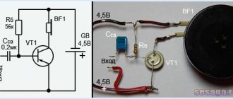
↑ Low distortion sine wave generator on LM386
The same amplifier can be converted into a sinusoidal signal generator with low harmonic distortion without great expense. The generator circuit with a Wien bridge is shown in Fig. 9.
Rice. 9. Low distortion sine wave generator
Recall that the frequency of the generator is determined by the expression:
fo=½Π√(R1R2C1C2)
Most often, R1=R2 and C1=C2 are chosen, and the expression is simplified:
fo=½ΠR1C1
The second requirement is that the amplifier's negative feedback ratio must be exactly 1/3 [6]. Under these conditions, undamped oscillations arise in the circuit. If this ratio is less than 1/3, the amplitude of the oscillations will increase rapidly over time until the output voltage becomes a square wave.
If the negative feedback coefficient is more than 1/3, the oscillation amplitude will tend to zero after some time. It is clear that it is possible to set the ideal coefficient value if you use an automatic amplitude adjustment system.
For this purpose, a negative feedback circuit R3, HL1 is provided, which affects the gain in such a way that the oscillation amplitude is stabilized at very low nonlinear distortions (about 0.05%).
If the output voltage of the generator increases for some reason, the current through R3 will also increase, as well as the voltage on the nonlinear element - the incandescent lamp HL1. The filament of the incandescent lamp will heat up and its resistance will increase, which will lead to a decrease in the depth of negative feedback and a decrease in the voltage at the output of the generator. When the output voltage of the generator decreases, the processes occur in the opposite direction, resulting in automatic stabilization of the gain.
With the element values indicated on the circuit diagram, the frequency of the generated oscillations is 1 kHz, and the amplitude is about 2 V eff.
↑ Rectangular pulse generator on LM386
The diagram shown in Fig. 10 is a square wave signal generator.
Rice. 10. Rectangular pulse generator
Amplifier DA1 plays the role of a comparator. Positive feedback is implemented using a divider R1, R2 connected to the non-inverting input of the amplifier. Feedback coefficient Kos=R2/(R1+R2). The negative feedback includes an integrating circuit R3, C1.
The generator oscillation period for symmetrical rectangular signals is:
T=2R3C1ln[(1+Kos)/(1-Kos)]
When Kos=0.462 the formula simplifies:
Т=2R3C1, and frequency f=½R3С1
The maximum frequency of oscillations generated by the circuit is limited by the rate of rise of the output voltage of amplifier DA1.
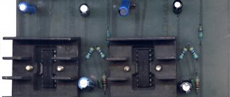
↑ Universal amplifier based on IC LM386
Shown in Fig.
11, the circuit diagram of a universal UMZCH on the LM386 IC opens up scope for creativity, since it provides a ready-made functional unit for a wide range of applications (see Table 3). Fragment excluded. The full version is available to patrons and full members of the community.
Rice. 11. Universal amplifier based on IC LM386
↑ Universal amplifier parts and circuit board
Resistors of the MLT, MON, S2-33N types with a power of 0.25 or 0.125 W are used.
Ceramic capacitors KM-5, KM-6, K10-17, K10-47, as well as film capacitors K73-9, K73-17 or K73-24; oxide capacitors K50-35. The dynamic head is broadband, with an impedance of 8 Ohms, a power of 0.5...3 W, for example 1GDSH-6-8. All parts can be replaced with imported analogues. Details
DA1 – LM386N (L) chip, DIP8-300 housing – 1 pc., SCS-8 Narrow dip socket – 1 pc., R1 – Res.-0.25W-4.7 kOhm (Yellow, purple, red, gold) – 1 pc., R2 – Res.-0.25W-10 kOhm (Brown, black, orange, gold) – 1 pc., R3 – Res.-0.25W-680 Ohm (Blue, gray, brown, gold) – 1 pc., R4 – Res.-0.25W-300 Ohm (Orange, black, brown, gold) – 1 pc., R5 – Res.-0.25W-160 Ohm (Brown, blue, brown, gold) – 1 pc., R6 – Res.-0.25W-51 Ohm (Green, brown, black, gold) – 1 pc., R7 – Res.-0.25W-47 Ohm (Yellow, purple, black, gold) – 1 pc., R8 – Res.-0.25W-15 Ohm (Brown, green, black, gold) – 1 pc., R9 – Res.-0.25W-4.7 Ohm (Yellow, purple, gold, golden) – 1 pc., R10 – Res.-0.25W-10 Ohm (Brown, black, black, golden) – 1 pc., R – Variable resistor 10 kOhm for SP3-4am nut – 1 pc., C1 – Cond. X7R 0.22 µF ceramic imp (EIA Code 224); K10-17 b-N90-10% 0.22 uF – 1 pc., C2 – Cond. X7R 1000pF ceramic imp (102); KM-6 b- 1000 pF – 1 pc., C3, C4 – Cond. 10/16V 0511 +105C – 1 pc., C5, C9 – Cond. X7R 0.047 µF ceramic imp (473); K10-17-1a-N90 0.047 µF – 2 pcs., C7 – Cond. X7R 0.033 µF ceramic imp (333); K10-47-100V 0.033 uF – 1 pc., C6, C8, C10 – Cond. 220/16V 0611 +85°C – 3 pcs., J1…J9 – Plug on PLS-2 board – 9 pcs., Printed circuit board 75×25 mm – 1 pc.
In Fig. Figure 12 shows the amplifier circuit board.
Rice. 12. Circuit board for universal UMZCH on LM386
A laboratory power source based on a rechargeable battery is suitable for experiments with the amplifier [8].
Amplifier chips
Everyone is accustomed to the fact that audio amplifiers depend on many individual components or on energy-intensive vacuum tubes to produce high-quality sound. As in other industries, the advent of integrated circuits caused a breakthrough in the world of audio systems, allowing the use of any number of operational amplifiers designed for audio systems.
Such integrated circuits are called IC audio amplifiers, audio amplification chips, or on-chip amplifiers. They typically require a few additional components, are simple in design, and consume less current than their discrete and tube counterparts.
All this brings us to the LM386 amplifier, created by Texas Instruments in 1983. It can be found in low-voltage battery applications around the world.
Its characteristics:
- easy to power (uses one-way power supply)
- low heat dissipation (does not require heat sink)
- productive/efficient
- there is a variant with a double-row arrangement of pins / there is a double-row variant
This means that this chip is in favor with tinkerers around the world and is an excellent testing ground for experiments with chip amplifiers. And don't forget about its low cost. Today we will try to assemble a simple mini sound amplifier for speakers based on this chip.
↑ List of sources
1. LM386 - Low Voltage Audio Power Amplifier. 2. Digest HF + VHF // Radioamator, 2009, No. 2, p. 56 (How to get 74dB gain from LM386). 3. Mosyagin V. Narrow-directional microphone // Radio, 2002, No. 5, p. 54, 55. 4. Merryfield T. Super-Ear Audio Telescope // Everyday Practical Electronics, 2005, No. 6, p. 388 – 392. 5. Stewart J. The Big Ear // Nuts & Volts, 2008, No. 10, p. 34 – 39. 6. Faulkenberry L. Applications of operational amplifiers and linear ICs. – M.: Mir, 1985. 572 p. (pp. 250 - 254). 7. Digest (Test of the microphone effect of capacitors) // Radiohobby, 2000, No. 5, p. 25. 8. Great article about a small amplifier based on the TDA2822M chip. Datagor article. 9. Directory. Microcircuit UMZCH LA4525. UMZCH LA4534M microcircuit // Radioconstructor, 2008, No. 9, p. 20 - 22. 10. Mosyagin V.V. For a young radio amateur to read with a soldering iron. (Series “SOLON - for radio amateurs”, issue 17). – M.: SOLON – Press, 2003. – 208 p. 11. Mosyagin V.V. Secrets of amateur radio skills. (Series “SOLON - for radio amateurs”) - M.: SOLON - Press, 2005. - 216 p.