At the beginning of December, I decided to give a gift to my friend on the Japanese literature forum.
He was the translator of two books that became one of my favorites, and I decided to at least somehow thank him for his work. Knowing that he was a guitarist dreaming of a tube amp, he decided to make a simple tube amplifier for him. The scheme itself does not claim to be new. In this article, I rather want to tell you how to make a beautiful and useful thing for a guitarist from a pile of junk.
↑ Amplifier circuit
I'll go directly to the diagram itself.
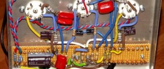
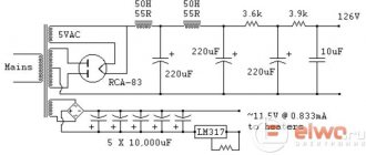
It is simple, preamplifier + cathode follower on 6N2P and terminal on 6P14P. The lamps were heated with direct current according to the “capacitance – diode – capacitance” scheme. Powering the anodes using a classic “capacitance – resistor – capacitance” filter. I assembled the circuit, and there is a small background at the output - the result of the absence of a choke in the anode voltage filtering circuit and not entirely competent ground wiring. In a word, he was in a hurry. I tried various modifications, but nothing helped. I decided to re-distribute the ground on the board and use an electronic choke on an IRF830 field-effect transistor. It was experimentally found that the ripple level in this circuit with 4 capacitors with a total capacity of 4.4 µF is similar to a classic LC filter with a capacitance of about 350 µF. In terms of size and cost, the electronic throttle is in an advantageous position. Many experienced people may criticize me. I understand that a regular 3-5 G choke will give better results, but what to do if there is simply nowhere to put it, the case does not allow it. In the photo below there is a transistor without a radiator; later I screwed a small radiator to it.
Among the features of the amplifier circuit, I would also note the presence of a full-fledged tone block in the gap between the preamplifier and the cathode follower. “High”, “low”, “mid” and “level” – everything that is needed for the guitarist to catch satisfying shades of sound. The tone block board is separated from the main one and is attached to the rear wall of the front panel. I didn’t want to drag out a web of wires to each potentiometer, so I laid out a scarf, to which there are only three wires - input, output and ground.
There are no distortion stages in the circuit. The recipient of the gift already has a tube higen pedal for his guitar, and there is no room in the case.
Re-routing the ground and using an electronic throttle reduced the background to nothing.
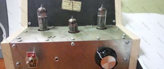
I used TV-2Sh as an output transformer due to the lack of alternatives. I installed all the elements in the housing, soldered the transformer power wires and the outputs of the secondary windings of the output transformer to the power socket and audio terminals, respectively. Covered it with a lid. I installed Boss 19.5mm knobs on the potentiometers. All is ready!
Before shipping, I ran the amplifier for 6 hours for two days. Nothing burned, no extraneous sounds or noises appeared. There were 14 days left until the New Year and there was no longer any time to delay; it was necessary to send a gift and rely on the Russian post office.
The “delivery package” included the amplifier itself, 2 spare lamps, a power cable, a 2-meter audio cable for connecting to the speaker, and even a 25-watt soldering iron with a minimum supply of tin and rosin. Even though I soldered the terminals for connecting to the speaker using audio cable, I still decided to play it safe and sent a soldering iron, in case the terminals didn’t fit.
Russian Post did not disappoint and did not turn the gift into last year’s, everything arrived on time. The recipient was pleasantly surprised.
Tube guitar amplifier, push-pull circuit 6p14p + 6n2p
After several years of playing transistor amps, every guitarist sooner or later wants to play a tube amp. Definitely on some Marshall or Fender with a 4 x 12 cabinet.
This desire overcame me in 2008, but due to the lack of money for a professional apparatus, I began to look for ways to materially realize this idea through more affordable means. Because the experience of assembling microcircuit power amplifiers, light music and guitar effects allowed me to become more familiar with tube circuitry.
In the fall of 2009, inspired by the Peta-10 stereo rack amplifier from , I decided to assemble a guitar terminal using a similar circuit, which was painfully reminiscent of the Fender Blues Junior circuit. This factor, of course, only added weight to this idea. Although, it is worth admitting, my very first acquaintance with the lamp was a project to remake the amplifier from the Lomo 90U-2 film installation. The beast looked like a Soviet bread box, but it acquired on board two power switches, an indicator light and 6.3 jacks for input and output.
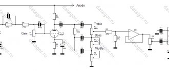
The Fender Blues Junior circuit is simple enough for a radio amateur who is inexperienced in the tube, and does not require complex tuning, except for setting the bias voltage. The selection of lamps in such a budget scheme is also not mandatory. Instead of 12ax7 and El84, domestic 6n2p and 6p14p are installed without any modifications. The only thing is that the filament for 6n2p needs 6 V, and not 12 - as for 12ah7.
In the end I got something like this
, featuring useful additions to the power supply. Namely, an RC circuit in the primary winding of a power transformer, which dampens the click when the amplifier is turned on/off. I installed 100R/0.5W resistors in the filament windings, which reduced the low-frequency background of 50 Hz heard in the speakers several times. It is also recommended to twist the filament wires with each other to further reduce interference. I tested this innovation from my own experience - 100% confirmed fact.
In the selection of transformers, preference was given to the Soviet TN-36 and the anode green counterpart from the TA series. The output transformer on TP-30 iron was kindly provided to me by S.N. Marichev. I found a sheet of duralumin and, without thinking twice, decided to use it as a chassis. The hanging installation was carried out on the petals of the lamp panels and on plastic terminals (after all, you cannot place all the elements on the petals, no matter how much you would like to).
No adjustments were provided, because initially this function was assigned to the pre-amplifier. This explains the following decision: the 6.3 input and output jacks are also removed to the rear panel. The face of the device was designed in the style of technical minimalism: buttons for turning on the filament and anode and an indicator light. As practice has shown, no knobs on the front panel are particularly required. If desired, you can put a 100 K potentiometer with a logarithmic dependence at the input to adjust the volume. It all depends on your technical goals.
I first connected the guitar to the Ibanez Tone Blaster 30R amp, in which I implemented a “send & return” interrupt circuit; after the return jack from the effects loop, I soldered in a volume potentiometer, which was set to zero. Thus, the signal was taken from the pre-amplifier of this amp and fed to the input of a tube terminal, the output of which was connected to a guitar cabinet equipped with a 12-inch Eminence Cannabis Rex speaker.
The result of the first lamp construction was 100% satisfying. And in volume, and in volume, and in the transmission of high frequencies. I never used the transistor end of the combi again. It seemed so poorer in overtones compared to the lamp. But the preamp of the amp with a built-in reverb, in principle, produced a quite tolerable sound. Even for jazz playing on a Greg Bennett Royal semi-acoustic.
So, making a tube amplifier with your own hands is no more difficult than assembling the TDA7294; the main thing here comes down to finding and selecting a high-quality output transformer and adjusting the bias voltage. If the circuit is with auto-bias, then the matter is even simpler; you only need to select resistors in the cathode circuit.
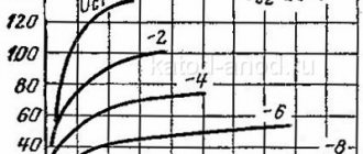
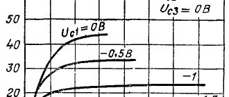
Main parameters of 6P14P
Sound amplifier 200 watt
at Un = 6.3 V, Ua = 250 V, Uc2 = 250 V, Rk = 120 Ohm
| Name | 6P14P | 6P14P-V | 6P14P-EV | 6P14P-ER |
| Filament current, mA | 760 ± 40 | 760 ± 40 | 760 ± 40 | 800 ± 60 |
| Anode current, mA | 48 ± 8 | 48 ± 8 | 48 ± 8 | 48 ± 8 |
| 2nd grid current, mA | 5+2 | 5+2 | 5+2 | 5+2 |
| The same in dynamic mode (at Uс1 ≈ 3.4 V, Ra = 5.2 kOhm), mA | 11 | 9+2 | 9+2 | 11 |
| Leakage current between cathode and heater, μA | ≤ 25 | ≤ 30 | ≤ 30 | − |
| Characteristic slope, mA/V | 11,3−2,3 | 11,5+3−2 | 11,5+3−2 | 12+2−3 |
| Output power (at Ra = 5.2 kOhm), W | 4,2−1,2 | 4,3−1,2 | 4,3−1,2 | 3,4 − 4,3 |
| The same at Un = 5.7 V, W | ≥ 2 | ≥ 2,7 | ≥ 2,7 | − |
| Nonlinear distortion factor, % | 8+2 | 8+2 | 8+2 | 8 − 10 |
| Internal resistance, kOhm | − | − | − | − |
| Insulation resistance cathode-heater, MOhm | ≥ 5 | ≥ 10 | ≥ 10 | − |
| Interelectrode capacitances, pF: | ||||
| — entrance | 11 | 11 ± 2,5 | 11 ± 2,5 | 11+2,5−3,5 |
| - day off | 7 | 8 ± 2 | 8 ± 2 | 8,5 ± 2 |
| — checkpoint | ≤ 0,2 | 0,175−0,4 | 0,175−0,4 | 0,175 |
| Operating hours, h | ≥ 3000 | ≥ 1000 | ≥ 5000 | ≥ 5000 |
| Criteria for evaluation: | ||||
| — output power (at Ra = 5.2 kOhm), W | ≥ 2,0 | ≥ 2,7 | ≥ 2,7 | ≥ 2,7 |
| — reverse current of the first grid, μA | − | ≤ 1,5 | ≤ 1,5 | ≤ 1,5 |
Schematic diagram
Tda7294 - 100 watt integrated low-frequency amplifier, circuit and characteristics
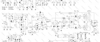
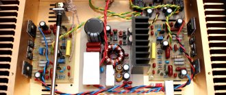
The two-stage power amplifier is built with a push-pull output stage according to an ultralinear circuit (Fig. 1). The amplifier has two features - the absence of a separate bass reflex and the presence of a stabilized current source in the cathode circuit of push-pull stage lamps.
The idea of using a current source in the output stage was recommended to me by Perm radio equipment designer O.I. Kataev.
The first stage of the amplifier is assembled on a 6NZP double triode. This lamp, with average values of slope and gain, has a feature that is important for stereo amplifiers - symmetrical pinout. Therefore, the cascades of the left and right channels can be made completely symmetrical both in surface-mounted and printed-circuit mounting.
Rice. 1. Schematic diagram of a 6P14P push-pull tube power amplifier.
The signal from the volume controls (variable resistors R1.1 and R1.2) in each channel is fed through a separating capacitor to the triode grid of the lamp VL1. The amplified signal from the load resistor R6 (R7) through the capacitor C5 (C6) is supplied to the control grid of one of the output lamps VL2 and VL3 (hereinafter, only the elements of the right channel - the top one in the circuit) are indicated.
The control grid of the VL3 lamp is connected to a common wire, so the lamps are excited in antiphase due to cathode coupling and the high internal resistance of the current source.
↑ Setting up an amplifier is not difficult.
First of all, make sure that the power supply is working.
The voltage “+275” can be in the range from 250 to 300 V (depending on the type of transformer used). An alternating voltage of 6.3 V is considered within normal limits if it is not lower than 6.0 V, but not higher than 6.5 V. Then the amplifier board is connected to the power supply. We are not installing lamps yet. Table 1. Voltages on sockets without lamps
| Lamp socket | Leg | ||||||||
| 1 | 2 | 3 | 4 | 5 | 6 | 7 | 8 | 9 | |
| VL1 | +49 | 0 | 0 | +275 | — | +275 | 0 | 0 | +49 |
| VL2 | — | 0 | 0 | +49 | +49 | — | +275 | — | +275 |
After connecting the board, you need to check the incoming voltage to the lamp sockets. Table 1
The voltage values for this case are given. Be very careful about measuring the voltage on the 2nd knife of the VL2 socket - there should be an absolute “0”. The slightest positive DC voltage will mean only one thing - capacitor C4 has a leak and must be replaced before the lamps are turned on. The voltage “+49” is the voltage that is obtained at the divider R11-R12, and if you changed the values of these resistors, then it may differ from the specified one, but in any case it should correspond to the voltage at the connection point R11-R14. The absence or significant discrepancy in voltage “+275” on any leg indicates a malfunction in this circuit, usually a break. Of course, C3 or C5 may still be faulty, but in this case the effect of their failure will be expressed by charring resistors R7 or R10, respectively.
Table 2. Voltages on lamp legs
| Lamp socket | Leg | ||||||||
| 1 | 2 | 3 | 4 | 5 | 6 | 7 | 8 | 9 | |
| VL1 | +49 | +2,0 | 0 | +150 | — | +150 | 0 | +2,0 | +49 |
| VL2 | — | 0 | +6,0 | +49 | +49 | — | +250 | — | +255 |
If everything is in order, turn off the power, connect the speakers or equivalent load (which can be a resistor with a resistance of 3.9 to 8.2 Ohms and a power dissipation of at least 2 W), remove jumper JP1 and install the lamps. We supply power to the amplifier and immediately control the voltages on the legs of the 3 VL2 lamps again. As the cathodes heat up, it should smoothly increase to +6.0..6.1 V and then remain there - this will indicate that the lamps have reached normal operating mode. A voltage higher than 6.3 V indicates severe wear of the lamp (the slope of the characteristic has decreased, usually a consequence of gas contamination inside the lamp cylinder), a low voltage (from about 5.8 and below) is also typical for lamps that have been operating for a long time (loss of emission) - Such lamps must be replaced. The voltages on the other legs of the lamps are shown in Table 2. The voltages on the anodes and cathodes of VL1 are indicated for the case of open JP1 - when it is installed in place, the voltages on the anodes will drop to 110..120 Volts, and on the cathodes to 1.7..1.8 B. If the voltages are within the permitted limits, you can try to apply a small amplitude signal to the amplifier input (about 25-50 mV, since JP1 is removed and the sensitivity is maximum). If successful, all that remains is to make sure that the overall feedback is negative. To do this, carefully install JP1 in place. If in this case self-excitation of the amplifier occurs, accompanied by loud noise, howling or whistling in the speaker system, in this case it is necessary to swap the ends of the secondary winding of the output transformer with each other. At this point, the adjustment can be considered complete.
Parameters of transformer TS-160
Pre-amplifier on a 6zh32p tube
Voltages and currents of the TS-160 (160W) transformer proposed for use by the author.
Rice. 2. Schematic diagram of the TS-160 transformer.
| Primary winding | ||
| Winding terminals | Voltage, V | Current, A |
| 1 — 3 | 127 | 0,6 |
| 1 — 2 — 2′ — 1′ | 220 | 0,35 |
| 1′ — 3′ | 127 | 0,6 |
| Secondary winding | ||
| Winding terminals | Voltage, V | Current, A |
| 5 — 6 | 42 | 1,1 |
| 5′ — 6′ | 42 | 1,1 |
| 7 — 8 | 66 | 0,9 |
| 7′ — 8′ | 66 | 0,9 |
| 9 — 10 | 6,8 | 0,3 |
| 9′ — 10′ | 6,8 | 0,3 |
| 11 — 12 | 6,9 | 3 |
| 11′ — 12′ | 6,9 | 3 |
Parameters of the wire used to wind the windings of the TS-160 transformer:
| Winding terminals | Chislovitkov | Brand and wire diameter | Resistance, Ohm |
| 1 — 2 | 414 | PEL 0.69 | 3,3 |
| 2 — 3 | 64 | PEL 0.69 | 0,5 |
| 1′ — 2′ | 414 | PEL 0.69 | 3,3 |
| 2′ — 3′ | 64 | PEL 0.69 | 0,5 |
| 5 — 6 | 158 | PEL 0.47 | 3,2 |
| 5′ — 6′ | 158 | PEL 0.47 | 3,2 |
| 7 — 8 | 250 | PEL 0.51 | 4 |
| 7′ — 8′ | 250 | PEL 0.51 | 4 |
| 9 — 10 | 26 | PEL 0.57 | 0,3 |
| 9′ — 10′ | 26 | PEL 0.57 | 0,3 |
| 11 — 12 | 26 | PEL 1.35 | 0,1 |
| 11′ — 12′ | 26 | PEL 1.35 | 0,1 |
Output transformers of tube ULF
Now about the output transformers. If you have TVZ, you can immediately remove them away. They are not suitable at all, since the output impedance with such a connection is very different from the usual one on one 6p14p. A lot of trances were ruined, rewound and abandoned. In the end, trances of the OSM-0.016 brand caught my eye. It was with them that I got simply excellent results! Some use OSM-0.16. Why do you need such a 160 watt trans? If the output power is limited to 9 watts. 16 cotton trances are more than enough. If there are none, then take the iron from TVK-110. Don’t be too lazy to completely wind the outlet on it from scratch. It's worth it.
Now about winding.
We wind it like this: the first layer of the secondary is 90 turns of 0.47 wire, then 1500 turns of the primary with 0.18 wire. Then another layer of secondary 90 turns of 0.47 wire and another 700 turns of primary of the same wire. I did not put paper gaskets between the windings; in order to save space, I laid two layers of opaque tape. The transparent one is very inconvenient to wind. And the advantage of this solution: the winding is securely glued. Does not create any noise during operation. We connect the primary into the afterbirth, the secondary in parallel. If the iron is from TVK, then instead of the last 700 turns you wind 1200 turns.
I note that no matter how you look at it, the primary will have to be wound turn to turn, otherwise all the windings will not fit. We do not place any paper gaskets between the iron halves! Dimensions of the assembled OSM: 50 mm height, iron thickness 32 mm. TVK has a slightly thinner thickness. I am posting photos of OSM and TVK.
We read all other nuances in the entry-level ULF article. The voltage table is the same, do not forget, taking into account that the power supply here is 320 volts. Personally, I didn't pick them up at all. I set the norm only to 6n3p. I've been using this one for a couple of years now. It works 12 hours a day, there are no complaints or breakdowns. Works flawlessly. Very good lows, deep and good HF sound.