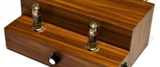
Hi all! I would like to share my experience in manufacturing a tube amplifier using 6N1P + 6P14P. Since I am just a beginner radio amateur and do not have the appropriate education and experience in working with electronics, please do not judge strictly! Recently I have become interested in electronics, I decided to try my hand at creating a sound amplifier, at first I looked closely at transistor circuits, but I always wanted a tube amplifier so that I would have something to show off to my guests.
It was based on the Datagor article “Tube UMZCH on 6N3P+6P14P? It's simple! Printed circuit board included" Thank you very much for the diagram and explanations, since the diagram turned out to be quite feasible for me.
Power transformer design
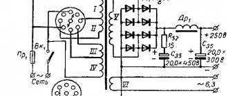
The amplifier's power transformer is assembled on a core made of USH-30 plates, the thickness of the set is 60 mm. The location of the transformer windings is shown in Fig. 67. The output transformer was made on the same core as the power one. IN
All layers of the secondary winding of the output transformer are connected in parallel and contain the same number of turns. Winding data of transformers are given in the table.
| Designation according to the diagram | Number of turns | Number of layers in the winding | The wire |
| Tr1 | |||
| 1-2 | 430 | 7 | PEV-1 0.55 |
| screen | — | 1 | PEV-1 0.25 |
| 4-5 | 380 | 5 | PEV-1 0.41 |
| 6-7 | 375 | 5 | PEV-1 0.41 |
| 8-9-10 | 122×2 | 2 | PEV-1 0.25 |
| 11-12-13 | 13×2 | 2 | PEV-1 1.08 |
| Tr2 | |||
| 1-2 | 270 | 3 | PEV-1 0.41 |
| 3-4 | 60 | 1 | PEV-1 0.64 |
| 5-6 | 60 | 1 | PEV-1 0.64 |
| 7-8 | 270 | 3 | PEV-1 0.41 |
| 9-10-11 | 180 | 2 | PEV-1 0.41 |
| 12-13 | 270 | 3 | PEV-1 0.41 |
| 14-I5 | 60 | 1 | PEV-1 0.64 |
| 16-17 | 60 | 1 | PEV-1 0.64 |
| 18-13 | 270 | 3 | PEV-1 0.41 |
AMPLIFIER ON 6P14P LAMP
Recently I was asked to build a simple tube amplifier that could produce about five watts of power and drive both speakers and low-impedance headphones. Having searched the Internet for a suitable circuit, I decided to assemble such a device.
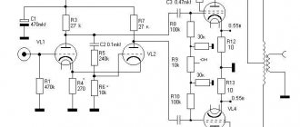
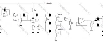
Above is a schematic diagram of only one channel of a tube amplifier, the second channel is similar. In the circuit, capacitors were introduced into the cathode automatic bias circuits: C4 and C7 for lamps VL1 and VL2, respectively, in order to eliminate the influence of cathode resistors on the output resistance of the stages. As a result, introducing capacitor C7 into the cathode circuit of the 6P14P output pentode made it possible to slightly increase the maximum output power. The output stage uses a triode connection, in which the shielding grid is connected directly to the anode, which ensures deep local feedback in terms of voltage.
If you do not find a 6P14P lamp, which is found in any old tube TV, then it can be replaced with a 6P15P or 6P18P. The lamps differ only in the nominal voltage at the anode, which for 6P18P is 170 V with a maximum allowable 250 V. However, 6P18P works great at higher voltages and can be installed instead of 6P14P without any changes in the circuit. The 6P43P lamp can only be used by replacing the cathode resistor with a 300-400 Ohm one. Select more accurately based on the anode current.
The input preamplifier tube is 6N3P, replaced by 6N26P. 6N2P and 6N23P are also suitable, but with slightly worse results. For convenience, installation is carried out on a printed circuit board made of fiberglass, the drawing of which can be drawn in sprint-layout format. More experienced radio amateurs can assemble ULF using classical technology - mounted mounting.
As the basis for the power supply of this ULF, I took a transformer from some kind of tube device, which provides an anode current of 120 mA at a voltage of 200 V. The circuit diagram and drawing of the board are below.
Naturally, after the rectifier, the voltage will rise. The power filter capacitor can be taken at 300 microfarads or higher. If possible, then set it to at least 1000. To eliminate background penetration through the filament filament of the input lamp, a special chain R12 - R15 is used, which supplies it with a positive potential. The finished tube amplifier is placed in a metal case, and the beauty lamps are brought out in cylinders. Author: fez.
Tube ULF Forum
- TUBE ULF FOR 6P14P AND 6N2P
- SE TUBE AMPLIFIER
- SUPER QUALITY 10 W AMPLIFIER
- NUTUBE 6P1 TUBE AMPLIFIER
Schematic diagram
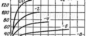
All amplifier stages are made using tubes. Maximum undistorted output power is 100 W at 8 ohm load resistance. Amplifier sensitivity at a maximum output power of 1.5 V. Nonlinear distortion coefficient at an output power of 80 W at a frequency of 1000 Hz - 0.5%. Operating frequency range from 20 Hz to 50 kHz with frequency response unevenness of 3 dB.
Rice. Schematic diagram of a powerful tube ULF with an output power of 100 Watts.
The amplifier is powered by an AC mains voltage of 220 V, background level -76 dB. The first stage of the amplifier is made on the left triode of lamp L1. A bass reflex cascade is assembled on the right triode of this lamp.
The connection between the lamp triodes is direct. This made it possible to eliminate self-excitation of the amplifier at low frequencies of 1...5 Hz. For the same purpose, as well as to reduce nonlinear distortions, a correction circuit C3, R5 is included in the cathode circuit of the left triode of lamp L1, compensating for frequency distortions introduced by transition capacitors and leakage resistors in the control grid circuits of the phase inverter and output stages of the lamps. To eliminate the background alternating current, a positive voltage of +25 V is supplied to the filament circuit of the amplifier lamps from the divider R21, R19.
After the bass reflex, the signal is amplified by lamp L2. The resistances of the resistors in the anode circuits of the triodes of this lamp are selected so as to obtain the maximum undistorted voltage on the control grids of the output lamps.
The final stage of the power amplifier is assembled using a push-pull circuit using lamps L3 and L4. To simplify the design of the output transformer, the resistance between the anodes of the lamps should be as small as possible. And since it depends on the amplitude of the alternating voltage at the lamp anodes and on the amplitude of the anode current, it is recommended to work with large current amplitudes.
The maximum anode current for 6RZS lamps is obtained at a supply voltage of the shielding grids of 270 V and an anode supply voltage of 540 V. The lamps in one cylinder are connected in parallel. The ultra-linear connection of the lamps made it possible, with the same maximum output power, to obtain less nonlinear distortion and lower output resistance compared to tetrode connection.
To reduce nonlinear distortion, the entire amplifier is covered by deep negative feedback of about 20 dB. Possible self-excitation of the amplifier at higher frequencies (50-200 kHz) is eliminated by negative feedback, the voltage of which is removed from the anode of lamp L2 and from the output of the amplifier and through capacitors C10 and C14 is supplied to the cathode circuit of the left triode of lamp L1.
The grid circuit of this lamp includes resistor R2, which, together with the input capacitance of the lamp, forms a voltage divider, which also reduces the likelihood of self-excitation of the amplifier at high frequencies if part of the output signal reaches the amplifier input through the mounting capacitance.
Simple tube power amplifier for 14-20 Watts (6N2P, 6P14P)
Comments (22): #1 root March 07 2016 +6
The circuit has some similarities with those presented in the publication “Low Frequency Amplifiers” by V. Bolshov in Radio magazine for 1960, number 7.
Here in the article the author does not indicate the winding data of the inductor L1, we present them from a similar circuit of the power source: the inductor is designed for a current of 100-120 mA, it is made on a core made of USH16 plates, the thickness of the set is 24 mm, the inductor winding contains 1600 turns of PEL-0 wire, 2. (Radio 1973, 03).
#2 Mikhail November 21 2016 +9
Due to the fact that there is not much tube household radio equipment left, it is better not to waste it on worthless homemade products, but to buy new radio tubes and transformers in a store, or ready-made amplifiers in China, and restore and preserve audio equipment from the USSR.
#3 march November 21 2016 +16
Well, not much, but who foresaw the situation. I put everything I needed aside, sorted it and eat it... enough for my crafts... a lamp in kg.,. ts, tv, dr, tvk,... they lie and wait for their time...
#4 Sergey December 12 2016 +7
Resistor R17, intended for setting the background minimum, should not be 100 kOhm, but 100 Ohm!
#5 Alexander May 29 2022 +4
Tell me, what is the standard size of the sh85 transformer core? I can't find anything about them((
#6 root May 30 2022 +13
Hello. A mention of the Sh85 transformer iron was found in the audioportal.hi-fi.ru forum archive, the dimensions are as follows:
- Middle plate - 28.3mm;
- Magnetic path length - 17cm;
- Set - 4cm.
Ш85 - armored magnetic circuit for a transformer, assembled from a set of Ш-shaped plates.
The resulting picture is:
Here are two useful articles on making transformers yourself, including from sets of w-shaped plates:
- How to independently assemble a transformer from W-shaped plates.
- How to make and wind a transformer with your own hands.
#7 Alexander July 05 2022 +5
Please tell me about the correct winding of the output transformer according to this circuit. I see the diagram and table, but it’s not clear where to start and how to proceed.
#8 root July 05 2022 +7
Alexander, the winding circuit for the output transformer is not quite simple, I’ll try to describe it in detail. Let’s assume that winding to the right means holding the frame in your hands and winding the wire towards you, and to the left - away from you.
- We wind sections A+B (350+350) towards ourselves (right) with a wire with a cross-section of 0.2 mm, mark the starting wire as 1. Upon completion of winding, bend the wire in the opposite direction, fix it so that the winding does not unravel. Now we wind the windings V+G (450+250) with the wire away from us (left).
- We wind sections Z+G (350+350) in the direction away from us (left) with a 0.2mm wire, mark the starting wire as 3. Then we bend and fix the wire, wind sections E+D (450+250) with the wire towards us (right) .
- We connect the ends of the resulting windings together and mark them as 2.
- We wind sections I+K (80+80) in the direction away from us (left) into two wires with a cross-section of 0.2 mm at once, marking the beginning of winding as 5. After the start of winding, we solder them together, and do the same with the ends.
- We wind sections L+M (190+190) in the direction away from us (left) into two wires with a cross-section of 0.47 mm each. We solder the beginnings together and mark them as 6. We also solder the ends together and solder them to the ends of the I+K sections, mark them as 4.
It may seem that the configuration of windings 1-2 and 2-3 is the same - this is not true, they cannot be wound in two wires at once.
As for winding sections I+K and L+M into two wires at once - perhaps this is not a very good solution and here you still need to wind each winding separately.
Just in case, once again carefully check the manual I wrote with the data given in the article.
#9 Leonid April 14 2022 +3
What is the voltage in the circuit?! The article says that capacitors must be designed for a voltage of at least 50 volts, but nothing is said about the supply voltage.
#10 root April 14 2022 +5
Comment #1 provides very similar circuits of tube UMZCHs for 6N2P and 6p14P. Their anode power supply is 320V.
At the output of the rectifier (Fig. 1), on capacitor C8, there should be 320V.
The article indicates voltages for electrolytic capacitors - no less than 350V. Those that can be installed with a voltage of 50V - there are only two of them: C3 and C6.
#11 Sergey July 04 2022 +4
I assembled a tube stereo amplifier using this circuit, and I was very pleased with the sound. Although the amplifier is rather weak, it is still powerful enough to drive the Radio Engineering S-90 (4 Ohm). I didn’t wind the output transformers; I took ready-made TorPP-15(4/8) from Istok.
The maximum anode voltage of this amplifier is 300 volts. If you give more, the anodes of the pentodes begin to overheat and turn red. The pentodes themselves also need to be paired (I experienced a dip in the low-frequency region with poorly selected lamps).
Instead of an electromagnetic choke in the anode circuit, it is better to install an electronic one. In terms of manufacturing price, it is not more expensive, but the voltage is more stable and the anode voltage is supplied smoothly upon startup. I made the choke according to the scheme https://r-lab.narod.ru/drossel01.htm, only I increased the input capacitance four times, and made two stabilizers, since I have a stereo amplifier.
The filament was powered from 12 volts, lowered to the required 6.3 volts using two DC-DC converters on the XL4005 chip (one per channel). This PWM controller has the lowest ripple level and handles a load of 5 amps.
Thanks to the author of this diagram!
#12 LevaK August 29 2022 +1
I doubted the winding data of the power transformer. According to the description, the 220V network winding has 1000 turns, i.e. 4.5 turns/volt. The step-up winding for powering the anode circuits has 1300 turns. 1300: 4.5 = 289 V. This is the voltage at the output of the transformer. After rectification, the first filter capacitor will have 289 x 1.4 (this is the square root of two) = 400 V. The 350 V capacitors will be broken. And the voltage for the output lamps is very high, according to the passport no more than 300V at the anode and 250V at the second grid. It will be bad for the lamps.
#13 Sanya November 11 2022 +4
Hello, anyone who doubts the functionality of the scheme, I can assure you that it works and very, very well. Nothing superfluous in circuit design and a very rich sound (I listen to it on a homemade TQWP speaker, on a 5gd-1ppr speaker. I also tried it on other speakers, I was not disappointed.) Power from 14 to 20 watts, depending on the load rating. I checked! The output transformer is simple; it doesn’t do anything with the windings, that is, on itself, on itself. The trans iron was taken from the UPS tr-ra along with the frame. I wound 2800 turns with 0.27mm wire with a tap from the middle. I wound the secondary with 0.41mm wire, three in parallel and connected it - it turned out to be 1.2mm. (first 91 vit. secondary - insulation (masking tape), 750 vit. primary - each layer is insulated!, again 91 vit. secondary - insulation, 750 vit - brought out the middle output - 750 vit., again 91 vit. secondary and 550 or 500 vit primary. Why not 750? Because during the winding process, the diameter of the coil increases, and, accordingly, the length of the wire, which is proportional to the increase in its resistance. In this way, I equalized the resistance in both arms of the trance - the total was 156 Ohms, one arm 77 Ohms, the other 79 Ohms. I advise you to check the transformer after winding resistance with a multimeter and rewind (rewind) the required amount.I am very picky about good sound and I can say with confidence that this amplifier sounds very decent (if assembled correctly).
#14 odissey November 26 2022 +4
What nonsense is this in the description? What is 20 W into an 8 ohm load? 6P14P - 5 W power, two in a clock cycle in the pentode at a load of 4 Ohms will produce 10 W, you can squeeze out 12, but with distortion. Further. For a 1.25 wire, the permissible current is 2.5 A. That is, work is at the limit. The power winding is complete nonsense, but it’s ridiculous to even talk about a day off. The “specialist” who is “picky about good sound” does not consider the turns, which play the main role, but the resistance. If you care about the accuracy of the shoulder resistance, smart people put a cheek in the middle of the frame, in other words, divide the frame into two and wind it sectionally and frame by frame. This is the best option. The funny thing is that if someone, after reading the description and recommendations of a “specialist”, actually puts together a diagram using this data…. By the way, the scheme is classic, it is 100 years old, it has been repeated (with minor deviations) hundreds of times. Yes, also, in the anode 325 is a bit too much, 300 is just right, the lamp is pumped up and works without overload, the anode does not overheat. Yes, I almost forgot. For a RR 2800 with a tap from the middle - this is complete crap, at least 3600. For the RR on 6P14P on transaxles from TCA 70, I wound 4040 by 2022 turns in the arm and this was done according to the formulas, as it should be to wind outputs. A 0.27 wire is definitely not needed there (look at the anode current and select the wire cross-section according to the diagram) 0.2 - for your eyes.
#15 Stark December 13 2022 +2
Hello. What kind of inductor should be in this circuit?
#16 root December 13 2022 +1
Hello. If you are talking about the L1 throttle, then read the first comment.
#17 Stark December 17 2022 +1
And another question is what the output transformer should be.
#18 root December 17 2022 +3
The output transformer is homemade, its data and winding diagram are given in the article.
#19 Stark December 18 2022 +3
Is it possible to install TVZ 1-9 instead of a homemade transformer?
#20 ra1qea May 05 2022 +1
root, the amplifier circuits of G. Poptsov and V. Bolshov differ in the bass reflex. Don't you see this?
#21 root May 06 2022 0
They are not identical, but are simply given as an example with the source indicated, so that there is where to look for the missing data for the BP. The second circuit has a tone control, which, if desired, can be an addition to the circuit in Fig. 1. The phrase “very similar” has been removed. Thank you.
#22 sanich1969 December 07 2022 0
ra1qea, the phase inverter circuits in all three circuits are absolutely the same and identical! It’s strange that you don’t see this!