SE or single-ended circuits are amplifiers in which the signal is amplified by one amplifying element (tube, transistor) in series at each stage. These systems operate in pure Class A and are valued by many audiophiles for their good microdynamics and precision in detail presentation. Simplicity is also an advantage. The disadvantages of these circuits are: low energy efficiency (Class A), low gain, slightly higher distortion. We present here a prototype of such an amplifier.
It is supposed to be a simple and cheap system that can be built with minimal electronics experience. Typically the most expensive part of a tube amplifier is the speaker transformers, power transformers, and tubes. Therefore, to reduce costs, we suggest using acoustic transformers from an old tube TV (you will need two). In such a TV you will also find radio tubes, more powerful resistors, and some high-voltage capacitors will also come in handy.
The tubes needed to create this amplifier can also be obtained by disassembling an old radio. Network transformers can be wound or purchased. Of course, this is not a Hi-End amplifier, but a simple amplifier for beginners, but the sound will already be noticeably different from “silicon”. Although the sound quality in tube amplifiers is highly dependent on the speaker transformers. The small transformers offered for assembly, used in tube TVs, do not have very good frequency parameters. A really good transformer is large, heavy and quite expensive.
List of elements
Amplifier
- R1, R1A - 1 kOhm,
- R2, R2A - 470 kOhm,
- R3, R3A - 150 kOhm,
- R4, R4A - 1-1.5 kOhm,
- R5, R5A - 150-200 kOhm
- R6, R6A - 470 kOhm,
- R7, R7A - 1 kOhm,
- R8 - 500-1000 Ohm, adjust the grid current so that it does not exceed 5 mA,
- R9, R9A - 120-180 Ohm, select to obtain the required cathode current,
- R10, R10A - 5-20 kOhm,
- R11 - 10-20 kOhm,
- P - 2×47 kOhm / logarithmic,
- C1, C1A - 100 µF / 16 V,
- C2, C2A - 100-220 nF / 250 V,
- C3 - 100 nF / 400 V,
- C4 - 47 uF / 400 V,
- C5, C5A - 100 µF / 25 V,
- C7 - 33-100 pF, choose so that it does not cut off high frequencies and the oscilloscope signal is correct,
- C6, C6A - about 1 nF / 250 V soldered directly to the speaker transformer outputs.
power unit
- R101 - 400-1000 Ohm / 5 W,
- R102, - 3-5 kOhm / 1 W,
- R103 - 270 kOhm / 0.5 W,
- R106 - 0.8-1.5 kOhm so that the LED shines brightly enough,
- R104, R105 - 100 Ohm,
- C101 - 100 nF / 400 V, C102, C103, C104, 105 - 100 µF / 400 V,
- C106, C107 - 47 uF / 400 V,
- M1 - diode bridge rectifier 5-10 A / 600 V,
- power transformer 220 V / 250 V - 0.15 A, 6.3 V - 2.5 A.
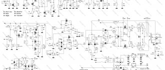
The scheme is very simple. The figure shows one channel, the other is identical. The input signal is fed through potentiometer P to low-power triodes (L1), operating in a common-cathode circuit. After amplification, the pentode (L2) is fed through capacitor C2. The loudspeaker transformer (its anode winding) is the load for this lamp. The secondary windings of the transformer allow you to power a speaker or headphones.
The amplifier is surrounded by a negative feedback loop, which reduces distortion and broadens the frequency response. However, this is done at the cost of amplification. Feedback is taken from the output of the transformer speaker and is supplied through resistor R10 to the cathode of the first lamp (L1). Capacitor C7 is used for possible phase correction. Capacitors C3, C4 and resistor R11 form a filter to prevent excitation of the amplifier. A similar role is played by resistors R1 and R7 in the lamp grid circuits.
The L2 radio tube can operate in two modes - pentode and triode. Pentode mode is more powerful, with more distortion. Triode mode is less efficient but has less distortion. Changing the operating mode can be done with resistor R8. In triode mode it should have a small value - usually 100 Ohms. If we want to use the pentode mode to operate the amplifier, we connect R8 as shown in the diagram. You can give a higher value, but so that the current flowing through grid 2 is slightly less than 5 mA. Typically the resistor value is 500-1000 ohms.
To connect loudspeakers, you need a transformer that will change the high voltage in the anode circuit to match the impedance of the speakers or headphones. Popular and easy-to-get transformers from an old tube TV are ideal for this purpose. Naturally you will need two, one per channel.
You can experiment with other lamps, instead of 6P14P use more powerful pentodes (for example 6L6 or others), but remember that this requires changing the supply voltage, the power transformer must also have more power. The values of the elements that determine the operating point of the lamp must also be selected accordingly, and the AC transformers must be adapted to the type of lamp. Circuits of such amplifiers can be easily found on our website.
Contents
- 1 Schematic diagram of one amplifier channel
- 2 Inlet filter - why?
- 3 Amplifier power supply
- 4 Design and details
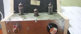
- 5 The appearance of the amplifier mounted on the board is shown in the photograph
- 6 Setting up an amplifier is not difficult.
- 7 Precautions
- 8 Working on mistakes
- 9 Circuit diagram 2
- 10 About scheme 2
- 11 Signet v.2
- 12 About heating capacitors
- 13 About replacing lamps
- 14 Sources used
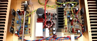
Amplifier power supply
The power supply is also not complicated. The anode voltage is rectified using a bridge and filtered by an RC filter consisting of resistors R101-R102 and capacitors C101-C107. Resistor R108 discharges high-voltage capacitors after turning off the power.
Resistors R105, R104 balance the filament voltage to ground, so the network noise heard in the speakers should be minimal. Resistor R101 gets quite hot, so for better heat dissipation it can be placed on a small radiator, or two can be connected at once - in series or in parallel (by selecting the resistance of individual resistors accordingly). This power supply provides power to both ULF channels simultaneously.
After switching on, the amplifier must warm up for several minutes so that the currents flowing through the lamps stabilize. Resistors R101 and R102 in the power supply, as well as R9 and R9A on the lamps, will heat up to a high temperature, this is normal. However, if there is a smell of scorched varnish in the air and we see that the paint on one of the resistors changes color, then the resistor has too little reserve. In this case, it should be replaced with one of the same rating, but with more power. After a longer period of operation, we again check the supply voltage and the voltage drop across the cathode resistors of the lamps. We correct the anode currents of lamp L2 (L2A).
↑ Working on bugs
The time that has passed since the assembly of the first working prototype of the UMZCH has once again shown that, in principle, there is no design that cannot be improved. If for each change in the circuit it was necessary to make a new amplifier, then probably at least half of the city’s population would be “happy” with them. However, this is a hyperbole :-) In reality, several changes in the circuit were tested, facilitating the “more correct” use of lamps, but without requiring significant modifications to the design.
↑ Recommendations for manufacturing
As mentioned above, iron with a thickness of 0.8-1.0 mm was used for the chassis.
The front, rear, side panels, top and bottom covers are made of sheet material 0.6-0.8 mm thick. On top of the front panel there is a decorative overlay made of sheet aluminum 1 mm thick. A switch and volume control resistor are mounted on the front panel. On the rear panel there is a network connector, a power fuse block, a connector for connecting speakers and input connectors. There are two input connectors - one is SG5 type and the other is a pair of bell type. They are parallelized and are used for easy connection of various types of cables. Reamers were made and cut out on graph paper for all metal parts. Then, using adhesive tape, the reamers were attached to a sheet of metal and marks were made with a core in the right places for future holes. Then ALL future holes were drilled with a drill with a diameter of 1-1.2 mm. And only then are the parts bent.
Don’t be lazy to bend each part according to your own, simplest mandrel - a sheet of plywood of the required dimensions and 10 mm thick. The accuracy of manufacturing parts in this case reaches 0.5-1.0 mm. Which is pretty good for a home design. There are practically no nuts in the design. Holes for threaded connections were made with a punch to increase the thickness of the thread. To cut out all the metal panels, I highly recommend purchasing a grinder with 125 mm circles. I even cut plywood frames for it. It really stinks when you're sawing, but you can bear with it in the garage... I'm not giving details of other parts of the body - let everyone do it to their own taste!
↑ Sources used
1. A. A. Kovalev. Entry-level tube UMZCH. - AK Laboratory Workshop, 2002 2. F. I. Tarasov. Circuits of amateur low-frequency amplifiers. - Mass Radio Library, M. 1957 3. Arthur Frundzhyan. Acrobatics of tube cascades. - Magazine “Class A”, 1997, No. 7. 4. D. S. Gurlev. Handbook of electronic devices. - “Technology”, Kyiv, 1966 5. M. Kireev. Amateur Radio High-End. 40 best designs of lamp UMZCH for 40 years. “Radioamator”, Kyiv, 1999
↑ About heating capacitors
Many have noticed that during operation of the amplifier, the electrolytic capacitors heat up. Heating occurs due to thermal radiation from the lamps and, in my opinion, is not at all dangerous - capacitors C3 and C6 heat up to a temperature of about 40-45 degrees, which is quite a bit. However, it should be noted that the layout of the amplifier's printed circuit board is designed for an open structure and, if the amplifier mounted on the proposed printed circuit board is placed in any housing, it is possible that heat shields will have to be used to reduce the degree of heating of the capacitors.
Limit operating data of 6P14P lamps
| Name | 6P14P | 6P14P-V | 6P14P-EV | 6P14P-ER |
| Filament voltage, V | 5.7 − 7 | 5.7 − 7 | 5.7 − 7 | 6 − 6,6 |
| Anode voltage, V: | ||||
| — with a power dissipation of more than 8 W | 300 | 300 | 300 | 300 |
| - with power dissipation less than 8 W | 400 | − | 400 | − |
| - with the lamp locked | − | 500 | 500 | 500 |
| 2nd grid voltage, V | 300 | 300 | 300 | 300 |
| Same with the lamp locked, B | − | 500 | 500 | 500 |
| Voltage between cathode and heater in 6P14P lamps, V | 100 | 200 | 200 | 200 |
| Cathode current (average value), mA | 65 | 65 | 65 | 65 |
| Power dissipated by the anode, W | 14 | 14 | 14 | 14 |
| Power dissipated by the 2nd grid, W | 2,2 | 2 | 2 | 2 |
| Resistance in the 1st grid circuit, MOhm | 1 | 1 | 1 | 1 |
| Temperature of 6P14P lamp cylinder, °C | − | 300 | 300 | 300 |
| Ambient temperature of 6P14P lamps, °C | −60…+70 | −60…+70 | −60…+70 | −60…+200 |
↑ Details
The design uses constant resistances of the MLT 0.5 and MLT 2 types. Transition capacitors of the MBM type.
If there are better ones, you can use them too. You can dispense with capacitor C1, but since the author likes DC isolation, he left C1. Drawings of all printed circuit boards and developments of metal parts are presented in CorelDraw files below. Printed circuit boards are drawn in two layers: the first is conductors, the second is drawings of parts. To obtain only conductors, it is enough to disable printing of the second layer. The boards are already drawn in a mirror image and are ready for trying on in “laser-iron technology”. Since enough space was left for the tubes (the experience of previous developments was taken into account), the thermal regime of the amplifier turned out to be very favorable.
Setting up
Setting up the amplifier begins with checking the lamp mode in accordance with table. 1 (voltages on the electrodes of the lamps were measured using a voltmeter with an input resistance of 5 kohms, V).
| Lamp designation | Anode voltage | Screen grid voltage | Offset voltage |
| L1 (left triode) | 75 | — | — |
| L1 (right triode) | 125 | — | -1,5 |
| L2 | 260 | 260 | -9,0 |
| L3 | 260 | 260 | -9,0 |
After this, using a sound generator and an output meter or a tube voltmeter, the frequency characteristics of the amplifier are measured at various positions of the tone controls.
They should approximately correspond to those shown in Fig. 2. If at lower frequencies the rise is small, then it can be increased by increasing the capacitance of capacitor C9 or reducing the resistance R16.
The depth of adjustment at lower frequencies is selected by changing the capacitance of capacitor C„. Decreasing R3 compared to R2 also increases the depth of adjustment, however, decreasing R3 reduces the input impedance of the amplifier, which is not always possible, for example, when working with a piezoelectric pickup.
The necessary limits for adjusting the frequency response of the amplifier at higher frequencies are determined by selecting the capacitance of capacitor C1.
The position of the potentiometer R12 slider is based on the minimum background at the amplifier output. It should be noted that the capacitance of capacitors C4 and C8 can be reduced to 20-30 μF without a significant increase in background.
In a properly assembled and adjusted amplifier, the background level does not exceed 46 dB (the background voltage on the voice coil is 12 mV).
Yu. Mikhailov. Radio 1958, No. 8.
↑ About scheme 2
First of all, on the strong recommendations of real audiophiles, capacitors were introduced into the cathode automatic bias circuits: C4 and C7 for lamps VL1 and VL2, respectively.
Thanks to these capacitors, the influence of cathode resistors is eliminated (in fact, local current feedback is eliminated) on the output resistance of the amplifier stages (without these capacitors it is noticeably higher). And, if for the stage on VL1 this does not manifest itself so clearly, then the introduction of capacitor C7 into the cathode circuit of the output pentode VL2 made it possible (albeit very slightly) to increase the maximum output power of the amplifier. The chain for supplying the general OOS (R4, R7) to the cathode circuit of the first lamp (R5, C4) is somewhat complicated. This was done in connection with the desire to reduce the influence of the parameters of this chain on the mode of the VL1 lamp. Now the bias voltage of the lamp VL1 is almost completely determined by the resistance value of the cathode resistor R5, as a result of which there is no need to select it after changing the feedback depth.
Another two-position jumper JP2 has been introduced, increasing the degree of convenience for those who like to experiment. The jumper allows you to switch the output of the lamp from pentode mode to triode mode and vice versa. (The diagram shows a pentode connection - when the shielding mesh is connected to a power source. In a triode connection, the shielding mesh is connected directly to the anode, which ensures a fairly deep local feedback in voltage, while the current-voltage characteristics - I-V characteristics - of the lamps become very similar to the I-V characteristics of triodes , which is why this name arose.) It should be noted that using this feature requires special care from the experimenter - changing the lamp mode often leads to the need to correct the displacement value on the first grid, which means that it is also necessary to change the value resistance R10.
Limit operating data of 6P14P lamps
| Name | 6P14P | 6P14P-V | 6P14P-EV | 6P14P-ER |
| Filament voltage, V | 5.7 − 7 | 5.7 − 7 | 5.7 − 7 | 6 − 6,6 |
| Anode voltage, V: | ||||
| — with a power dissipation of more than 8 W | 300 | 300 | 300 | 300 |
| - with power dissipation less than 8 W | 400 | − | 400 | − |
| - with the lamp locked | − | 500 | 500 | 500 |
| 2nd grid voltage, V | 300 | 300 | 300 | 300 |
| Same with the lamp locked, B | − | 500 | 500 | 500 |
| Voltage between cathode and heater in 6P14P lamps, V | 100 | 200 | 200 | 200 |
| Cathode current (average value), mA | 65 | 65 | 65 | 65 |
| Power dissipated by the anode, W | 14 | 14 | 14 | 14 |
| Power dissipated by the 2nd grid, W | 2,2 | 2 | 2 | 2 |
| Resistance in the 1st grid circuit, MOhm | 1 | 1 | 1 | 1 |
| Temperature of 6P14P lamp cylinder, °C | − | 300 | 300 | 300 |
| Ambient temperature of 6P14P lamps, °C | −60…+70 | −60…+70 | −60…+70 | −60…+200 |
Anode characteristics of 6P14P-EV
Final tests
We won’t talk about the sound itself, because we don’t know any cool audiophiles. But after using the amplifier for several months, we can assure you that 2 x 5 W of continuous power for the speakers is enough to cover even a large room, provided that you are not a fan of powerful bass. As for the purity and softness of sound, TDA microcircuits generally remain modestly on the sidelines!
↑ Signet v.2
The printed circuit board was modified taking into account the above changes. It was possible to maintain its previous size and mechanical parameters. But since the installation has become denser, during assembly you need to pay attention to the dimensions of the electrolytic capacitors used. The version of the printed circuit board with the JP2 jumper, however, seems not entirely successful due to the excessive number of additional conductors, which significantly increases the installation density (the voltage between the jumper contacts can reach 300 Volts - so you need to be careful about maintaining the gap between the board tracks to avoid breakdown).
Printed circuit board without JP2 in high resolution (click on the button to expand to full screen)
Printed circuit board with JP2 in high resolution (click on the button to expand to full screen)
↑ Design of the output audio transformer
The transformer is wound on PL iron.
The thickness of the tape winding is 20 mm, the width of the tape is 30 mm. Window dimensions 60 mm by 20 mm. The primary windings are wound with wire with a diameter of 0.17 mm, the secondary windings - 0.5 mm. The transformer consists of two identical coils, the winding order on each coil is as follows: _______ frame _______ tracing paper _______ 250 vit Ø 0.17 _______ tracing paper _______ 250 vit Ø 0.17 _______ paper _______ 90 vit Ø 0.5 Section A _______ paper _______ 250 vit Ø 0.17 _______ tracing paper _______ 250 vit Ø 0.17 _______ paper _______ 45 vit 2 x Ø 0.5 (wind in two wires) Section B _______ paper _______ paper _______ 250 vit Ø 0.17 _______ tracing paper _______ 250 vit Ø 0.17 _______ paper _______ 90 vit Ø 0.5 Section B _______ paper _______ 250 vit Ø 0.17 _______ tracing paper _______ 250 vit Ø 0.17 _______ paper _______ paper _______ Cardboard with output lamellas _______ varnished cloth In total, the primary winding is 2 × 2000 turns. Ordinary wrapping paper was used as interwinding insulation. It turned out to be quite dense and tough. When operating on loads of 4 and 16 Ohms, sections A, B are used, and for an 8 Ohm load, sections A, B and B are used. The order of connections of the sections of the primary and secondary windings is shown in the following figure.
Connecting sections of the output transformer
On the left is a diagram of the connections of the sections of the primary winding, on the right is the secondary for an 8 ohm load. H1a, K1a - the beginning and end of the first section of the primary winding on one coil, H1b, K1 b - the beginning and end of the first section of the primary winding on the second coil. For secondary windings - 1a and 3a, respectively, sections A and B. A 2a - section B.