At the beginning of the 21st century, vinyl became fashionable again. Its sales are increasing, artists are releasing new albums on black discs with pieces of paper in the middle, electronics manufacturers are pushing new models of record players into our noses.
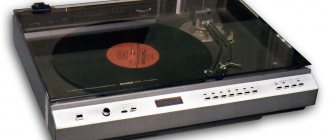
I began to wonder, what is so unique about this medium? What would it be like to listen to him? How-how, buy a player and records. I see Vega EP-110. Vega... It was through this brand of radio tape recorder (Vega-335) that I began to get acquainted with music in my distant childhood. It was a good radio, and even from the first batch. There is a headphone output and a GZM105-MD pickup installed by the previous owner. Hmm, let's try!
Contents
- 1 The beginning of the story
- 2 Work plan
- 3 Reviving the EPU 3.1 Engine
- 3.2 Passik
- 3.3 Photoresistor
- 3.4 Strobe
- 3.5 Tonearm
- 6.1 Parts List of Headphone Amplifier (Single Channel):
↑ Beginning of the story
I brought it home and got hold of a couple of layers. I turned it on, the needle slid along the track, and a characteristic light crackling sound was heard in the headphones. Soooo, let's build up the speed. What's happened? Sometimes slower, sometimes faster. OK. More or less got it right, now turn up the volume. Oh my god, the potentiometers are broken in some places! At full volume there is background. Moreover, the varnish on the body has turned yellow, and now it is not quite silver in color. Of course, you could buy another device. But then I remembered a phrase from a Datagor article about a tweak of the Vega-122 amplifier: “an engineer who cannot fix a faulty Vega is, in general, not one.” Although I have a different specialty, not in any way related to electronics, the thought “challenge accepted, I’ll still make this capricious young lady” stuck firmly in my head.
↑ Useful links
⚡Berd Radio website today ⚡Additions to the Arctur-006 player from Leonid Ridiko (Belarus) ⚡Repair of the G-1001 (G-602) EPU from Alexander Sheiko (Ukraine) ⚡Unitra G600B on rt22.ru That's
all for now. The next final part will describe the assembly and configuration of the player. Thank you for your attention! To be continued.
↑ Reviving the EPU
↑ Engine
Remove the support disk, belt, impeller and press “start”.
Is the engine making a loud noise? No luck, his place is in the trash, we are looking for a donor for transplantation. Just growls? Great, the patient will live. We unsolder the wires going to the engine from the contact strip. I apologize, I didn’t take a photo of this process, I got too carried away. We make a mark on the body and the lid (they will need to be aligned), and carefully pry the lid off with a scalpel or flat screwdriver. It is important to be careful as the screwdriver can come off and cause injury. There are brass brushes on the engine cover that need to be bent a little to the side (1 mm is more than enough) so that they slide along the current collector contacts in a different place.
There may be burrs between the contacts themselves that need to be removed with a gypsy needle. The bearings need to be generously lubricated with silicone grease, or with a spindle. Now you can put it back together; the cover can be pressed in using carpentry clamps. We put the engine in place. Turn it on.
If it growls, then you can drop silicone oil into the gap between the shaft and the housing. A couple of drops of it are needed to lubricate the spindle shaft. The spindle itself must be cleaned of old grease using alcohol and a cloth.
↑ Passik
Next, remove the belt and measure its length when folded. I had 235 mm, which means its place is in the trash. The length of the new one is 220 mm.
↑ Photoresistor
Checking the photoresistor. The resistance of the illuminated one should be about 2 kilo-ohms. More? We put a new one in the bucket. I installed FPF-7A.
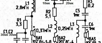
The remaining improvements to the EPU control system are shown in the diagram: instead of a half-wave rectifier there is a diode bridge (any 400V, 1A), C9 is shunted with a “film” of 0.22 microns, instead of R15 there is now a 7810 stabilizer, screwed to the chassis through a mica spacer in place of the D5 zener diode. It is better to replace the RF diodes with 1N4148 (KD522) (D2, D3, D6, D9).
Light bulb Z2 changes to a red LED with a current-limiting resistor. (see diagram) T4 is now placed on a small radiator, and C1 has been replaced with a film one for a voltage of 400 V (they didn’t find 10 kV in the store, hee hee).
The EPU was collected and checked after each stage of refinement, and after the performed procedures for prevention and modification of nutrition, the speed no longer floats; Moreover, now I don’t need to set it again on my Vega every time I turn it on. List of parts:
Diode bridge 400V 1A - 1 piece, Capacitor 0.22mFx63V - 1 piece, Capacitor 2.2mfx63V - 1 piece, Stabilizer 7810 - 1 piece, Diodes 1N4148 (KD522) - 4 pieces.
↑ Strobe
Another trouble with the EPU is the dim strobe lamp, which makes it difficult to adjust the speed by marks in bright light or during the day. To do this, I removed the cover of the sroboscope, shook out its original intestines, and soldered a diode bridge with a canopy, to the output of which a blue LED was connected. The bridge is connected to the secondary, which powers the EPU through a 3.3k, 1W resistor.
Parts list:
R1 - 3.3k, 1W - 1pc, VDS1 - 1N4007 - 4pcs HL1 - 5mm super bright LED in any color of your choice.
The containers are of high quality; according to repairmen, they have never been found to be dry, which means there is no point in changing them. Although I changed some of mine. Variable P5 may need to be replaced with a new one, trimming resistors P1, P2 could have oxidized, so we check them and, if necessary, change them. Mine were fine. Assemble the turntable, click “Start”. The speed may fluctuate for 10 seconds - the instructions generally indicate the need for a 5-minute warm-up - then it returns to normal. Maniacs can install a heavy support disk from Unitra G-602 (Vega 106, 108), but I did not notice any significant changes in the operation of the ECU.
↑ Tonearm
I replaced the wiring in the tonearm with a regular Soviet installation wire with a cross section of 0.07 mm square.
in fluoroplastic insulation. To do this, I had to remove the tonearm tube (but the bearings can be lubricated). The hardest part is getting the end of the wire out of the small hole at the end of the tube. For convenience, I used a bent pin. The wires are soldered to the pad as before. The shielded cables running from it to the ECU board in the trash bin only pulled the “ground”. A shielded cable is soldered to the block and goes directly to the corrector. Thus, mute keys that spoiled the sound were removed from the path. The “color markings” of the wires were made using scraps of insulation from different colored wires. It's all here. Let's move on.
↑ Tonearm Maintenance
Considering the garage storage of the player by the previous owner, the tonearm (like the entire player) was in a deplorable state: the head was missing, the shell was damaged, the tube was oxidized, everything was dusty and dirty.
Therefore, the tonearm was completely disassembled. Next, the plastic base was washed with soap and water. The end result was like new:
The tonearm axis rests on two cone-cup bearings. The cups are cleaned of any remaining old grease (if any) and installed in the mounting holes in the base of the tonearm:
Lubricant is applied to the inner surface of the cups. As such, I used silicone grease SI-180
.
It should be noted that I consulted about the lubricants used with specialists from the Berdsk Radio Plant on the website https://vega-brz.ru.
So, SI-180 grease was approved for lubrication of tonearm bearings. Next, the balls are placed in the cup:
The number of balls per cup is 11 pcs. The diameter of the balls is 2.5 mm.
Next, the cone on the tonearm axis is also cleaned and re-lubricated. The axle is carefully inserted into the hole in the support (so that the balls do not spill out). On the reverse side, the balls of the second bearing are placed in the lubricated cup, and a counter cone is put on the axle.
When installing the axle, the frame should be oriented correctly - the side pin should be on the installation side of the anti-skating lever:
Next, a plastic protective washer is installed on the axle and the fixing nut is screwed on. The tightening force of the nut and the play of the tonearm are set according to the ¼ rule: the nut is tightened until the first signs of resistance to rotation appear, after which the nut is turned in the opposite direction by ¼ turn. If a large backlash occurs, it means that the bearing is worn out and its cone part needs to be replaced. After setting the required tightening force, the locknut is screwed on for final fixation.
All that remains is to install the hitchhiking flag on the vertical axis. First, install the flag itself, then the spring washer and the adjusting plate. When installing the adjusting plate, it is necessary to align the flat on the axle with the corresponding place in the hole of the plate, and install the adjusting screw into the hole in the flag. The entire “sandwich” is secured with a square nut. The axis of horizontal movement of the tonearm is ready!
You can immediately install the anti-skating lever. It is installed in a special recess in the tonearm support and secured with a special pin:
You can also install a microlift here. It is installed in two holes in the support, a spring is placed on the bottom of the rod and secured with a locking ring. A few words about microlift damping: damping liquid, if necessary, is placed in the gap between the rod and the bronze bushing of the microlift
It is recommended to use PMS 250000 as a damping fluid. My microlift works properly, so I won’t do anything. And I don’t have PMS 250,000!
Let's move on to the vertical movement node. Let's start with the tonearm tube. The tube is made of aluminum (or some kind of aluminum alloy), and the years had not been kind to it - it was all covered with oxidation stains. Diamond polishing paste and a piece of felt helped bring the tube's appearance back to its original state. As a result, the surface received an almost mirror-like shine.
We begin assembly by laying the head signal wires inside the tube
Then the vertical movement unit is installed on the rear end of the tube and secured with a screw. This screw also secures the contact tab for grounding the tonearm tube.
After this, the head wires are threaded through the hole in the vertical axis, and the tube with the bracket is installed in the frame of the vertical axis. Vertical bearings are lubricated
and the horizontal axis is fixed with adjusting screws on the sides of the frame. The tightening force of the adjusting screws and backlash are also set according to the ¼ rule. For final assembly of the tonearm, all that remains is to install the tailpiece and shell. The shank is installed in the guides on the tonearm vertical movement bracket and tightened with an adjusting screw.
This screw moves the tonearm shank along with the counterweight in a horizontal plane, which ensures static balancing of the tonearm. We will consider this process in detail later during the final setup of the tonearm. We screw the counterweight onto the shank, and the back of the tonearm is ready! We put the shell on the front end of the tube and fix it with a screw.
It should be noted that the original shell from my turntable was damaged - the side handle was broken off - but I was lucky enough to purchase the original one as a replacement.
That's it, the tonearm is ready!
↑ Replacing the pickup head
The standard version is MF-100.
Reviews about her are not very good. Therefore, it is better to change immediately. I already had a GZM-105MD, as mentioned earlier. But it was replaced with an Audio Technica AT95E pickup. Modern heads are light, so you need to either make the shell heavier (as I did) in order to set the required clamping force (for this head 1.5-2.4g), or sculpt another shell there. I weighted it down with 2 thin plastic strips glued with cyanoacrylate. In a past life it was some kind of card.
Next you need to set the downforce. To do this, I turned on the microlift and rotated the counterweight until the tonearm became parallel to the ECU table (when viewed from the side). I turned the plastic scale zero up. I spin it up to 1.7g.
We put it according to the template. You can download them on the Internet or draw them yourself. I downloaded mine online, but, alas, I couldn’t find the link. It's a pity.
↑ Installation of Target Light
I was prompted to make this modification by an article about modifications to the Arcturus-006 player.
Immediately follows about is not so necessary, but it helps a lot when choosing tracks on a record when the player is used in a place with insufficient lighting. Besides, all sorts of Technics and others like them put Target Light on their turntables, but why are we any worse? Nothing, let's go! Apart from any extravagant designs, Target Light is usually made in two main ways. The first one is more complicated, but looks more elegant. Target Light is a column that is recessed into the player body. To use it, you need to click on the button located nearby or on the column itself. In this case, the column rises to the level of the plate and the backlight turns on. This design, for example, is found in the Target Light of the Technics SL-1200 player, as well as in similar models of Audio-Technica, Pioneer and other players.
This column has a rather complex internal structure due to the lifting/lowering mechanism. Therefore, making something similar at home is not impossible, but quite problematic. So let's look at the second main design of the Target Light. Here the light bulb is housed in a small cylindrical housing with an RCA connector at the end.
On the top panel of the player there is simply a mating RCA connector into which a cylinder with a light bulb is inserted. A similar solution was used in younger Audio-Technica models, as well as in less legendary players such as Stanton, Numark and the like.
This design is much easier to implement, so let’s do it.
So, first we need the basic elements - RCA connectors. I had a socket (“mother”) with a mount on the body, but I had to buy a “father”. Here the audio signal will not leak, so we don’t need to buy gold-plated connectors boiled at dawn in the tears of a virgin. We take something more or less decent in appearance and move on. I used these:
Next, you need to make some additional parts in order to get a mini lamp from the audio connectors. Firstly, the socket is secured with a regular nut, which is not very presentable. We need something more aesthetic. Secondly, we disassemble the “dad” and throw away the body. Instead, you need to make a cylinder with a hole for the lamp. After some thought, the following parts were designed and manufactured:
And this is what the connectors look like assembled:
2 ultra-bright white LEDs with a diameter of 3 mm will be used as a light source. The LED housings have a flat on the cathode side. On one LED, you need to use a file or sandpaper to make the same flat on the anode side.
Then you need to glue these two LEDs together, aligning their cathode to the anode. The two middle pins are soldered together, and thin wires are soldered to the outer ones. The other ends of the wires are soldered to the pins of the RCA connector.
Next, both parts of the column are assembled together, and thus the working part of the Target Light is obtained.
The socket is installed on the EPU table in a convenient place so that the column does not interfere with the movement of the tonearm and the disc with the record.
The LEDs will be powered from 10V from the ECU control board. The connection is made according to the following scheme:
↑ Power supply
Time has not spared the tiny capacities, and as a result - the background. It was decided to make a new power supply unit. The scheme is simple and does not require explanation. The rectifier is assembled using ultrafast UF4007, shunted with 0.033 µF capacitors to suppress high-frequency interference. Next is a smoothing filter and a voltage stabilizer made on unregulated stabilizers 7815, 7915.
The dimensions of the board were chosen so that the new power supply could easily replace the old one. The schematic diagram is attached. I don’t give the PP - I drew it directly with a marker on the textolite, without LUT. The diagram is simple; drawing a PP yourself will not be difficult; You can also use the factory one. Board dimensions 50x95mm. PSU parts:
VD1-4 - UF4007 - 4 pcs, you can install Schottky or any ready-made bridge for 1-2 Amps C1-C4 - 33 nF x 63 V - 4 pcs C5-C6, C9-C10 - 1000 mF x 25 V - 4 pcs C7 -C8 — 0.47 mF x 63 V — 2 pcs C13-C14 — 1 mF x 63 V — 2 pcs VR1 — 7815 — 1 pc VR2 — 7915 — 1 pc R1-R2 — 51 Ohm, 0.25 W — 2 pcs
↑ New headphone amplifier
I didn’t like the separate volume control by channel, as well as the DIN5 socket, which forced me to have an additional adapter. Since headphones are usually taken out of the closet/shelf/drawer before listening, they are hidden there after listening. “I opened my wallet, took out my purse, closed my wallet...” I didn’t like the sound of the factory amplifier made on the K157UD2 op amp. On the same Network, A. Vorobyov’s diagram from the collection “Designs and diagrams for reading with a soldering iron” was found and repeated. Volume 5", pp. 163-169. Solon Press, 2004.
The diagram was drawn by Datagor.
Original source of the circuit: Headphone Amplifier - redcircuits.com The amplitude swing of the input voltage is assigned to the TL071 op-amp. VT1-VT2 in the diode connection, together with resistors R3-R4, set the bias for the transistors of the output stage assembled on transistors VT3-VT4. The amplifier has a pleasant sound, minimal noise, and the ability to operate at loads from 32 to 600 Ohms. I added “films” to the power supply for better sound in the midrange and high frequencies.
↑ Headphone amplifier parts list (single channel):
OP1 — TL071 — 1 piece R1 — 20 k (dual, respectively, one for two channels) R2 — 560 Ohm — 1 piece R3-R4 — 10 k — 2 pieces R5 — 12 k — 1 piece R6-R7 — 2.2 Ohm — 2 pieces R8 — 22 Ohm, 0.5 W — 1 piece C1, C6-C7 — 1 mF x 63 V — 3 pieces C2, C4-C5 — 100 mF x 25 V — 3 pieces C3 — 22 mF x 25 V — 1 piece C8 — 22 pF — 1 piece VT1-VT3 — BC337 — 2 pieces VT2-VT4 — BC327 — 2 pieces VR1 — 7815 — 1 piece VR2 — 7915 — 1 piece
The factory socket for the amplifier controls was redone. The holes are sealed at the back with plastic “patches” cut from the case for the IC. The plastic must be sanded. Narrow strips of plastic were cut into the slots along the volume controls and glued on top of the main plugs in 2 layers, which eliminated the need for putty. Everything was glued to cyanoacrylic. After drying, it was sanded and painted with what was at hand (paint a la blued iron).↑ Amplifier-corrector
Or a phono stage or a vinyl stage, a phono preamp, whatever your heart desires.
In Vega 110 it is installed in a metal screen, made on the K157UD2 microcircuit. I unscrew the screw and remove the screen cover. What the??? The capacitor values do not match the diagram! C9-C10 cost 3.3nf instead of 10nf, and C13-C14 cost 0.15uF instead of 0.25uF. No, that's not the case. We change the Soviet film to MKP. Electrolytes C3-C4 must also be changed. Listening after replacing the capacitors was not particularly impressive. The sound is too soft. I unsolder K157UD2, along with it the capacitors of the op-amp correction circuits C7-C8. TL071 operational amplifiers in a DIP8 package were chosen as a replacement. Why exactly them, and not the two-channel version TL072? Yes, because they can be soldered without any adapters!
We take one microcontroller, bend pins 1 and 8 there so that they are parallel to the body. We solder it so that pins 4 and 5 take the place of 7 and 8 of the standard op-amp, respectively. The output and inverting/non-inverting input are where they belong. For the second op-amp, we also bend legs 1 and 8, solder them on the side of the conductors so that the 4th leg takes the place of the 1st, and 5 takes the place of the 14th. I ran the power to pins 4 (-) and 7 (+) with thin wires from the corresponding tracks on the board.
It was possible to etch a new board to fit modern sockets, install a cooler corrector - it’s a matter of taste. I was curious to squeeze all the juice out of the standard scheme. Collected and listened. The sound became richer, but just as soft. Apparently, it's not a matter of details, but of circuit design.
↑ Engine check and maintenance
Before starting the engine after long-term storage in unfavorable conditions, it is advisable to check its condition: brushes, lubricant, etc. To do this, it is necessary to remove the engine itself from the plastic housing. Loosen the clamping screw on the impeller bushing and remove the impeller from the shaft
The motor is in a silicone casing and sits tightly in the housing. We remove it from the housing by pressing on it from below through the hole in the housing. After removal, the engine should be disassembled. The engine cover is pressed very tightly into the metal housing. To disconnect them, you can place a knife on the line between the body and the lid and lightly hit the knife. After a gap appears, use a small flat-head screwdriver to carefully pry the cover around the perimeter and separate it from the body.
IMPORTANT!
Before disassembling the engine, be sure to mark the position of the cover relative to the housing with a marker or scratch. When assembling, it is necessary to accurately align the marks on the cover and body. Otherwise, you are guaranteed to have a fun life in the form of all sorts of problems with the engine, from loss of power and rotation in the opposite direction to complete inoperability.
After disassembly, remove the rotor and inspect all parts for contamination, oxidation, etc.
We clean everything with alcohol, remove old grease from the bushings and rotor shaft, and, if necessary, clean the armature contact tracks and brushes from oxides and contaminants. Apply new grease to the bushings. I used the same silicone grease SI-180
. You can also use “Device” or “Household Lubricant” liquid oil. Make sure that oil does not get on the contact parts of the armature and brushes.
Next, carefully insert the rotor into the bushings, align the marks on the cover and housing, and assemble the engine by pressing the cover into the housing. We put the silicone casing on the engine and insert it into the plastic case. All that remains is to replace the photoresistor. We remove the old one and make sure that it is faulty. And again we have the same problem with the dimensions of the mounting socket and the new photoresistor as in the ECU board. To securely position and fix the new photoresistor in the huge socket, I also had an adapter sleeve machined out.
This bushing has a small flat. Without it, the bushing would rest against the engine and would not fit into the socket. When installing, it is necessary to point the flat towards the engine and press the bushing all the way into the socket. Next, we put the impeller on the shaft and secure it with a clamping screw.
The engine is ready!
We attach the LED for illuminating the engine photoresistor in a standard bracket in the same way as the auto-stop LED on the ECU board.
↑ Bringing beauty to the exterior
At first I just wanted to cover the body with self-adhesive film, but, knowing how to work with wood, it would be unforgivable to do so.
I remove the EPU, the body, and remove the legs from it. Just for fun, I scraped the cycles a little. Under five layers of varnish/paint/varnish/paint/varnish (well, it stinks) lies ordinary birch plywood. The ends are covered with beech veneer. This could have simply been scraped off, sanded and varnished. But the beech veneer has already peeled off from below. No, do it - do it like that. Oak veneer was cut from an old board. Thickness - 3.5 mm “dirty”. After sanding it will be 2.5-3mm. The beech flew off on its own when touched by a chisel. I removed 2 mm from the top of the case with a milling cutter.
The veneer was glued with PVA glue, each piece was clamped with clamps through a block. It was glued in the following sequence: the upper edges adjacent to the sides of the control unit, then the edge under the control unit, the side edges and the front edge. Before gluing each next one, it was necessary to cut off the excess from the previous one. Oak is a fragile wood and cracks easily. Therefore, I left 1 mm of “extra” and simply “gnawed” it off with sandpaper, which gave beautiful and smooth ends.
After all the edges were covered, I sanded the body with sandpaper No. 150 and No. 320, tinted with cherry stain and coated with water-based brush varnish. I really didn’t want to create a stink in the apartment. Before varnishing, the wood was stained and sanded several times, since stain raises the wood fibers. Afterwards the device was assembled in the usual sequence.