Calculation and winding of a pulse transformer
Today I will talk about the procedure for calculating and winding a pulse transformer for the power supply on ir2153.
My task is the following: I need a transformer with two secondary windings, each of which must have a tap from the middle. The voltage value on the secondary windings should be + -50V. The current will flow 3A, which will be 300W.
Calculation of a pulse transformer.
First, download the Lite-CalcIT and run it.
We select the conversion circuit - half-bridge. Depends on your switching power supply circuit. In the article “Switching power supply for a 300W IR2153 bass amplifier,” the conversion circuit is half-bridge.
We indicate the supply voltage is constant. Minimum = 266 Volts, Nominal = 295 Volts, Maximum = 325 Volts.
We indicate the controller type ir2153, generation frequency 50 kHz.
There is no output stabilization. There is no forced cooling.
The diameter of the wire, indicate the one that is available. I have 0.85mm. Please note that we indicate not the cross-section, but the diameter of the wire.
We indicate the power of each of the secondary windings, as well as the voltage on them. I indicated 50V and a power of 150W in two windings.
The rectification circuit is bipolar with a midpoint.
The voltages I indicated (50 Volts) mean that two secondary windings, each of which is tapped from the middle, and after rectification, will have + -50V relative to the middle point. Many would think that if they indicated 50V, it means that relative to zero there will be 25V in each arm, no! We will get 50V in each leg relative to the middle wire.
Next, we select the core parameters, in my case it is “R” - a toroidal core, with dimensions 40-24-20 mm.
Click the “Calculate!” button. As a result, we obtain the number of turns and the number of cores of the primary and secondary windings.
Winding a pulse transformer.
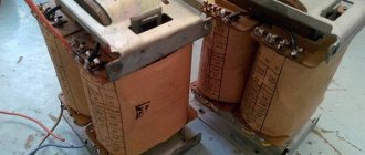
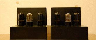
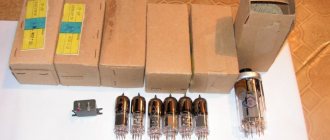
So, here is my ring with dimensions 40-24-20 mm.
Now it needs to be insulated with some kind of dielectric. Everyone chooses their own dielectric; it can be varnished cloth, rag tape, fiberglass, or even tape, which is best not to use for winding transformers. They say adhesive tape corrodes the enamel of the wire, I cannot confirm this fact, but I found another disadvantage of adhesive tape. In the case of rewinding, the transformer is difficult to disassemble, and the entire wire becomes covered in glue from the tape.
I use Dacron tape, which does not melt like polyethylene at high temperatures. Where can I get this lavsan ribbon? It’s simple, if there are stumps of shielded twisted pair, then by disassembling it you will get a Mylar film approximately 1.5 cm wide. This is the most ideal option; the dielectric turns out to be beautiful and of high quality.
We glue the lavsan to the core with tape and begin to wrap the ring in a couple of layers.
Next, we wind the primary, in my case 33 turns with two wires of 0.85 mm diameter (I played it safe). Wind it clockwise as shown in the picture below.
We twist and tin the leads of the primary winding.
Next, we put a few centimeters of heat shrink on top and heat it up.
The next step is to again insulate a couple more layers with a dielectric.
Now the most “misunderstandings” and many questions begin. How to wind? One wire or two? Should I put the winding in one layer or in two layers?
During my calculation, I received two secondary windings with a tap from the middle. Each winding contains 13+13 turns.
We wind two wires in the same direction as the primary winding. As a result, there were 4 outputs, two outgoing and two incoming.
Now we connect one of the outgoing terminals to one of the incoming terminals. The main thing is not to get confused, otherwise you will end up connecting the same wire, that is, short-circuiting one of the windings. And upon startup, your switching power supply will burn out.
Connect the beginning of one wire to the end of the other. Tinned. Put on the heat shrink. Next, wrap it again with lavsan film.
Let me remind you that I needed two secondary windings; if you need a transformer with one secondary winding, then this is the end. We wind the second secondary winding in the same way.
Then we wrap the top again with lavsan film so that the outer winding fits tightly and does not unwind.
As a result, we got this neat bagel.
Thus, it is possible to calculate and wind any transformer, with two or one secondary winding, with or without a center tap.
Pulse transformer calculation program Lite-CalcIT
Article on rewinding a pulse transformer from a PC power supply .
Calculation of a pulse transformer for a push-pull converter and matching devices
In a properly designed push-pull converter, there is no direct current through the winding and no core bias. This allows you to use a full magnetization reversal cycle and get maximum power. Since the transformer has many interdependent parameters, the calculation is carried out step by step, clarifying the initial data if necessary.
How to determine the number of turns and power?
The overall power obtained from the condition of not overheating the winding is equal to [1]:
Pgab = So ⋅ Sc ⋅ f ⋅ Bm / 150 (1)
Where: Pgab - power, W; Sc is the cross-sectional area of the magnetic circuit, cm2; So is the area of the core window, cm2; f—oscillation frequency, Hz; Bm = 0.25 T - permissible induction value for domestic nickel-manganese ferrites at frequencies up to 100 kHz.
We select the maximum power of the transformer as 80% of the overall power:
Pmax = 0.8 ⋅ Pgab (2)
The minimum number of turns of the primary winding n1 is determined by the maximum voltage on the winding Um and the permissible core induction Bm:
n1 = (0.25 ⋅ 104 ⋅ Um) / (f ⋅ Bm ⋅ Sc) (3)
The dimensions of the units here are the same as in formula (1).
The current density in winding j for transformers with a power of up to 300 W is taken to be 3..5 A/mm2 (higher power corresponds to a lower value). The wire diameter in mm is calculated using the formula:
d = 1.13 ⋅ ( I / j )1/2 (4)
Where I is the effective winding current in A.
Example 1:
An ultrasonic installation requires a step-up transformer with a power of 30..40 W. The voltage on the primary winding is sinusoidal, with an effective value of Ueff = 100 V and a frequency of 30 kHz.
Let's choose a ferrite ring K28x16x9.
Its cross-sectional area: Sc = (D - d) ⋅ h / 2 = (2.8 - 1.6) ⋅ 0.9 / 2 = 0.54 cm2 Window area: So = π ⋅ (d / 2)2 = π ⋅ ( 1.6 / 2 )2 = 2 cm2 Overall power: Pgab = 0.54 ⋅ 2 ⋅ 30 ⋅ 103 ⋅ 0.25 / 150 = 54 W Maximum power: Pmax = 0.8 ⋅ 54 = 43.2 W Maximum voltage at winding: Um = 1.41 ⋅ 100 = 141 V Number of turns: n1 = 0.25 ⋅ 104 ⋅ 141 / ( 30 ⋅ 103 ⋅ 0.25 ⋅ 0.54 ) = 87 Number of turns per volt: n0 = 87 / 100 = 0 .87Effective value of the primary winding current: I = P / U = 40 / 100 = 0.4 ACurrent density we choose 5 A/mm2. Then the copper wire diameter: d = 1.13 ⋅ ( 0.4 / 5 )1/2 = 0.31 mm
How can I determine the current density?
If we are making a low-power transformer, we can play with the current density and choose thinner wires without fear of overheating. In Eranosyan’s book [2, Page 109] the following tablet is given:
| Pn, Tue | 1 .. 7 | 8 .. 15 | 16 .. 40 | 41 .. 100 | 101 .. 200 |
| j, A/mm2 | 7 .. 12 | 6 .. 8 | 5 .. 6 | 4 .. 5 | 4 .. 4,5 |
Why does current density depend on the power of the transformer?
The amount of heat released is equal to the product of the specific losses and the volume of the wire. The dissipated amount of heat is proportional to the area of the winding and the temperature difference between it and the environment. As the size of the transformer increases, the volume grows faster than the area, and for the same overheating, the specific losses and current density must be reduced. For transformers with a power of 4..5 kVA, the current density does not exceed 1..2 A/mm2 [3].
3. How to clarify the number of turns of the primary winding?
Knowing the number of turns of the primary winding n, we calculate its inductance. For a toroid it is determined by the formula:
L = μ0 ⋅ μ ⋅ Sс ⋅ n2 / la (5)
Where: Area Sc is given in m2; average length of the magnetic line la in m; inductance in H; μ0 = 4π ⋅ 10-7 H/m - magnetic constant.
In engineering form, this formula looks like this:
L = AL n2 (5A), n = ( L / AL )1/2 (5B)
The AL coefficient and the power parameter So ⋅ Sc for some types of rings are given in Table 2 [4,5,6]:
| Ring | K7x4x2 | K10x6x3 | K10x6x4.5 | K16x10x4.5 | K20x12x6 | К32х20х6 | K38x24x7 | K40x25x11 |
| AL, nH/vit2 ± 25% | 224 | 310 | 460 | 430 | 620 | 570 | 650 | 1050 |
| So ⋅ Sc, cm4 | 0,004 | 0,017 | 0,025 | 0,106 | 0,271 | 1,131 | 2,217 | 4,050 |
For the transformer to operate as a matching device, the following condition must be met:
L > ( 4 .. 10 ) ⋅ R / ( 2 ⋅ π ⋅ fmin ) (6)
Where L is the inductance in H; R = U2eff / Pn load resistance reduced to the primary winding Ohm; fmin — minimum frequency, Hz.
In key converters, two currents flow in the primary winding of the transformer: rectangular load current Ipr = Um / R and triangular magnetization current of the winding IT:
For normal operation of the converter, the value of the triangular component should not exceed 10% of the rectangular component, that is, the inductance of the winding must satisfy the inequality:
L>5 R/f (7)
If necessary, the number of turns is increased or ferrite with a higher μ is used. It is not advisable to overestimate the number of turns in the winding. Due to the increase in interturn capacitance, resonant oscillations may occur at the operating frequency.
The selected ferrite must have sufficient maximum induction and low losses in the operating frequency band. As a rule, at low frequencies (up to 1 MHz) ferrite with μ = 1000 .. 6000 is used, and at radio frequencies it is necessary to use materials with μ = 50 .. 400.
Example 2:
The transformer from Example 1 is wound on a K28x16x9 ring made of nickel-manganese ferrite 2000NM with magnetic permeability μ = 2000. Load power P = 40 W, effective voltage of the primary winding Ueff = 100 V, frequency f = 30 kHz. Let's clarify the number of its turns.
Reduced load resistance: R = 1002 / 40 = 250 Ohm Cross-sectional area of the magnetic circuit: Sc = 0.54 cm2 = 0.54 ⋅ 10 -4 m2 Average length of the magnetic line: la = π ( D + d ) / 2 = π ( 2, 8 + 1.6 ) ⋅ 10 -2 / 2 = 6.9 ⋅ 10 -2 m Inductance coefficient: AL = 4π ⋅ 10-7 ⋅ 2000 ⋅ 0.54 ⋅ 10 -4 / 6.9⋅10-2 = 1966 nH/vit2
Minimum inductance of the primary winding according to formula (6): L = 10 ⋅ 250 / (2π ⋅ 3 ⋅ 104) = 13.3 mH Number of turns: n = (13.3 ⋅ 10 -3 / 1.963 ⋅ 10 -6) 1/2 = 82
It is even less than that calculated earlier in Example 1 nmin = 87. Thus, the condition of sufficient inductance is met and the number of turns of the primary winding is n = 87.
What ferrites can be used and why?
As is known, the core in a transformer acts as a concentrator of electromagnetic energy. The higher the permissible induction B and the magnetic permeability μ, the greater the density of the transmitted energy and the more compact the transformer. The so-called ones have the greatest magnetic permeability. ferromagnets - various compounds of iron, nickel and some other metals.
The magnetic field is described by two quantities: intensity H (proportional to the winding current) and magnetic induction B (characterizes the force action of the field in the material). The relationship between B and H is called the magnetization curve of a substance. In ferromagnets, it has an interesting feature - hysteresis (Greek: lagging) - when the instantaneous response to an influence depends on its background.
After leaving the zero point (this section is called the main magnetization curve), the fields begin to run along a certain closed curve (called a hysteresis loop). Characteristic points are marked on the curve - saturation induction Bs, residual induction Br and coercive force Hc.
Fig.1. Magnetic properties of ferrites. On the left is the shape of the hysteresis loop and its parameters. On the right is the main magnetization curve of 1500NM3 ferrite at various temperatures and frequencies: 1 - 20 kHz, 2 - 50 kHz, 3 - 100 kHz.
Based on the values of these quantities, ferromagnets are conventionally divided into hard and soft. The former have a wide, almost rectangular hysteresis loop and are good for permanent magnets. And materials with a narrow loop are used in transformers. The fact is that there are two types of losses in the transformer core - electrical and magnetic. Electrical (for excitation of Foucault eddy currents) are proportional to the conductivity of the material and frequency, but magnetic ones are smaller, the smaller the area of the hysteresis loop.
Ferrites are pressed powders of iron oxides or other ferromagnetic materials sintered with a ceramic binder. This mixture combines two opposing properties - the high magnetic permeability of iron and the poor conductivity of oxides. This minimizes both electrical and magnetic losses and allows transformers to be made that operate at high frequencies. The frequency properties of ferrites are characterized by the critical frequency fc, at which the loss tangent reaches 0.1. Thermal - Curie temperature Tc, at which μ abruptly decreases to 1.
Domestic ferrites are marked with numbers indicating the initial magnetic permeability and letters indicating the frequency range and type of material.
The most common is low-frequency nickel-zinc ferrite, designated by the letters NN. It has low conductivity and a relatively high frequency fc. But it has large magnetic losses and a low Curie temperature.
Nickel-manganese ferrite is designated NM. Its conductivity is greater, so fc is low. But magnetic losses are small, the Curie temperature is higher, and it is less afraid of mechanical shocks.
Sometimes ferrites are labeled with an additional number 1, 2 or 3. Usually, the higher it is, the more temperature stable the ferrite is.
What brands of ferrites are we most interested in?
Thermally stable ferrite 1500NM3 with fc=1.5 MHz, Bs=0.35..0.4 T and Tc=200 ℃ is good for converter technology.
For special applications, ferrite 2000NM3 is produced with standardized desacammodation (temporary stability of magnetic permeability). It has fc=0.5 MHz, Bs=0.35..0.4 T and Tc=200 ℃.
Ferrites of the NMC series have been developed for powerful and compact transformers. For example, 2500NMS1 with Bs=0.45 T and 2500NMS2 with Bs=0.47 T. Their critical frequency is fc=0.4 MHz, and their Curie temperature is Tc>200 ℃.
As for the permissible induction Bm, this parameter is adjustable and is not standardized in the literature. Approximately we can consider Bm = 0.75 Vsmin. For nickel-manganese ferrites this gives approximately 0.25 T. Taking into account the drop in Bs at elevated temperatures and due to aging, in critical cases it is better to play it safe and reduce Bm to 0.2 T.
The main parameters of common ferrites are summarized in Table 3:
| Brand | 100NN | 400NN | 600NN | 1000 NN | 2000 NN | 2000 Nm | 1000 NM3 | 1500 NM1 | 1500 Nm3 |
| μstart | 80..120 | 350.. 500 | 500.. 800 | 800.. 1200 | 1800.. 2400 | 1700.. 2500 | 800.. 1200 | 1200.. 1800 | 1200.. 1800 |
| fc, MHz | 7 | 3,5 | 1,5 | 0,4 | 0,1 | 0,5 | 1,8 | 0,7 | 1,5 |
| Tc, ℃ | 120 | 110 | 110 | 110 | 70 | 200 | 200 | 200 | 200 |
| Bs, T | 0,44 | 0,25 | 0,31 | 0,27 | 0,25 | 0,38.. 0,4 | 0,33 | 0,35.. 0,4 | 0,35.. 0,4 |
How hot will the core get?
Losses in magnets.
At a frequency less than critical fс, energy losses in the magnet consist mainly of losses due to magnetization reversal, and eddy current losses can be neglected.
Experience and theory show that energy losses per unit volume (or mass) during one magnetization reversal cycle are directly proportional to the area of the hysteresis loop. Therefore, the power of magnetic losses:
PH = P0 ⋅ V ⋅ f (8)
Where: P0 – specific losses per unit volume (measured at frequency f0 with induction B0); V – sample volume.
Table 4. Specific volumetric losses in ferrites 2500NMS at f0 = 16 kHz; B0=0.2 T:
| T, oC | P0, μW/(cm 3⋅Hz) | |
| 2500NMS1 | 2500NMS2 | |
| 25 | 10,5 | 8,5 |
| 100 | 8,7 | 6 |
However, with increasing frequency, the saturation induction decreases, the hysteresis loop is deformed, and losses increase. To take these factors into account, Steinmetz (CP Steinmetz, 1890-1892) proposed an empirical formula:
PH = P1 ⋅ m ⋅ ( f / f1 ) α ( B / B1) β (9)
It was agreed [7, Page 54] that f1 = 1 kHz, B1 = 1 T. The values of P1, α, β and core mass m are indicated in the reference book.
Table 5. Specific losses in some ferrites
| Brand | 1500NM3 | 2000NM1-A,B | 2000NM3 | 2000NM-17 | 3000 NM-A | 6000NM-1 | |||
| f | — | 0.4..100 kHz | 0.1..1 MHz | — | 0.4..100 kHz | 0.1..1 MHz | 0.4..200 kHz | 20..50 kHz | 50..100 kHz |
| P1, W/kg | 23,2 | 32±7 | 13±3 | 44,6 | 63±10 | 25±4 | 48±8 | 11±2 | 38±0,8 |
| α | 1,2 | 1,2 | 1,4 | 1,3 | 1,2 | 1,4 | 1,2 | 1,35 | 1,6 |
| β | 2,2 | 2,4 | 2,7 | 2,85 | 2,76 | 2,69 | 2,6 | ||
Copper losses.
Ohmic losses in the primary winding at room temperature and without taking into account the skin effect:
PM1 = I2 eff ( ρ / Sm ) ( ( D - d ) + 2h ) ⋅ n1 (10)
Where: Ieff - effective current, D - external, d - internal diameter of the ring, h - its height in meters; n1—number of turns; Sm - cross-section of the wire, in mm2; ρ = 0.018 Ohm ⋅ mm2 / m - resistivity of copper.
Total losses in all windings at elevated ambient temperatures:
PM = ( PM1 + PM2 + .. )⋅ ( 1 + 0.004⋅ ( T — 25oC ) ) (11)
Total losses in a transformer.
Magnetic and copper losses:
PΣ = PH + PM (12)
Estimated overheating temperature during natural convection:
ΔT = PΣ / ( αm Sool ) (13)
Where αm = (10..15) -4 W/(cm2oС), Sool = π /2 ( D2 - d2 ) + π h ( D + d )
Example 3:
Let's find the losses in the transformer from Examples 1 and 2. For simplicity, we assume that the secondary and primary windings are the same.
Effective current of the primary winding Ieff = 0.4 A.
Copper losses of the primary winding: PM1 = 0.42 ⋅ (0.018 / 0.08) ⋅ (28 - 16 + 18) ⋅ 10 -3 ⋅ 87 ≈ 0.1 W.
Copper losses of both windings: PM = 0.2 W.
According to reference data for ferrite 2000NM P1 = 32 W / kg; α = 1.2; β = 2.4; the mass of the K28x16x9 core is 20 grams.
Ferrite losses: PH = 32 ⋅ (30 / 1) ⋅ 1.2 ⋅ (0.25 / 1) ⋅ 2.4 ⋅ 20 ⋅ 10 -3 = 1.36 W
Total losses in the transformer: PΣ = 1.56 W.
Approximate efficiency = (40 - 1.56) / 40 ⋅ 100% ≈ 96%
How to take into account the inertial properties of a transformer?
In Fig.2. shows the T-equivalent circuit of the transformer. It includes the source resistance ri, the reduced load resistance R = n2 Rн or R = Pн / U2eff, where n = U1 / U2 is the transformation ratio, Ueff is the effective voltage of the primary winding.
Fig.2. Transformer equivalent circuit.
The inertial properties of the transformer are determined by the small leakage inductance Ls, the magnetizing inductance Lμ (almost equal to the inductance of the primary winding L1), the parallel winding capacitance Cp (the so-called dynamic capacitance) and the series capacitance between the windings Sp.
How to evaluate inductance and capacitance?
L1 is calculated using formula (5) or measured experimentally. According to [8], the leakage inductance in order of magnitude is equal to Ls ~ L1 / μ. The capacitance Cp is approximately 1 pF per turn.
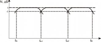
The transformer works like a bandpass filter. At low frequencies it is a high-pass filter with a cutoff frequency ωн = R / Lμ. At high frequencies, elements Ls and Cp form a low-pass filter with a cutoff frequency ωв ≈ (Ls Cp)-1/2. The series capacitance Cn is small and has practically no effect on operation.
The model has two characteristic resonances:
Low-frequency (magnetization resonance) in a parallel circuit Lμ Average. Its frequency is fμ ≈ ( 1/ 2 π ) ⋅ ( Lμ Cp )-1/2 , and its quality factor Qμ ≈ ( ri || R ) ⋅ ( Lμ / Cp )-1/ 2 (14)
High-frequency (scattering resonance) in the circuit formed by Ls and Cр. Its frequency fs ≈ ( 1/ 2 π ) ⋅ (Ls Cp )-1/2, and its quality factor Qs ≈ ( Ls / Cp)1/2 / ri (15)
How do winding resonances affect?
The amplitude-frequency response of the transformer is similar to the frequency response of a bandpass filter, but at its upper edge the resonance fs gives a characteristic peak.
The response to voltage pulses depends on the method of switching on the source and the resistance values of the circuit.
With a low internal resistance of the source ri, only resonance fs appears in the form of a characteristic “ringing” at the pulse fronts. If the source is connected through a switch, then when it is opened, intense oscillations with a frequency fμ may occur.
Fig.3. An example of frequency response and transient process in a transformer. Its equivalent circuit is given below in Figure 4.
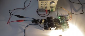
Experimental measurement of pulse transformer parameters.
For the sample, a ring of 3000NM ferrite of size K10x6x2 was taken. The primary winding was 21 turns; secondary 14; transformation ratio n = 1.5; load resistance was 4.7 kOhm; The source was a rectangular pulse generator on TTL microcircuits with a level of 6V, a frequency of 1 MHz and an internal resistance of ri ≈ 200 Ohms.
Let's calculate the theoretical parameters:
Sc = 4 ⋅ 10 -6 m2, la = 25.13 ⋅ 10 -3 m, ALtheor = 600 nH/vit2, L1theor = 0.6 ⋅ 212 = 265 µH, Ls theor ≈ 265/3000 = 0.09 µH, Cp theor ≈ 21+14 = 35 pF. Reduced load resistance R = n2 Rн = 2.25 ⋅ 4.7 ~ 10 kOhm.
Results of inductance measurements using the AKIP-6107 device:
L1 = 269 µH, L2 = 118 µH, short-circuiting the secondary winding we get 2Ls = 6.8 µH, which is two orders of magnitude higher than its theoretical estimate.
The dynamic capacitance Cp can be estimated using formula (15) by applying rectangular pulses to the transformer and using an oscilloscope to measure the period of “ringing” oscillations at the pulse fronts at the output of the secondary winding. The “ringing” frequency fs turned out to be 18.5 MHz, which gives Cp ≈ 21 pF and is in good agreement with the theoretical estimate.
For comparison with experiment, an equivalent circuit with measured parameters was simulated in the LT Spice program.
Fig.4. Transformer model. Vout is the reduced voltage, the actual one will be n times less.
Fig.5. Experiment results. The vertical scale is 1 volt per division.
So, the model built on the basis of measured Lμ, Ls and Cp is in complete agreement with experiment.
The theoretical estimate [8] of a capacitance of 1 pF per turn for small rings is acceptable, but the estimate of the leakage inductance differs by two orders of magnitude from the actual one. It is easier to determine it experimentally.
Appendix 1. Derivation of the formula for the number of turns.
When voltage U is applied to the winding, an induced emf E will appear in it: U = -E = n Sc dB / dt
For a sinusoidal voltage with amplitude Um: Um = n Sc ω Bm Where does the number of turns come from: n = Um / ( Sc ω Bm )
Expressing the circular frequency in terms of the usual frequency, and the area in cm2, we obtain the engineering formula:
n = 0.16 ⋅ 104 / ( f ⋅ Bm⋅ Sc )
For a rectangular voltage of magnitude Um, the induction increment is: dB = dt Um / ( n Sc) Integrating it over time from 0 to T/2 and taking into account that in half a period the field will change from -Bm to +Bm we obtain: 2Bm = ( T / 2 ) Um / ( n Sc )
Expressing the period in terms of frequency and the area in cm2, we obtain the engineering formula:
n = 0.25 ⋅104 / ( f ⋅ Bm ⋅ Sc )
It is suitable for both cases.
Appendix 2. Derivation of the formula for the overall power of the transformer.
According to Faraday's law of electromagnetic induction, the relationship between the voltage on the coil and the change in magnetic induction in it:
U dt = n Sc dB
During the time from 0 to T/2, the induction will change from -Bm to +Bm. Integrating within these limits we obtain the average voltage:
Uav = 4n ⋅ Sc ⋅ Bm ⋅ f
Where:
But the devices do not measure the average, but the effective voltage, which is equivalent to constant energy. The relationship between the average and effective voltage gives the form factor kf = Ueff / Uav. For a meander it is equal to 1, for a sine it is 1.11.
Hence the effective voltage on the coil: Ueff = 4 ⋅ kf ⋅ n ⋅ Sc ⋅ Bm ⋅ f
We will estimate the overall power from the following considerations. The frequency f is not high, the losses due to eddy currents and magnetization reversal are small, and the power is limited only by overheating of the winding. It is determined by the maximum current density j, which is the same for both windings.
Let us define the overall power as half the sum of the powers of the primary and secondary windings.
Pgab = ( P1+P2 ) / 2 = ( Ueff1⋅ I1 + Ueff2 ⋅ I2 ) / 2 = j ( S1 n1 + S2 n2 ) 4 kf Sc Bm f / 2
Where S1 and S2 are the turning areas of the primary and secondary windings.
This relationship can be written in terms of copper area Sm:
Pgab = 2⋅ kf ⋅ f ⋅ Sc ⋅ Sm ⋅ Bm ⋅ j
The copper area is associated with the window fill factor σ = Sm / So.
Sigma is a certain empirical coefficient, equal to a minimum of 0.15 for a single-layer winding and a maximum of 0.4 for a multilayer winding (it won’t fit anymore).
As a result, our formula looks like:
Pgab = 2 ⋅ kf ⋅ σ⋅ f ⋅ Sc⋅ So ⋅ Bm ⋅ j
All quantities here are in SI.
Let us assume that the voltage has the shape of a meander, kf = 1. Choosing the current density j = 2.2 A / mm2; fill factor σ = 0.15; expressing the area in cm2; Bm to T; frequency in Hz we obtain the calculation formula:
Pgab = Sc ⋅ So ⋅ f ⋅ Bm / 150
As you can see, this formula was derived with a large margin; in fact, you can get more power from a transformer.
Literature.
- Kosenko S. “Calculation of a pulse transformer of a push-pull converter” // Radio, No. 4, 2005, p. 35 - 37, 44.
- Eranosyan S. A. Network power supplies with high-frequency converters. — L.: Energoatomizdat. Leningr. department, 1991, - 176 p.: ill.
- S. V. Kotenev, A. N. Evseev. Calculation and optimization of toroidal transformers and chokes. - M.: Hotline-Telecom, 2013. - 359 p.: ill.
- A. Petrov “Inductances, chokes, transformers” // Radio Amateur, No. 12, 1995, pp. 10-11.
- Mikhailova M.M., Filippov V.V., Muslakov V.P. Soft magnetic ferrites for electronic equipment. Directory. - M.: Radio and Communications, 1983. - 200 p., ill.
- Calculated geometric parameters of ring cores.
- B.Yu. Semenov. Power electronics for amateurs and professionals. M.: Solon-R, 2001. - 327 p. : silt
- Course of lectures “Pulse technology” for 4th year students of the Department of Radiophysics. Chapter 3.