Scheme for 6Zh8
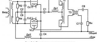
From the circuit diagram of the amplifier it is clear that between the anode of the pre-terminal stage L1 and the output push-pull stage L2, L3 there is no transition capacitor that would introduce a phase shift. This circumstance made it possible to apply very deep negative feedback without the danger of self-excitation of the amplifier. A large amount of negative feedback sharply reduces the coefficient of nonlinear distortion, which does not exceed 1% with an output power of about 6 W. The feedback voltage is removed from winding II of the output transformer and is supplied through resistance R8 to the cathode of lamp L1. The feedback circuit also does not contain reactive elements that would introduce a phase shift.
Due to the fact that the anode of lamp L1 is galvanically connected to the grid of lamp L2, the normal operation of lamps L2 and L3 is ensured by careful selection of their mode using resistances R3, R6 and R7 so that the voltage on the control grids of lamps L2 and L3 in relation to their cathodes is equal to -12 V. In this case, the final push-pull stage operates in class A mode. The voltage to the screen grid of lamp L1 is supplied from the common cathode resistance R7 of lamps L2 and L3. The amplifier consumes a current of about 100 mA. The LF voltage, amplified by lamp L1, is supplied to the grid of lamp L2. A low frequency voltage appears at the cathode of this lamp in the same phase as on its control grid.
If you ground the control grid of lamp L3, then a voltage will act between it and the cathode in antiphase with the voltage between the control grid and the cathode of lamp L2, which is what is required for normal operation of the push-pull cascade. It is impossible to directly ground the control grid of lamp L3, since this will disrupt the operating mode of lamps L2 and L3, so it is grounded at low frequency through capacitor C3.
The sound transformers were supplied by TVZ-1-6, with them on all driven frequency responses there is always a rise from 10 kHz. This is the result of the compensation function. The result of the cables is subtracted from the measurement result “amplifier + connecting cables”, which leads to this effect. You need to make yourself a good cable, then this won’t happen. As the anode voltage decreases, Kni increases slightly, and as the anode voltage decreases, it decreases.
Negative feedback circuit
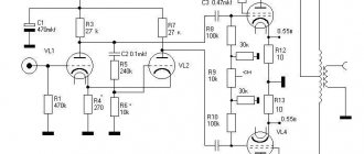
The amplifier is covered by general negative feedback (NFB) from the output to the input of the amplifier. This is the chain R4, R7 and R8. With the R7 trimmer you can adjust the depth of feedback over a wide range. As the OOS depth decreases, the gain of the entire circuit increases and nonlinear distortions increase. As the OOS depth increases, on the contrary, distortion decreases and the frequency response becomes more linear. However, many listeners note that as feedback increases, the amplifier sounds more “pinched.” This is all quite subjective. As they say, this is a matter of taste. You have a “handle”, steer as you like. Of course, this control has a very strong influence on the sound of the amplifier.
If, when you first turn on the amplifier, you hear a characteristic “howl” and “whistle,” then the amplifier is self-exciting. Turn off the amplifier and simply swap the wires from the secondary terminals of the output transformer.
power unit
If you have no experience building tube amplifiers, I do not recommend making this circuit. There are no constant voltage decouplings; all lamp modes are interconnected in a circular manner. It is somewhat difficult to set up. The circuit is a push-pull self-split with direct connection of cascades on EF22 and 6P3S-E.
I couldn’t resist - I finally attached the mirror lighting.
Measurements at 8 W output power. At 10 W, the THD increases to 1.2%.
Despite the clumsy spectrum, the sound is simply killer: lively, natural. You can touch the bass with your hands, it is so prominent and expressive. Here's a video I recorded:
6p1p - two-stroke LUMZCH with a simple transformer
The article discusses approaches to constructing a tube amplifier using low-power 6P1P beam tetrodes. 6P1P light bulbs are quite old, but they are very compact and have good characteristics. Initially, you can limit yourself to manufacturing an amplifier with a classic push-pull transformer of low power. For a device with single lamps, a transformer with a power of 25-30 VA is quite suitable. The appearance of the output beam tetrode, its connection diagram and ceramic sockets for wall-mounted mounting are shown in the picture.
When building a tube amplifier yourself, you should initially make reasonable decisions about its design. If you have experience and the ability to use printed circuit boards, then it is better to make printed circuit boards. If not, then do it with hanging installation. Surface mounting does not have any advantages over a well-designed printed circuit board. This is a tramp method of production, and the arguments in support of it contain only show-off to hide a lack of qualifications or laziness. The PKL-9 panels are ceramic and that’s great. They can also be used for printed circuit installation. In this case, it is better to remove the iron shell with a Dremel. The socket is soldered either directly on top of the board tracks, or part of the terminal tab is cut off lengthwise with a dremel, making it narrower. In this case, the socket can be inserted into the holes drilled in the board for desoldering.
At the very beginning of the presentation, I must say that the traditional, ingrained in people’s consciousness, approach to presenting an article from the name and choice of lamps is neither reasonable nor correct. It is unwise to start choosing a car with the engine and wheels, since first they evaluate the purpose, cost, aesthetics, functionality and other characteristics. Common sense suggests that the most important component of a tube amplifier is the output transformer. The quality of the entire amplifier depends on its quality. The cost of the output transformer can be 80% or more of the cost of the entire project. Everything depends on the choice of transformer, its manufacture or purchase, including the choice of the appropriate type of lamps. My presentation of the material in the traditional order has a different purpose. Selecting a suitable transformer will ensure good sound quality even in a simple push-pull amplifier. When choosing a scheme, you should remember that the lamps are finger lamps and you can limit the size of the resulting structure. As an output transformer, you can use power units of the TS series, as well as power units from Vega. You can also use other simple rod-based power devices from transistor units with suitable windings. It is better to limit the power of the used output transformer to 30-50W.
With a power of 10 W in each 6P1P anode, a stereo amplifier will need an 80-watt anode power transformer. You can use a pair of 36-watt power supplies. You should not bother too much with the windings, since not only a series connection is applicable, but circuits with doubling the voltage are also acceptable. In addition, you should take care of the power supply to the incandescent circuits. For small amplifiers, TN transformers with a small no-load current are applicable. But I don’t recommend using TAN transformers. The reason for this is experience, which has shown that these are transformers with a large no-load current, and therefore with a large dissipation. However, first the transformers should be measured in practice. If you can find a TAN with an idle current of 25 mA, then you are lucky.
Below are diagrams with differential connection of output transformers. We can assume that such circuits make it possible to build amplifiers of the next, higher class. For differential switching of output transformers, you will need to carefully select an output pair from a large batch. This is an expensive pleasure. But otherwise such a scheme cannot be defeated. And the differential switching circuit is worth implementing. And the sound quality and power will pleasantly please the creator. The pictures provide brief information on the characteristics of transformers.
Below is a similar circuit with other similar transformers in the same size. The difference lies in the change in the order of connecting the windings of the output transformers. By correctly switching the windings, the required transmission characteristics can be achieved.
With a large supply of 6P1P light bulbs, as well as with a supply of PLC-9, parallel switching of lamps in each arm can be used. The characteristics of the 6P1P tetrode are quite decent, the light bulb is quite stable. It will be quite possible, although labor-intensive, to select identical lamps from a full box. With time and patience, you can get a good 12-25 W amplifier without any problems. If you use the possibility of ultralinear switching, then the output transformer must have taps in the primary winding that relative to the center The number of turns and voltage of these taps for a 6P1P lamp, as a rule, is 25-30% of the number of turns of the winding of each arm.
When using laminated transformers, it is advisable to have thinner iron plates in the cores. But if you have crazy hands, standard transformers with split strip cores are also suitable. Even armored low-power transformers of the TN-XX-127/220-50 series can be honored and used in such amplifiers. It is mandatory to have separate primary windings of a 127 volt armored transformer.
If you use a self-balancing phase inverter circuit, then you will have to spend both halves of the triode. In this case, it is advisable to install another finger triode at the input, since when using feedback, one lamp at the input of the UMZCH may not be enough. If you use a split-load circuit as a phase inverter, then only one half of the triode is required. In this case, the first half can be used as a buffer link. Then the gain will be quite enough. Each bass reflex circuit has its own advantages and disadvantages. However, in the simplest case, you can get by with a minimum number of lamps. Another circuit with dual lamps. The transformer is 60 W in size; there is no need to load it with more than a couple of lamps in the arm.
There is no need to install additional drivers in front of each 6P1P tetrode; this lamp has good sensitivity. A standard circuit is suitable, with the signal supplied from the coupling capacitors directly to the tetrode grids. There can be no problems in the build-up of 6P1P. When doubling output lamps along grids and anodes, it is advisable to install equalizing resistors. 6P1P is quite a decent light bulb with good gain, rich sound and low heat generation. To describe the practical implementation of the scheme, I will take text from a magazine or brochure. Naturally, I’ll show you a link to the original source.
Evgeniy Bortnik, August 2015, Russia, Krasnoyarsk