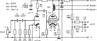
Tube output transformer
An industrial transformer of the OSM-0.1UZ type (iron ШЛ 2.5×84 cm, Qс=2.5x4-10cm²) was used as the output transformer. The layout of the windings on the frame is shown in Fig. 6. Transformer leads 1K and 6H are connected to the anodes of the lamps. The anode winding has 6 sections. Each section is wound in a row (turn to turn) and should fit into two layers.
When winding, you need to pay attention to the fact that the beginning of one section (for example, 1H) is on one edge, and the beginning of the next section (for example, 2H) is on the other edge of the frame. In this case, the sections are easier to connect. The number of turns in the section is 437, wire diameter is 0.27 mm. As a result, when connecting sections in series between the +Eo and Al, A2 terminals of transformer T (Figure 1), we obtain two half-windings of 1311 turns each.
The output winding has 5 sections of 85 turns of wire with a diameter of 0.35 mm. The beginnings of the sections are located on one edge of the frame (on the left in Fig. 6), and the ends on the other edge. Each section is wound in a row in one layer. If radio amateurs want to get a different output impedance of the amplifier, then it is necessary to change the number of turns of the output winding of the output transformer.
For example, for Figure 1 (4 output tubes, fixed bias), the nominal output impedance is 4 ohms. Therefore, to obtain the required output resistance of the amplifier (Zout), it is necessary to multiply the number of turns of the section (with a resistance greater than 4 Ohms) or divide (with a lower resistance) by √Zout/4 Ohms times. This means that in order to obtain an output resistance of 8 Ohms for Fig. 1, it is necessary to multiply the number of turns of the section by √8/4. As a result, we get 85√2=120 turns. The wire cross-section for the output winding must be selected from Table 1.4.
S8Ohm=S4Ohm/√2=0.057cm²/1.41=0.04cm²
For an output resistance of 8 Ohms, we find in Table 1.4, based on a cross-sectional area of 004 cm², a wire diameter of 0.23 mm. I draw the attention of radio amateurs to the fact that a simple DIY tube amplifier, unlike a transistor amplifier, has the peculiarity that it produces maximum power at a certain (nominal) load resistance. When the load resistance is greater or less than the rated one, the power drops.
Design and details of a tube amplifier
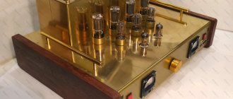
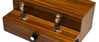
To make an amplifier, depending on the size of the transformers, the number of tubes and capacitors, a U-shaped chassis is made (but old tube radios once made these). The material can be aluminum, duralumin or galvanized sheet.
It is advisable to place the output lamps above holes with a diameter larger than the lamp itself, so that air from the chassis basement can freely rise up around the lamp. It is unacceptable to use the chassis as a common wire. The latter is made with tinned copper wire with a diameter of 0.9-1.0 mm, grounded at one point near the power supply, then stretched from the bottom side of the chassis parallel to the top cover and attached to the chassis using insulating material.
1- output stage lamps 2.3- power transformers 4- output transformers 5- preliminary stage lamps 6- electric capacitors
From the grounding point, a common wire leads to the output stage lamps, to the output transformer, and then to the preliminary stage lamps and to the input socket. The desired placement of power (power) and output transformers is shown in Fig. 7 (top view). Power transformers (transformer) are selected according to the above technical data and from the table data.
The circuit shown in Fig. 1 requires one TS-250 power transformer, two TS-180, or two TS-100 would be a stretch. If you are content with a power of 26 W per channel and eight output lamps, then one TS-180 transformer will be suitable for power supply.
Before winding a transformer (for example, TS-180), it should be connected to the electrical network and measure the voltage on the secondary windings, so that later, after unwinding one of them, count the number of turns in it and, dividing them by the voltage in it, calculate the number of turns per volt ( the number is constant for a given transformer).
The number of turns in the remaining windings is obtained by taking the winding voltage from the table and multiplying it by the number of turns per volt. The diameter of the winding wire is determined by the current from the table in our article and table. 1.4
Before unwinding transformers of the TC series, you must first disassemble the fastening clamps, then, holding one end of the iron core in a vice through cardboard spacers, sharply hit with a hammer a piece of plywood or wood attached to the other (not clamped) end of the core.
Thus, the core will split into two parts. Then you need to unwind the windings placed on two frames, leaving the screen and network. If there is no screen winding, then it must be wound in one layer turn to turn. One end of this winding should be cut off without leading out and insulated.
The insulation of the windings between the layers can be done with a layer of chart paper (rolled) or other. The insulation between the windings (sections) in output transformers consists of three layers on the bottom and top of a layer of paper, and between them a layer of varnished cloth. The insulation can be “dry”, i.e. do not soak if the homemade amplifier will be operated in dry rooms without sudden changes in temperature.
If operation is expected in cold, damp rooms, then the frames with transformer windings are boiled in paraffin. Please note that the insulation between the mains winding and the screen winding, as well as between the screen winding and the step-up winding, must be reliable, because the screen winding is connected to the common wire (ground).
Parts used in a tube amplifier:
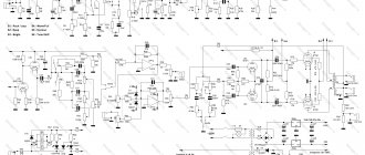
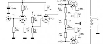
According to Fig. 1: R11, R13, R19, R20 10-15 kOhm, 0.25-1 W; R12, R14, R21, R22 390-470 kOhm, 0.25-1 W; Rl7, R18, R25, R26 510 Ohm-1 kOhm, 2W; R15, R16, R23, R24 10-51 Ohm, 2W. Any type of resistors: C2, C4 K50-12, K50-7, K50-27 (can be 100 μF); S1 – KM-5, KM-6; SZ - K73-17 at 400V and S5, S7, S7 - K73-17 at 250V (from modern color TVs).
According to Fig. 3: S1-S3 – toggle switches P2T-7, P2T-21, P2T-3; V1, V4 – KTs402A, KTs404A, KTs405A, KD209B (4 pcs); V3, V6 – KTs405G or 4 diodes with a reverse voltage of at least 200V; R1, R2, R6, R7 – C5-37-6 (power filter for color TVs of the 3USKT, 4USKT series); C1, C2, C6, C7 – K50-7, K50-27; SZ, C4, C8, C9 - can be any and have a larger capacity, for a voltage of at least 100V.
Specifications
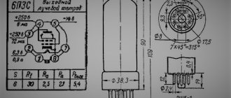
The 6P3S radio tube, as a representative of devices used in ULF, is distinguished by its high output power, good slope characteristics, low nonlinear distortion coefficient and pass-through capacitance. Thanks to its parameters, it is successfully used in output stages of low-frequency amplification and even by modern standards shows good results.
Main operational characteristics of 6P3S:
- voltage: filament – up to 6.3 V, anode – up to 250 V;
- screen grid voltage – up to 250 V;
- current: anode – up to 72 (± 14) mA; filament – up to 900 (± 60) mA;
- output power – 5.4 W;
- gain – 13.5;
- characteristic slope – 6 (± 0.8) mA/V;
- internal resistance – up to 22.5 kOhm;
- capacitance: input – 11 pKF; output - 8.5 pKF.
Setting up a tube amplifier
With a circuit with a fixed bias, the setting comes down to: 1) Selecting such a voltage using R3, R8 (Fig. 3) and R29 (Fig. 1) so that the power dissipation at the anode of the output lamp does not exceed 15 W, i.e. so that the anode current (through R15, R16, R23, R24) does not exceed 15W/400V-37.5mA. Accordingly, the voltage at the cathodes of the lamps (the leg in the absence of an input signal should not exceed 51 Ohm × 0.0375 A = 1.91 V.
Lamp currents may differ slightly, so lamps in the arms must be selected with approximately the same currents. In addition, to prevent magnetization of the output transformer, it is necessary that the sum of the lamp currents of one arm (VL3, V14) is equal to the sum of the currents of the other arm (VL5, VL6).
Before test switching on, it is necessary to load the channel outputs with resistors of the PE-50 type, equal to the rated output impedance of the amplifier, or with powerful loudspeakers. Turn on toggle switch S1 and warm up the lamps. After approximately 45-60 seconds. turn on the toggle switch for the anode power supply of one of the channels (for example, S2) and immediately turn it off.
If, when turning on S2, the output transformer “hums” strongly or the loudspeaker hums if it is connected instead of a resistor, then it is necessary to turn off S1 and resolder the ends of the output transformer: remove the one that was “sitting” on ground and solder another one in its place, to to which feedback is connected. This completes the setup.
Analogs
Modern industry does not produce complete analogues of 6P3S. However, it can be replaced with identical or similar parameters: 6P13S, 6P15P, 6P14P, or imported lamps: 6L6GB, 6CN5, 6L50V, EL35, 1540, EL39, 5932, 6L6G, 7581A, 5881. Many of them have long been discontinued, but are still sold in large radio stores.
In Soviet times, they also produced 6P3S-E, which was distinguished by higher reliability and longer service life - 5000 hours, instead of 500 for the usual 6P3S. At the same time, a more powerful generator electron tube G807, similar to the one under consideration in parameters, but differing in pinout, was produced.
Radio tube 6P3S
A 6CCD radio tube is a beam tetrode. which is designed to amplify low frequency power signals. The 6P3S tetrode is used in output (single-cycle, push-pull) stages of radio receivers and low-frequency amplifiers (ULF), as well as as a high-frequency generator in tape recorders, radio transmitters and other equipment.
Rice. 2. Appearance and dimensions of the 6P3S lamp.
Rice. 3. Pinout and pinout arrangement in the 6P3S lamp.
Radio lamp 6Zh3P
The 6Zh3P radio tube is a tetrode designed for broadband amplification of high frequency (HF) voltage. The 6Zh3P lamp is used in intermediate frequency (IF) amplifiers of audio and image signal paths of television receivers without automatic gain control (AGC).
Rice. 4. Appearance and pinout of the 6Zh3P radio tube.
Original source: unknown.
ULF assembly
Now assembly. One side panel from an old computer case was used for the chassis, and the second one was used for the bottom. According to the intended design, the lamp panels should be raised above the chassis, so rectangular holes were cut out in the latter, which I covered with foil fiberglass boards with lamp panels soldered into them.
There was also this remark in the original source.
Therefore, it was necessary to come up with an anode voltage delay. I didn’t want to put the toggle switch on the anode, because I don’t like sharp transient processes in the form of surges in the anode and grid currents. Taking into account the above (and shown), the power supply and softstart circuit turned out like this.
Barrel organ hooligan
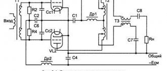
Perhaps the most famous product based on 6P3S is the so-called “organ organ”. This is the unofficial name of a hooligan transmitter that can be made at home to operate in the upper frequency range (above 1500 kHz). It was especially popular among novice radio amateurs in the period 60x-80x. For radio broadcasting, in those days, it was connected as an attachment to the output of a tube ultrasonic sounder, from which power and an amplitude-modulated signal were supplied to the anode of the lamp.
The circuit of a 6P3S-based barrel organ is quite simple and does not contain a large number of radio components. Some solutions can be downloaded from the links
,
,
. Instead of 6P3S, you can take any of the domestic analogues, like 6P13S, 6P15P, 6P14P.