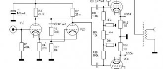
↑ Scheme of a tube amplifier by S. Sergeev
High power and the presence of suitable tubes in the driver stage persuaded me to build my first push-pull.
The amplifier sounds very good and has the following parameters: Supply voltage 360 Volts Power consumption from the network 170 W Sensitivity 0.7 Volt Output power 40 W
Armed with a list of parts, I went to the market. Unfortunately, this is the only place where you can buy radio parts in my city.
Tube amplifier: advantages and disadvantages
What are the positive aspects of choosing an integrated amplifier or preamplifier using tubes compared to models that operate on the basis of transistor signal amplification?
The most significant advantages of choosing lamps include the following points:
- Relative simplicity of design. The circuitry of such devices is much simpler than that of transistor-type models. All this affects the possibility and cost of equipment repair;
- Unique sound due to a number of features and effects. Among these are a significant dynamic range, a high smoothness of the transition to amplitude limitation, a very pleasant overdrive and others;
- Significant lamp life (from 10,000 hours) of the device;
- High reliability and resistance of the device to short circuits under load;
- Non-criticality of equipment to temperature overloads;
- Absence of “white noise” (hissing), characteristic of semiconductor equipment models;
- Stylish appearance that can successfully and harmoniously complement a wide range of interior styles.
Of course, a tube power amplifier is not the epitome of all advantages. Otherwise, representatives of this technology would completely supplant transistor devices for similar purposes. The weaknesses of the device include:
- Considerable weight and dimensions of the device due to the fact that the dimensions of the lamps are much larger than the transistors;
- Greater noise level during operation of the device;
- The need for time to preheat the tubes before reaching the optimal operating mode of the amplifier;
- High output impedance. This factor somewhat limits the range of speaker systems with which specific single-cycle or push-pull tube amplifiers are compatible;
- Less linearity compared to semiconductor devices;
- High heat generation and power consumption;
- Low efficiency (within 10%);
- Susceptibility of an amplifier using HF, UHF and microwave lamps to interference.
Without a doubt, based on the number of weaknesses inherent in tube preamps, they cannot be called ideal. But the unique color of the sound that is obtained when using them compensates for all the listed shortcomings.
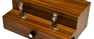
↑ Power transformer TSA-270
As a supply transformer, I wanted to use an unwinded standard transformer, for example TS-180. Only TCA-270 was found for me, which I bought and went home, quite satisfied. Although the winding is aluminum (index A), it provides the passport parameters.
I connected TCA-270 like this:
Pins 7-17
are used to obtain the bias voltage of one channel
Conclusions 4-14
for anode power supply of one channel.
Conclusions 11-(21-12)-22
for 6P36S filament of one channel.
Conclusions 20-(10-10')-20'
for 6N1P filament of both channels. The windings I have given provide exactly the required voltage and current.
1.5. The last push
The post-war development of electronic tubes throughout the world was determined by the needs of developing ultrashort wave bands, brought to life by the development of radar, television, communications and broadcasting at frequencies of tens and hundreds of megahertz. It was with these exciting activities that the beginning of the production of lamps known as “finger” lamps (with heptal and noval sockets) was connected. "Flat stem" designs have now become common for lamps of all sizes. Frame grids and other innovations were mastered.
To be fair, it should be noted that prototypes of such lamps were also created in Germany - for Wehrmacht communications equipment.
In the 60-70s, many types of new generation lamps were created, with fantastic parameters by previous standards and ultra-economical cathodes - especially for operation in high-frequency ranges, in broadband amplification stages and in pulsed mode.
Many people are familiar with subminiature lamps with flexible leads. They were mainly used in rocket and aircraft on-board equipment (direct-heat models were used in portable communications equipment).
The latest breakthrough in radio tube technology can be considered the production of “nuvistors” - tubes created as a competitor to semiconductors, superior to the latter in terms of resistance to irradiation by a neutron flux. I think no comments are needed in this regard.
↑ Board for surface mounting
I would like to draw your attention to my non-standard way of creating boards. The fact is that I don’t etch the signet, I cut the foil on the PCB into squares measuring 2 cm x 1 cm and come up with a diagram for wiring the parts. For example:
The diagram according to which I soldered the parts onto the board.
The lines between the squares are jumpers. There are also longer connections, they are drawn as lines. The arrows on the squares indicate the place to which the wires from the lamp panels, or power, etc. will be soldered. For example, 3L1 means that the 3rd pin of the first lamp (6N1P) is soldered there, 8L2 means that the 8th pin of the 2nd lamp (6P36S) is soldered there. Those. the first digit is the pin number, the letter just separates, and the second digit is the lamp number. I'm not suggesting you do the same, it's just that this method is simple and saves time and money. It turns out to be a “canopy” on PCB.
Here's the board I got
1.3. Spider caps
In the mid-30s, European lamps of a new generation appeared - the “red series”. For the first time, the idea of “harmonic” series began to be put into practice: sets of mutually consistent (as it was believed) types of lamps were developed - in a targeted manner for the construction of certain classes of mass-produced radio receivers.
These were lamps with an unusual, so-called. pinless base (with side slats). Such plinths were also called “spiders”. However, they were also produced with an American “octal” base and with other bases.
Features of the new stage were an extremely wide range of lamps, as well as the appearance of combined lamps. For example: ACH1 is a hexode with a triode. Electrical parameters by this time had increased significantly.
Captured radios with “red series” lamps were once imported in considerable quantities from Germany. Lamps for them were in great demand, but now they are quite rare.
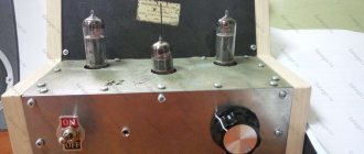
↑ First launch
The first launch was successful. There is only one pity: at that time I did not have a multimeter at hand. The old one is broken, I haven't bought a new one yet. In general, I set it up using a barbaric method: I adjusted the offset so that it was minimal, but the anodes did not turn red. Everything seems to be working, it’s time to hide it in the case. And then I was very lucky: an acquaintance of my father gave me an old non-working guitar ULF “Minor”, which was immediately gutted.
The case from “Minor” fit perfectly, two TS180 output transformers (lying) and 2 boards of the ULF itself fit into it, but the TCA-270 power transformer did not fit. Therefore, a separate case was made for the power supply from chipboard and plywood. The top of the body is covered with self-adhesive tape.
Holes for the panels were drilled. Everything is installed, and now the long-awaited launch in the case. I turn it on and... I almost went deaf from the whistle as the lamps warmed up! Cursing, I turn off the power and go to the market to buy a shielded wire, buying it with a reserve.
Signal to noise ratio
The next parameter is the signal-to-noise ratio; in modern tube amplifiers it most often corresponds to 90 dB or more. In general, this value can be considered very common when comparing the characteristics of various devices, even if presented in different segments. Therefore, if the task is to choose a good single-ended tube amplifier or, for example, a push-pull amplifier, then the parameter under consideration will not always objectively reflect the competitiveness of a particular device. One way or another, the higher the corresponding indicator, the better. It is desirable that it be at least 70. Some top amplifier models provide a signal to noise ratio of more than 100 dB. But their price, as in the case of harmonic distortion, can be impressive.
↑ Fighting arousal - shielding
To eliminate self-excitation, which manifests itself as a whistle, it was necessary to shield the grid circuits of the 6N1P triode and the wires in the grid circuits of two 6P36S.
The 6P36S anodes were not shielded. The whistling stopped. I start it up again and hear: one channel works great, but in the other there are clicks instead of bass, plus a sluggish and hoarse midrange. Of course I was upset at this point. And I tried everything, but the reason turned out to be incorrect mesh screening
. The screens were not grounded correctly.
I redid it, grounded the ends of the screens with a star - this is when all the wires go to one point and to the body. The interference and excitement disappeared, the clicks in the bass stopped, the bass became clear, elastic, and both channels began to sing equally beautifully.
Since the 6P36S lamp is prone to self-excitation, if the shielding is poor, a whistle may appear, which indicates a parasitic connection between the input and output of the amplifier. You should try to make the wires as short as possible; the wires carrying the signal should be shielded. In case of self-excitation, which manifests itself as intermittent low-pitched sounds and clicks, it may also be necessary to install anti-excitation resistors in 6P36S grids with a resistance of 0.5-1 kOhm.
Capacitors
In a tube amplifier setup, you should use different types of capacitors for the system itself and the power supply. They are usually used to adjust the tone. If you want to get high-quality and natural sound, you should use a coupling capacitor. In this case, a small leakage current appears, which allows you to change the operating point of the lamp.
This type of capacitor is connected to the anode circuit, through which a large voltage flows. In this case, it is necessary to connect a capacitor that maintains a voltage greater than 350 volts. If you want to use quality parts, you need to use parts from Jensen. They differ from analogues in that their price exceeds 3,000 rubles, and the price of the highest quality radio elements reaches 10,000 rubles. If you use domestic elements, it is better to choose between the K73-16 and K40U-9 models.
↑ Setting and feature of fixed offset
After purchasing the multimeter, the setup became easy, the device is in working order and at hand: resistor R9 set the same voltage on the cathodes of the lamps, and the bias resistor set the voltage to 0.55 Volts.
However, there is one unpleasant feature of a fixed offset. When the network voltage changes, the lamp mode changes. Once the voltage in the network rose to 250 V and one 6P36S went out of mode, the anode became hot, the quiescent current increased to 80 mA (with the prescribed 55 mA)! Fortunately, I noticed this immediately and turned off the ULF. I had to install a voltage stabilizer "Ukraine-3", mine produces 215 V. Due to insufficient voltage on the primary (and, accordingly, on the secondary), the voltages on the anodes dropped from the required 330 V to 313 V. I raised the quiescent current to 64 mA ( drop across resistors R12, R13 = 0.64 V).
Other parameters
The remaining parameters - support for certain communication standards, power consumption - are significant, but secondary
It makes sense to pay attention to them, all other things being equal, according to the indicators that we discussed above. One way or another, for a modern amplifier, it can be considered typical to have support for a sufficient number of stereo pairs - about 4, audio output for recording sound
Regarding power consumption, the optimal figure is about 280 W.
Of course, when considering the question of which tube amplifier is better, many subjective factors also play a role. Most often, music lovers evaluate the corresponding devices based on their design, build quality, sound level, and ergonomics.
All of the above parameters can be compared with the price of the device, which can be presented in a very wide range of values. But a person for whom the question of why a tube amplifier is better than a transistor one is not particularly relevant, since he knows the answer to it, the price, as we noted above, cannot always be considered as the most significant criterion when choosing a device for listening to his favorite tunes.
↑ Total
After tuning, the amplifier was painted matte black to restore the shabby exterior.
I was pleasantly surprised by the sound of this amplifier. I only listen to rock, so when comparing I only included that. The signal source is a computer with a Sound Blaster Audigy sound card, and the output is a 3-way AIWA SXNH3 speaker. The amplifier sounds very beautiful: ringing, clear midrange; not clicking, distinct high frequencies; awesome soft elastic bass. I compared it with SE on 6F5P and SE on 6P14P. I undoubtedly like my two-stroke 6P36S better.
What is it needed for?
The preamplifier is responsible for preparing the signal coming from a microphone or other source for the necessary amplification. It is capable of boosting the low signal as well as cleaning it up. This improves the quality of the incoming sound. In addition, a preamplifier can be used to adjust the signal or mix several sounds into 1. This device is used to adjust the sound to the initially specified power level. It is located as close as possible to the signal source (for example, a microphone, radio tuner, player). This feature ensures that the resulting sound is converted and transmitted without changes to the power amplifier.
Regardless of the level of design complexity and output impedance, the task of any preamplifier is to transmit a high-quality signal. There are many preamplifier circuits.
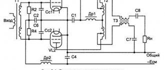
Push-pull triode stage
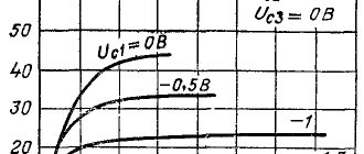
In Fig. Figure 1 shows a diagram of a push-pull cascade using 5881 beam tetrodes in a triode connection with a fixed bias on the grids. The family of characteristics of a pair of lamps in this mode is shown in Fig. 2. The load lines are given for an anode supply voltage of +400 V and a bias voltage of -45 V. The dotted line shows the individual characteristics of each lamp, and the solid lines connecting the dotted curves show the joint characteristics of both lamps in the cascade. The thick solid line in the center is the load line for the load resistance between the anodes of 4 kOhm. Under these conditions, the cascade delivers 13.3 W to the load at 4.4% distortion (4% at the 3rd harmonic, 1.5% at the fifth).
In this case, the 4 kOhm load line is an idealization. It corresponds to the laboratory conditions under which the measurements were made. Unfortunately, the actual operating conditions of the amplifier are usually far from ideal. The load resistance of the lamps can differ from 4 kOhm in any direction and, what is most unpleasant, contains a reactive component.
Rice. Figure 3 shows the dependences of the amplifier parameters with load variations. One pair of curves shows the dependence of the maximum stage power and distortion at maximum power for changing the load resistance from 1.2 to 12 kOhm. These limits in Fig. 2 are marked with thick dotted lines. The real load of the amplifier, a loudspeaker (without crossover filters or with them), has, in addition to the active one, also a reactive component, which transforms the load straight line into an ellipse (Fig. 4).
The second pair of curves in Fig. Figure 3 shows how maximum power and distortion vary with a hypothetical load containing a 4k ohm resistive + reactance connected in parallel and reducing impedance
up to 1.2 kOhm and connected in series to increase it to 12 kOhm. If we compare these curves with the corresponding ones for the pentode cascade (Fig. 8), then the advantages of the triode immediately become clear.
Classic two-stroke
To assemble an amplifier with an output power of about 20 W, you can use the proposed circuit. The output stage is made on 6P43P.
The TS180-2 from a tube TV is suitable as a power transformer. Transformers for the output are suitable as TN.
As the basis of the device, you can use a sheet of duralumin measuring 200*160 and 4 mm thick.
Almost all parts of the amplifier are attached to it, and the installation itself is carried out using a hinged method. The frame of the product can be painted white, which looks more attractive, as opposed to the usual black. At the corners of the plate, stands made of polished duralumin are attached, which serve as legs.
Power and output transformers are covered with tin screens to reduce interference
To save space, the power supply choke can be removed by soldering a regular P-filter. It can be assembled using two 300 μF capacitors and a 100 Ohm 15 W resistor.
For headphones
This amplifier can be recommended for beginners due to its simplicity of design.
The assembly will be carried out according to a circuit with a transformerless output on 6N6P.
For the amplifier in question, you should use high-impedance headphones with a resistance of 600 ohms for each speaker.
To eliminate the ripple of the anode voltage, a 5 H inductor is used in the circuit. It is advisable to use metal to create the chassis.
When assembling the amplifier, the power transformer should be placed on top to avoid interference with the output circuits.
The circuit is mounted using a hinged method, which will minimize the number of wires.
A thick copper wire should be used as a negative bus.
The filament wires can be connected in parallel so as not to be connected to each socket separately.
If desired, the circuit can be supplemented with a signal level indicator.
After assembly, the amplifier needs to be configured. The procedure boils down to adjusting the trimming resistors along the cathode, ensuring a minimum nonlinear distortion factor. The signal can be monitored using a spectrum analyzer.
Input selector
I organized an input selector on three TAKAMISAWA relays (according to the number of inputs), which switch a low-current signal. I didn’t make a printed circuit board for the switch; I assembled everything on a breadboard.
The diagram is something like this:
For the sake of beauty, I installed dial indicators. The indicators are controlled by the domestic K157DA1 microcircuit. The circuit has been converted to single-pole power supply, a printed circuit board is included.
The switch, K157DA1 microcircuit and indicator backlight diodes are powered from a single stabilized voltage source.