High quality DAC AH-D6.1 on AK4493/AK4490, premium version of AH-D6
2 years have already passed since the release of the AH-D6, the DAC turned out to be very successful, and with its modest budget, the DAC received a good response from radio amateurs who repeated the design. Seeing how top-end components are put into a budget board, I decided to develop a new, four-layer board and make some improvements to the basic design of the AH-D6.
In addition to the transition to a four-layer board design, the following design changes were made:
- The output op-amp in the subtractor link was buffered by the electronics, which made it possible to use many op-amps without a significant increase in distortion for loads of 1 kOhm and higher, which also reduced the impact on the final sound of various cable products.
- A primary passive filtering section was added to the analog filter.
- The filter now uses resistors of size 1206 (however, no one forbids soldering 0805 into existing seats), so in top-end assemblies you can consider using melf-resistors 0204 metric, which exactly correspond to size 1206. In addition, I note, even ordinary thick-film resistors of size 1206 are less noisy than their smaller counterparts, so even in a budget version, installing 1206 resistors gives a small advantage.
- The power supply circuit for the AK449x reference voltage circuits has been optimized and improved.
- Additional op-amp correction circuits have been added to the ION-FSh-OU stabilizers, which has made it possible with most used op-amps to avoid parasitic generation and ringing when the decoupling resistor between the stabilizer output and the output capacitance is abandoned.
- With the transition to a 4-layer design, the board routing has been significantly optimized.
- It was decided to use the space for power stabilizers for the digital part more optimally. So, in relation to the AK4493, it was decided to abandon the use of the built-in LDO, so a separate stabilizer was allocated on the board to power the chip core (DVDD-1.8V). The power supply of the microcontroller and TVDD was combined.
- The used element base was optimized, and a more successful combination of op-amps for the analog filter was selected.
Attention! Since the power supply of the microcontroller and ak4490/ak4493 has become common, then in the case of flashing an already assembled board, make sure that your programmer is configured to supply 3.3V to the Atmega88 (it’s even better not to supply power from it to the board at all, removing the supply voltage selection jumper). Applying 5V to the DAC board can lead to complete failure of the DAC chip!!!
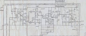
Scheme
The device allows the use of the younger AK4490EQ chip in place of the AK4493EQ, in this case the entire DVDD+1V8 power line from U21 is not unsoldered (see power supply diagram for the digital part) and it is recommended to reduce the ratings of R15 and R17 to 1 kOhm, which will increase the VDDL/R power supply to 5, 5V (the manufacturer allows a safe increase in voltage up to 7.2V). This difference of 0.5-0.6V between Vref and VDDL/R is optimal for the AK4490EQ, as it allows for additional distortion reduction.
Unfortunately for ak4493, such a trick is not possible and you have to be content with a difference of within 0.25V.
Power supply circuit for the digital part
Analog filter circuit
For the new DAC, taking into account the use of Vishay melf resistors (size 0204), a new version of the analog filter was calculated.
In the low-pass filter section, it is recommended to use op-amps: OPA1656, OPA2156, with deterioration: OPA2810, OPA1642, OPA2141, OPA2140. In the difference processing link: OPA192, OPA828, with deterioration OP42, OP1611, OPA827, OPA1641, AD744 and with a big reservation OPA189. The choice was made from more than 10 different op amps, both based on objective measurements and the results of repeated listening. OPA192 was frankly surprised by the actual measurements (with ED distortion indicators at the opa828 level) and sound quality, which made us turn a blind eye to the datasheet.
As for the OPA189, the new (purchased in 2022) copies showed a noticeable change in the direction of increasing THD with increasing frequency (but not critical, up to 0.0004% at a frequency of 15 kHz with an ED) than my first copies 0.00026%, purchased at the dawn of their release in the official TI store. Which allows us to assume the presence of a fake (which is unlikely, the appearance is without suspicion, bought at Terraelectronics) or, more likely, an update of the crystal - a change in the internal correction values. For OPA192 I cannot rule out a similar story, but what I have on hand measures up perfectly, see measurements below.
AD8065 cannot be used in this circuit due to the high probability of oscillation; one of the two copies tried to break into oscillation, while the second worked stably and showed quite good measurement results in D6.1 at the level of 0.00021% for 15 kHz (in D6 their use acceptable, but with good power supply blocking capacities).
A couple more possible filters, with common ratings:
Low-pass filter 5.9k -> 6.8k and 2.61k -> 2k capacity 1n -> 680p and 390pf -> 330pf, in the difference processing section 2.7k and 330pf.
Low-pass filter 5.9k -> 4.7k and 2.61k -> 1k, capacitances 1n -> 1.5n and 390pf -> 470p, in the difference processing section 2.7k and 330pf.
Printed circuit board
The AH-D6.1 DAC is made entirely in the dimensions of the AH-D6 on a four-layer printed circuit board measuring 100x69mm.
Distortion measurements of top version AH-D6.1 on AK4493
The measurements were made using a new ADC, whose intrinsic distortion is ~0.00003% at an input signal level of 0.6V RMS. The necessary coordination of levels was carried out by a set of dividers and a scale shift. Please ignore network interference < 1 kHz for now, these are flaws in the measuring stand. In the filter of the sample being measured, OPA1656 and OPA192 were installed (for OPA828 the measurements are almost identical, the rest are measured worse).
Below are measurements for the full scale of the DAC, 0DB - which corresponds to the AK4493 - 2.5V amplitude voltage at the filter output, with a load of 2kOhm, for different frequencies: 1kHz, 5kHz, 10kHz, 15kHz.
Signal spectrum 1kHz, 0dB
Signal spectrum 5 kHz, 0 dB
Signal spectrum 10 kHz, 0 dB
Signal spectrum 15 kHz, 0 dB
Distortion measurements of AH-D6.1 version on AK4490
As an example, I give measurements of a simpler version of the DAC with the AK4490 chip.
Signal spectrum 1.08 kHz, 0 dB
Signal spectrum 1.08 kHz, -3 dB
Signal spectrum 1.08 kHz, -7 dB
Firmware and configuration
Fully consistent with that of the AH-D6
DAC sound
As you can see, the DAC distortion is at a low level, even at 15 kHz its level remains very low. This ensures high transparency and overall sound comfort.
Subjectively, to my ears, the DAC turned out to be very musical (I expected less from an analog filter on an op-amp); the sound level is noticeably superior not only to Chinese crafts, but also to many popular amateur designs that I had a chance to listen to. With proper assembly and use of original components, the DAC can adequately compete with much more expensive DACs from other authors.
Addition
To test the new version of the DAC, a two-layer version of the AH-D6.1 board was also made. There are no plans to publish the 2-layer board project to the general public, so as not to occupy the lower-end budget of the AH-D6. Many developments and recommendations are already quite applicable to the AH-D6.
The engineering version of the board does not have additional load resistors R99 and R100; the use of these resistors allows you to bring the stabilizer transistors to the linear part of the characteristic and obtain the most even output resistance of the latter. Since there is plenty of space for containers, resistors can be installed in their positions.
Also, R101 was subsequently added to the 4-layer, which solves the problem of generating some particularly crooked LP5907 instances in the event of no load. That is a rare case when galvanic isolation is not used, but the stub is still soldered to the board.
There is also no capacitance C114 (added just in case to avoid possible LP5907 generation, although I have almost never encountered this myself.
Reviews, discussion of issues on launching and debugging the AH-D6.1 DAC
Link to order 4-layer PCB in China from PCBWay
AK4490 DAC and its Chinese implementations
Chinese manufacturers are very actively responding to the release of new DAC models, and following well-known brands, they are introducing their products at a significantly lower price. I listened to a number of Chinese DACs, but I’ll tell you about their sound and what they cost in another article. Having taken an eminent and rather expensive American DAC, which was positioned by sites audiomania.ru and so on as Hi-End class sound, for an audition from a friend who loves high-quality audio, I was extremely dissatisfied and disappointed with the sound. And of course, at this moment, Chinese tempting manufacturers came up with their own options.
You shouldn’t expect anything supernatural from the sound of Chinese DACs, but listening to American DACs seemed to tell me that things couldn’t get any worse. I was also intrigued by the technical capabilities of the latest AK4490 DAC from Asahi Kasei Microdevices. Why Asahi Kasei?
I am familiar with the sound of the EGO-SYS [email protected] , which has been installed in my computer for several years and is built on a DAC from Asahi Kasei Microdevices. Despite all the budget implementation, poor detail and channel separation, in budget solutions the DAC from Asahi Kasei sounded more natural and inspired than the “metalized” PCM1798.
And this was on an old DAC, and the AK4490 is positioned according to the datasheet no less, no more, as (quote): “A new generation 32-bit 2-channel Premium DAC. The latest technology and industry leader achievements are used to achieve minimal distortion and maximum dynamic range. The DAC has a new capacitive filter “OSR Doubler” built in, which has better parameters. In addition, the DAC contains 5 more different 32-bit digital filters.” Before I talk about the choice of a specific implementation of this DAC by Chinese manufacturers, I will focus on its characteristics. In addition to the already mentioned 32-bit capability, I was pleased that the AK4490 DAC supports frequencies up to 768,000 hertz for the PCM stream. For DSD, 11.2 million hertz is supported. Reread the sentence above again. In addition, 256-fold oversampling is used. Digital filters use 8x oversampling (352.8 kHz). Low jitter, low distortion, 255-position digital volume control.
Mono mode. Possibility of using external digital filters. If it is not clear why a digital filter is needed at all, it is the one that draws a smooth envelope from the steps that recreates the analog sound. There is a built-in clock (clock). I liked the declared data; you can only find out how it will actually sound by listening to the DAC. Therefore, I looked at different options for implementing this DAC/DAC in a Chinese online store. Unfortunately, no implementation uses all the capabilities of the DAC. for example, of the filters everywhere, only “OSR Doubler” is included (as translated by Google, which has a “wet and gentle timbre”), but the buttons or the ability to use other filters through the driver are not implemented, which is quite annoying. Globally, I saw that China has the most offers for two product variants. The first option is a soldered board, to which you need to additionally connect a transformer with variable voltage,
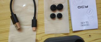
and the second option is a ready-made DAC in a miniature case, which has a connector for connecting a DC power supply (such as a telephone charger).
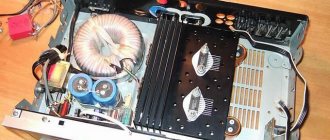
The cost is approximately the same - about 4000 rubles. The assumption that the DAC for the same money in the form of a board would be implemented better upon careful examination of the circuit was not justified. It turned out that the implementation in the form of a board only contains a power rectifier - large capacitors and a diode bridge, which eats up most of the space. The remaining PCB houses the DAC itself and the AD827 operational amplifier. Those. One cannot expect miracles from such a spartan DAC implementation. The SU0 XMOS U8 AK4490 DAC turned out to be much more interesting. Although it was initially intended that budget power in the form of a telephone charger be connected to it, the implementation of the DAC itself is much more interesting. First of all, USB support is implemented through the XMOS chip, which itself is a fairly powerful computing processor with a frequency of 500 MHz. The board also has two high-quality clock generators. One generator serves frequencies 44.1/88.2/176.4/352.8 kHz. The second frequency generator is 48/96/192. Those. Initially, a more thoughtful approach to achieving high-quality sound is visible. Good capacitors installed.
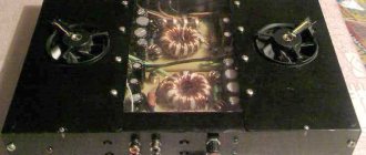
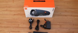
The NE5532 operational amplifier is inserted into the “crib” and can be easily replaced with any compatible one at will. And all this is housed in a neat aluminum case. The downside is obvious - food. But in this case, compared to board options with a rectifier already on the board, nothing prevents you from organizing proper power supply yourself. For this option, I implemented a simple current rectification circuit with stabilization. As a power source, I used a Chinese R-Core transformer producing voltages of 9 and 15 volts. In fact, without a load, measurements showed that the voltage coming from it was more than 10 volts. I decided to stabilize the power supply at 9 volts.
For this purpose, a foreign-made 7809 microcircuit was purchased, which is a 9-volt power supply stabilizer and can withstand current up to 1 ampere.
To rectify the current, I took Schottky diodes, which are known to have a very high speed compared to conventional diodes. The current from the transformer entered the diode bridge from Schottky diodes and then, already rectified, went into the capacitor - I installed the one that was available - an electrolytic one at 6800 mF 25 volts, shunted by a non-polar capacitor at 330 mF. Next, the current rectified from the 9 volt tap, which after rectification became 9 * 1.4142 = ~ 13 volts, went to the 7809 stabilizer and from it, stabilized at 9 volts, went into another smoothing capacitor at 2000 mF 25 volts, in order to be as “smooth” as possible " Those. the stabilizer dissipated 13-9 volts - 4 volts, so I screwed it to the radiator. As a result, according to measurements, this “power supply” produces a stabilized 9.06 volts. The board of this block was drawn in Sprint-Layuot and printed on paper, and subsequently transferred to the board using the LUT method. Although I had previously made quite complex boards with LUT, this time everything went a little wrong - there was no normal glossy paper, and the paint was very poorly tolerated with regular paper. Therefore, in the end, I still had to draw the tracks with a permanent felt-tip pen before etching with ferric chloride.
Initially, the work of the design was checked and measured on a breadboard and I was satisfied with everything. For the housing of the DAC power supply, I used a housing from a computer CD-ROM, where everything fit without problems. Since the product is not yet fully assembled, I can only show preliminary tests on a breadboard. Thus, I prepared a testing ground (a decent power supply) for a potentially good AK4490 DAC. I’ll tell you what the sound will be when this “power supply” and the Chinese DAC on the AK4490 are combined as soon as this device reaches me. It will be clear whether it was worth it, but in any case, making a power supply for the DAC was a fun activity.