The amplifier is built on ThermalTrak series transistors from the famous manufacturer On Semiconductor. These transistors are a new version of the top models MJL3281A and MJL1302A and have built-in diodes for the organization of temperature-compensated bias circuits of the output stage.
As a result, regulation of the quiescent current of the output stage is eliminated and the need for a classic voltage multiplier for thermal stabilization of the quiescent current of the output stage is eliminated, and a number of design issues are resolved to reduce the thermal resistance of the radiator-transistor.
The amplifier is made on a double-sided printed circuit board, although for such a relatively simple design this would seem unnecessary. However, double-sided wiring of conductors makes it possible to optimize their location in order to minimize mutual interference and compensate for magnetic fields created by asymmetrical currents of the class B push-pull output stage (we wrote about this in the series of articles “A Little About Power Supplies”).
Features and Specifications
First, a small note: in the description of their amplifier, the authors often mention either the “AB” mode or the “B” mode. In fact, the amplifier belongs to class “AB”, that is, at low signal levels it operates in class “A”, and at high powers it goes into class “B”.
If in the first case (for small signals, class “A”) the fight against magnetic fields and ripples in power circuits does not present any great difficulties due to the small values and symmetry of the currents, then when the amplifier moves to class “B” the currents become asymmetrical and the voltage magnetic fields will be significant. Operating an amplifier with a maximum power of 200 W at levels of 3-5 W is somehow impractical. Therefore, the authors paid special attention to obtaining maximum performance (and, accordingly, eliminating or compensating for all negative factors) at powers close to peak, that is, in “B” mode.
Circuit design and design solutions used in the design made it possible to obtain:
- Very low distortion
- No quiescent current adjustment
- Double-sided printed circuit board with simple conductor topology
- Compensation for magnetic field interference when working in class “B”
Main technical characteristics of the amplifier:
- Output power: 200 W into 4 ohm load; 135 W at 8 ohm load,
- Frequency response (at 1 W power): 4 Hz at –3 dB level, 50 kHz at –1 dB level
- Input voltage: 1.26 V at 135 W output power and 8 ohm load
- Input impedance: ~12 kOhm
- Harmonic distortion: <0.008% in the 20 Hz-20 kHz band (8 ohm load); typical value < 0.001%
- Signal-to-noise ratio: less than 122 dB at 135 W and 8 ohm load.
- Damping Factor: <170 into 8 ohms at 100Hz; <50 at 10 kHz
Amplifier "Stonecold" 200 W/4 Ohm
Main advantages:
- Stunning, focused and detailed sound
- Heartfelt vocals that create the impression of communication with the performer
- Highest thermal stability even when operating at full power. The output transistors operate in class B, so they are not subject to self-heating.
- Power up to 200 W with simplicity and VERY cheap implementation.
This story began after reading the publication and discussing it for more than a year on the Vlab and Ussr Hi-Fi forums. Since then, it has become obvious that without the original article, from which it was compiled, further improvement of the Gumel amplifier will turn into pulling out the tonsils through... well, you understand me. I was able to find this article. Below is a scan of the original and my translation.
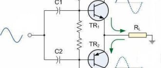
The basic principle of a current-controlled amplifier was first described in The Elector (see Elector #8 and 21).
To briefly summarize, his circuit uses the effect of the four passive components (bridge) R2, R3, L and C, shown in Fig. 1, due to which the non-linear characteristic of the output stage becomes unimportant. Thus, it became possible to use a class B output stage (i.e., bias at the bases of the output transistors below the cutoff potential, so their quiescent current is zero) with all its advantages and without its inherent disadvantages (transient distortion) in this design. The circuit shown in Fig. 2 functionally implements the principle of current control described above. According to the author, this UMZCH allows you to get 100 W when operating at a 4 Ohm load, while Kg at a frequency of 1 kHz is stated to be 0.006% with a power of 60 W. If equipment is available that allows accurate measurements of Kg, C3 can be replaced by a 22 pF variable capacitor, and the latter is adjusted to minimize distortion.
The circuit also contains an innovation in the form of an equivalent load (R9).
The output stage is controlled (via transistors T2 and T5) by transistors T1 and T4, connected in series to the positive and negative arms of the op-amp power supply, respectively. This also improves the slew rate of the 741 op amp (meaning LM741 and clones). If, however, a faster op amp is used (such as the LF357), then the ratings of R4 and R7 must be changed to provide enough quiescent current for the op amp to keep the output transistors off.
Graham Schmidt (Germany)
Despite the fact that the idea itself, in its development, undoubtedly makes it possible to obtain the highest parameters at scanty circuitry and monetary costs, the elementary basis used by Schmidt is undoubtedly behind the times today. Today, high-precision op-amps with impressive operating speed and slew rate, powerful low-noise transistors that require almost no pairing, high-frequency diodes with a low opening threshold and inexpensive zener diodes, the voltage accuracy of which is no worse than a fraction of a percent and weakly depends on temperature, have become available. Moreover, these components are now relatively cheap and available.
Based on these facts, continuous experiments and searches, changing circuits and boards, an optimal combination of ratings and parameters of the device was obtained, the diagram of which is given below:
OU. The common TL071 was chosen as a musical, high-speed op-amp with a low bias voltage, which is very critical in this circuit, because Without C 1 , this UMZCH can actually work as a DC amplifier, since it does not contain capacitance in the OOS circuit. The best TL071 I've ever owned was an op amp from Texas Instruments®. The output offset without calibration was no more than 3 mV. For normal operation of the UMZCH, it is necessary that the output offset does not exceed 30 mV. But, since it is not always possible to get op-amps from elite companies, such as TI (Texas Instruments®), NS (National Semiconductors®) and AD (Analogue Devices®), with a low bias voltage, the board provides space for installing a trimming resistor (the value is taken from the datasheet) format CA-6V or similar.
Possible replacements (from most preferred to least):
Elite op-amps Burr-Brown, etc., TL071 produced by “low” brands such as ST, KR544UD2A, KR544UD1A, KR140UD608, KR574, etc.
Replacing the OS will also entail a change in the parameters of the LLC and local environmental protection. Capacitance C 2 is installed in order to compensate for the drop in gain with increasing frequency for op amp 741. For TL071, this unevenness appears far beyond the audio range and therefore does not require correction. One of the Vlab forum members completely excluded this capacitor. I suggest setting a capacitance of about 500 - 1000 pF for the stability of the circuit and jumper JP 1 , which allows you to disable this correction.
Zener diodes were installed in the base dividers of the Emitter Follower (EF) transistors formed by VT1 and VT2. Together with resistors R5 and R6 with a power of 0.5 W, the zener diodes form parametric stabilizers that allow you to change the power supply of the UMZCH within a wide range without recalculating the resistive dividers. For the best result, it is advisable to select zener diodes in pairs according to the stabilization voltage within 12 - 13 V, but always the same. A voltage of 15 V is unacceptable, because then the op-amp in this circuit may fail or go into an extremely nonlinear mode.
My design uses 1N4742A, as a variant of BZX55C12 or domestic ones, but they require selection, because their spread is greater.
Diodes also meet modern trends. Together with resistors R 15 and R 16 diodes D 1 and D 2 perform the functions of thermal stabilization of the pre-output ( VT 3 , VT 4 ) stage, and also prevent the flow of quiescent current through the transistors of the output ( VT 5 , VT 6 ) stage even with significant heating of the device.
Protection diodes D 3 and D 4 are provided by 1N4007, but they are installed only if the output super-betta transistors do not have built-in ones. In my case, TIP142/147 has these diodes. When installing transistors of type 2SC5200,2SA1943, diodes D 1 , D 2 must be germanium pulse type D311 or low-power Schottky diodes; it is important that the voltage drop across the forward junction of the diode is 0.25 - 0.3 V.
Diodes D 6 and D 7 , connected in forward bias, in combination with capacitors C4..C7 prevent interference from entering the op-amp power stage, which arises due to the high consumption of the output stage at high power.
Transistors . The output stage was left unchanged; its characteristics do not matter. Popular high-frequency transistors BC546/556 were installed in the ED. R 15 , R 16 were included in the emitter circuits of the pre-output stage , helping to stabilize the quiescent current. In addition, it is convenient to measure the quiescent current using the voltage across these resistors. Its value is 20 mA . That. the voltage across the resistors should be 15 * 0.02 = 0.3 V.
The transistors of the pre-output stage were selected according to their sound. All considered options sounded approximately the same in midrange and treble, but the TIP31C/32C manufactured by Fairchild Semiconductors® (Beware of counterfeits!!!) provided not only an excellent vocal picture and detail, but also the most collected and dense bass. For the purpose of thermal stability, in addition to the measures described above, VT 3 and VT 4 are spaced at different ends of the board and each installed on a separate small plate heat sink with a surface area of about 30 cm2.
Resistors C1-4 (carbon) or MLT (metal film). All, except those indicated separately, at 0.125 - 0.25 W.
Capacitors C12 , C3 – K10-17b; C1 , C4 , C6 , C8 , C10 – K73-17; S2 – K73-9 .
The rest are electrolytes, better than well-known Japanese companies - Rubycon, Mitsumi, Matsushita (Panasonic), Samsung, Sanyo, Jamicon.
Settings
The setup is performed with the output stage transistors turned off. VT 5 and VT 6 are soldered last.
The coil is made on a mandrel d=7 mm in two layers and contains 9+7 turns of copper wire with a diameter of 0.8 mm in varnish or epoxy insulation. Impregnated with Moment glue or paraffin for rigidity. The final result largely depends on the accuracy and quality of the coil.
Balancing. To check, first set R 7 and R 8 to 180 Ohms. Connect the power to the amplifier through powerful wirewound resistors (at least 5 W) with a resistance of approximately 50 - 100 Ohms each. This will avoid possible breakdowns, overheating, power supply overload and other problems. Plate heat sinks are installed on the pre-output transistors. The input is short-circuited to ground.
Now we supply power to the amplifier and measure the DC voltage at its output. If it is less than 30 mV , then you are lucky and you do not need to calibrate the op-amp. Otherwise, a trimming resistor is installed in the board and with its help the output voltage is set to zero. The value and connection circuit of the trimming resistor are selected based on the technical documentation for the microcircuit.
The quiescent current of the pre-output stage is 20 mA. It is installed by selecting resistors R7, R8 until a voltage of 300 mV is obtained on resistors R15, R16. All these resistors must be matched in pairs with the greatest possible accuracy. Start with 180 ohms. For different op-amps and transistors, the ratings can vary from 180 to 330 Ohms. The greater the resistance of resistors R7, R8, the higher the quiescent current of the pre-output stage.
Now install the output transistors. They are attached to a heat sink with an area of about 300 cm2 through mica with thermal paste on screws with insulating bushings. Check the quiescent current again.
Bridge balance. This step can only be performed if you have an oscilloscope and a generator (can be done from a computer). 15-20 kHz to the input . First, set a small level and look at the area near the axis. If there are noticeable “deflections” of the sinusoid, then adjustment is needed. To do this, instead of C3, a tuning capacitor of approximately 30 pF is installed. By changing it, one achieves the disappearance of the area of “undercompensation”.
Check the output zero again. The setup is complete!
The printed circuit board is made of single-sided foil PCB with a thickness of 1.5 mm. Board size 90x60 mm . Below is a layout of elements and a drawing of a printed circuit board for laser ironing technology (LUT). C 5 and C 7 are installed under the board on the foil side. D 6 and D 7 – vertically.
Parameters of a correctly configured amplifier:
Voltage gain
K u : 20.5
Supply voltage U supply : ±15 – ±45 V
Rated power P at (Usupply ±30 V/4 Ohm): 100 W
Maximum power Pmax (Up ±45 V/4 Ohm): 200 W
Input sensitivity Uin : 1V
Total coefficient of all types of distortion at P = 60 W 4 Ohm, Kd : 0.006%
Amplifier quiescent current Ixx: 20 – 30 mA
Output stage quiescent current: 0 mA
Reproducible frequency band at –3 dB level: 5 – 100000 Hz
The sound so far is superior to anything I've heard. Namely: Quad 405 (Hungary), SAR Whisper, TDA7294 circuit development, TDA2050, TDA2050 ITUN, LM1875, LM1875 ITUN, LM3886, LM3886 circuit development, LM3886 Inverting connection, RRR U-7101 Hi-Fi tuning, Idol 35U-102S tuning .
Moreover, according to many who have heard Stonecold, its sound is confidently ahead of all imported industrial devices up to $800 and many after. Distinctive features are a very detailed, soulful presentation of vocal material, but without the intrusiveness and “squealing” characteristic of many amplifiers (the impression that the performer is singing just for you, and not into space). Detailed elaboration of fast group passages, collected, elastic bass. Not too deep, but more accurate than many. If you like bass that rolls in waves, powerful and enveloping, but less dynamic, put the complementary pair 2SA1943/2SC5200 at the amplifier output. High frequencies are silvery, without whistling or disruption. Detailed, thanks to a fairly low level of intermodulation. For example, in the song “Away from Me” by Evanescence, the sound of raindrops hitting metal is easily distinguishable from those falling on the ground. In the vast majority of the above amplifiers, the sound of rain simply merges into a general mess.
And yet, it’s just pleasant to listen to it for hours, it doesn’t tire you. He just gives you music... See you in a new consciousness.
Printed circuit board
Literature:
- Gumelya E. Quality and circuitry of UMZCH - Radio No. 9 1985.
- Schmidt G. Current Dumping Amplifier
I thank everyone who took part in the fate of the project. Special thanks to Leonid Shabalin , who supported me and contributed to the creation of this material.
Author: Lishmanov Nikolay aka Lincor, (Moscow)
2005
Lincor _ nobox @ inbox . ru
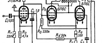
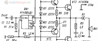
Description of the scheme
The figure shows a schematic diagram of a power amplifier:
Schematic diagram of the amplifier (click to enlarge)
The input signal through a capacitor with a capacity of 47 μF and a resistor with a resistance of 100 Ohms is supplied to the base of transistor Q1, a differential stage assembled on transistors Q1 and Q2. Low-noise transistors from Toshiba 2SA970 are used here, so it is this stage that makes the largest contribution to the final noise level of the entire amplifier.
The amplifier is covered by a general negative feedback loop, the values of the elements of which determine the gain. With the denominations indicated in the diagram, it is 24.5 times.
The negative feedback capacitor provides 100% DC coupling to maintain the amplifier output at zero potential without the need for additional integrators, etc. With a capacitance of 220 μF, it provides a lower cutoff frequency of 1.4 Hz at a level of -3 dB.
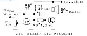
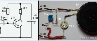
A simple homemade low-frequency power amplifier with five transistors 100-200 Watt (TIP142, TIP147)
Comments (43): #1 Vladimir January 08 2022 +21
I assembled this device. By mistake, when I turned it on for the first time, I connected the wrong polarity; one diode 4001 D4 flew out and the capacitor 220 μF 63 V C11 was pulled, replaced, the transistors all rang working 100 pounds. The result is that when you turn it on, the output is constant (the 12V light is on brightly (24 volts with reverse polarity)) and resistor R4 heats up and capacitor C2 blows. People, if anyone knows the solution, please respond, maybe the scheme is not working? who collected?
#2 root January 09 2022 +19
After such an incident, you should start checking with the power source disconnected from the amplifier, ring the rectifier diodes and measure the output voltage for each arm (+ and ground, - and ground). After that:
- Checking the installation, whether there are any unnecessary connections, whether all parts are well soldered, whether the connections on the printed circuit board correspond to the circuit diagram of the amplifier;
- Checking the ratings of all parts - it is advisable to check the resistance of the resistors with a tester, ring the diodes and transistors;
- It is advisable to replace all electrolytic capacitors; some may already be damaged without external signs of malfunction;
- Before turning on the amplifier, each power line can be temporarily connected to a light bulb designed for the supply voltage, or to a 2-3A fuse.
#3 Vladimir February 26 2022 +19
Thank you very much, I thought no one would answer. Everything is well soldered, all the details have been dialed. Maybe it’s the power supply, I took 2 windings of 12 volts from the computer power supply, and as a result of rectification I got +30 total -30 volts, maybe that’s too much?)))) Or maybe I have the wrong transistors, TIP142 and TIP147, but they’re nothing do not look like the ones here in the photo (larger in size). The most interesting thing is that when I measure the voltage at the base of one of them (TIP), one has 2 volts and the other has even around 50 volts. I'm not very versed in the radio business, I just saw it and decided to assemble the board and etched it from the printer so there can be no mistake. I even went to the service center with my device, they threw up their hands and couldn’t understand the principle of this scheme. Sorry for the wasted time and money. I understand that it was my mistake that I was in a hurry, but damn, I changed the faulty parts and everything still doesn’t work. It’s a pity that the likelihood of circuits from the Internet working is low. I think maybe it’s all 241 transyuks that are to blame or the small 556. But I changed them too))) So……..
#4 root February 27 2022 +18
As for the computer power supply - in this case the idea is not a very good one, it most likely requires a more serious alteration than just rewinding/unwinding the windings. And also, about the 12V power lines that are initially present in the computer power supply - one of them (blue wire, -12V) is designed for a very small current (0.3-0.5A). Here it is better to use at least 4 12V batteries (24+24V) or get/make a transformer with two secondary windings for a voltage of about 30V and a current of 4-6A. After rectification with a diode bridge and smoothing with electrolytic capacitors, we get a voltage somewhere in the region of 2x40V. Check diodes D2, D3, D4 with a tester; they must be of the same rating as in the diagram, this is important. It is quite possible that you are one step away from a working scheme, who knows...
Bipolar power supply diagram:
#5 Andriy August 07 2022 +20
if you can get to Omaha, you can give
#6 root August 07 2022 +19
4 Ohm, 8 Ohm...
#7 Alexander Anatolyevich March 05 2022 +19
This amplifier CANNOT be assembled! It glows like good morning. I don’t know what’s perfectly balanced in it, but it’s better to make some other circuit, for example, the Bragin amplifier 1, Troshin (modernized) Laikov, Hood, etc. etc.
#8 March March 07 2022 +24
I even went to the service center with my device, they threw up their hands, they can’t understand the principle of this scheme***** avoid this “service”... there are ignoramuses... the classic version of unch.... it’s not for them to change the module and the tank.... for unrealistic money..not understanding how it works..
#9 Pasha March 14 2022 +19
I assembled it, it works perfectly, my friend still works on his s90 4om, no complaints, easy circuit and 100% repeatability, works without setup!
#10 CcbikyH March 14 2022 +19
The signet is placed crookedly, the output offset is small, there is no temperature stabilization - it will burn out.
#11 ALEXEY June 02 2022 +17
Collected. Operates on 40 volt input. The power is pretty good. But I tested it without radiators and as a result, after a minute of operation, all the transistors burned out. So don't even try to run it without additional cooling
#12 Master April 06 2022 +14
Collected on TYPES. It played great, the power was about 36 volts +/-, together 72 volts to make it clearer, the power was taken from an old VCR. TYPES burned out even with the radiator... I changed and also installed 2 coolers from the computer. I made a separate switch so that they do not make noise when you need to listen quietly. In general, good airflow is needed at high volumes. The scheme is great. The lightest and very powerful. Even I, without experience, managed to assemble it for the experiment.
#13 ANATOLY June 23 2022 +16
Please tell me what diodes D5-D8 are for, what function they perform by shunting resistors R9-R10.
#14 Seawar June 24 2022 +11
Anatoly. Singingly, at low voltages, resistors are used to ensure linearity and stability until awakening, and at high signals, such a resistor value will lead to great heat losses, reducing the maximum voltage, so the resistors are shunted with diodes. This deteriorates linearity, but at great levels the signal already becomes unmistakable.
#15 ANATOLY June 25 2022 +11
Seawar thank you. I caught the general meaning, but if someone who speaks Russian will explain a little more and answer the question: Is it possible to include diodes like in the D5-D8 diagram in the Odyssey u-010 UM. I will be grateful.
#16 Artem August 27 2022 +8
I assembled everything clearly, checked everything (sort of), but it doesn’t produce the slightest sound, the supply voltage is from a 24V transformer, after the diode bridge with a slightly larger conduit, maybe there is not enough power? What’s the problem? who knows? What is the minimum voltage for this circuit?
#17 root August 28 2022 +9
Hello, Artem. You have two secondary windings of 24V each in the transformer, after the rectifier and capacitors you get approximately 33V+33V, at the terminals of the diode bridge - 66V. Theoretically, the circuit should operate from such a supply voltage. Check the printed circuit board with the circuit, check that all transistors and diodes are working properly, and carefully check that all other parts are installed correctly.
#18 Artem August 28 2022 +8
Transformer TP 112-16 secondary one for 24 V transistors called all the working circuits, redid everything thoroughly and everything was clear, I noticed such a thing on type 147 there is voltage but 142 there is no. As I understand it, you need two secondary ones? And immediately if you take a transformer TP 115-k12, two secondary 18V 0.5 A, will it fit or do you need a more powerful one?
#19 root August 28 2022 +7
Artem, first of all, look for information about what a bipolar power supply for an audio amplifier is and how it works.
Figure 2 and the comments show the power supply diagrams for this amplifier; it shows that 2 secondary windings are needed! A transformer for this ULF needs a power of 250-300W or more, this is also indicated in the article.
The TP-115 2x18V 0.5 A you proposed is a power of approximately 18-20W, this amplifier will not even “sneeze” with such power.
We can recommend that you put this circuit aside for a while, since you will have to work in it with fairly high supply voltages 48V + 48V = 96V, given the lack of much knowledge and experience, this can be very dangerous!
Study all the necessary questions, understand the operation of circuits, safety precautions when setting up powerful sound amplifiers, and then return to setting up this ULF.
#20 Artem August 28 2022 +9
I have already assembled some circuits, at the moment I am switching to powerful ones, which means I need a 2 x24 1.5 A torus at a minimum, I understand
#21 Alexander September 22 2022 +7
I assembled the amplifier and copied this board, it works smoothly and clearly without distortion, the details are all according to the diagram. The frequencies are pleasing and the sound is powerful, thanks to the creator of the circuit for this amplifier.
#22 rafick January 25 2022 +12
I also assembled it, but did not find the necessary parts in my store. Instead of TIPs I used kt8101a + kt503e and kt8102a + kt502e. Instead of BD241C - 2SC2073. Diodes are different. Plays great at 2 ohms. There is a tda7294, so the transistor one does it in all respects - there is bass and no audible distortion. The radiator is cold at low power. At first it was warm, but having overcome the excitement, it cooled down.
#23 Sergey February 10 2022 +6
Help me recalculate the resistance of this ULF for power supply from a +-24V source
#24 Solderer March 30 2022 +2
There are a lot of details. Something simpler.
#25 root March 31 2022 +3
Where there are fewer parts and it’s simpler, you can choose something from audio power amplifier circuits on microcircuits.
#26 Oleksandr May 05 2022 +5
I assembled this amplifier just for the sake of experimenting when I had nothing else to do. True, according to a slightly different scheme:
It worked immediately after assembly. Moreover, he has already been working in the club for two years and pumps speakers of 250 W each (LF 15″ 200 W + HF 50 W). Power supply +/- 45V from transformer power supply. A fan is installed to cool the radiator. If anyone is interested, I can take a photo.
#27 root May 05 2022 +8
Hello. I think many people will be interested in a photo of the finished version of the amplifier.
#28 Oleksandr May 06 2022 +4
OK. Tomorrow I'll go to the club and take a photo.
By the way, I have now made two versions of the amplifier seals according to the diagram from this site. I was just wondering if the sound (power) would really be different due to the fact that several parts were added to the circuit. I'll write about it after the comparison. I'll post the photo right away.
#29 Oleksandr May 08 2022 +2
And now attention to the question!!!!!!Is capacitor C3 turned on correctly????? If I'm not mistaken, then it should be connected in PARALLEL to resistor R5. Or I'm wrong?
#30 Oleksandr May 08 2022 +5
By the way, the promised photos:
The amplifier is soldered on a printed circuit board from a power amplifier with a similar circuit..
#31 Oleksandr May 09 2022 +3
So I started assembling this amplifier and when it came to the BC556 transistors, an embarrassment surfaced. Almost all datasheets indicate the location of the pins as KBE E, but my test shows E B K. I started searching and found a datasheet with pinout E B K. Datasheet (almost all of them are like this) KBE https://html.alldatasheet.com/html -pdf/532902/FAIRCHILD/BC556/484/1/BC556.html Datasheet EBK (rare) EBK https://html.alldatasheet.com/html-pdf/339623/RECTRON/BC556/292/1/BC556.html So that those for whom this amplifier does not work, try deploying the BC556 transistors. After assembly, I’ll try to deploy the BC556 transistors and see what happens. Then I'll write back.
#32 root May 09 2022 +2
In the author’s original article, capacitor C3 is included this way. The author pointed out that components C3, C5, C6, C7, C9, C10, C11, C12 and R11 on the amplifier board serve mainly to prevent self-excitation and suppress interference. In some power amplifier circuits on TIP142, TIP147, a capacitor with a capacity of 15-47 pF is placed in parallel with the feedback resistor (R5 in Fig. 1). You can try adding it and selecting different containers to listen to what changes.
The article has added a pinout for BC556B-D transistors, and also attached a datasheet from onsemi.com. If there are doubts about the pinout of the transistors available, then they can be checked with a multimeter and installed in the board in accordance with the circuit diagram.
#33 rafick May 10 2022 +1
Has anyone measured the parameters of the wuxia?
#34 Sergey May 15 2022 0
The guys assembled this amplifier, exactly the same, it works from +/- 19 volts, if I connect +/- 37 volts to it, it works until the track is switched, while the track is switched, there is a click from the phone itself (playing from the phone), and the output goes out cascade with fireworks. There are no errors in the circuit, I checked everything 100500 times. What do you advise?
#35 Alexander Compromister May 16 2022 0
The click is constant; the output flies out from the through current. Somewhere a galvanic isolation is needed.
#36 rafick June 11 2022 +1
Sergey, perhaps this click is causing self-excitation at high frequencies (>1 MHz). A through current occurs precisely in this case, but not from a constant current. This is possible on some speakers with a crossover, in which the resistance at high is very high. In such cases, a Zobel-Boucher circuit is installed at the output of the amplifier. The circuit must be supplemented with inductance and a resistor. May I help.
#37 Serge December 02 2022 +2
I assembled this device according to the diagram (# 26 Oleksandr). Everything works great... But there were some nuances during the design process:
- Q4 and Q5 are a differential stage; it is MANDATORY to select these transistors with the same beta (current transfer coefficient h12). I also took KT3107I, VS327-40, S9015. It all depends on the ULF power supply;
- I used stabilized and non-stabilized power supplies - the capacitance of the power supply capacitors should not be less than 4700 microfarads in the arm;
- Instead of Q3 (TIP41) I took KT805 - it works;
- The input capacitor C2 is by no means an electrolyte - ceramics, film, 1, 2, 3 uF, but the bass will weaken a little;
- The result was better when instead of TIP 147 - 142 I installed MP1620 and MN2488 at the output;
- R1 - set a trimmer to correct (0) at the output.
I made the sign myself, it’s a little different)) [email protected]
Printed circuit board -
.
#38 Serge December 02 2022 +3
I'm not a pro, I'm learning! And I gain knowledge by experimenting... With scheme No. 1 it was more likely not an experiment, but a mockery))) I changed EVERYTHING FOR EVERYTHING, and the scheme worked...!!!. I changed different complementary pairs of transistors, the values of all capacitors and resistors, of course within reasonable limits. And circuit No. 1 still produced a musical sound (sometimes excellent, sometimes distorted).
And as for an amateur: a reliable, cheap, simple circuit with excellent musical characteristics, unpretentious in settings...
Best result of the experiment:
- Output transistors - (MN2488 and MP1620); C1- 47 microfarads; Q3-D2396 (beta > 1000);
- diff. cascade - BC 557C (select according to the same beta: >400);
- 5 W emitter - 0.15 Ohm;
- C2- 10 µF, but it must be ceramics or film but not electrolyte (2 µF, 3 µF is possible, but the bass will be slightly weakened),
- R1 - 1K and preferably variable to set “0” at the output;
- R5..R3- 2.4 K —- 3.9 K (selected for output transistors);
- everything else is as in the diagram.
Good luck, experiment!!!
PS I’m already soldering the fifth copy))) Friends are inundated with orders)))
#39 NIKOLAI70 March 07 2022 0
Transistors TIP142 TIP147 P=125W AND Uk-e=100V HOW IS IT POSSIBLE TO DOWNLOAD 250-280 WAT FROM THEM FROM ONE PAIR? and power supply +- 48v is the maximum for unstabilized power supply. output maximum 150 watts at 4 ohm load
#40 Sanya April 28 2022 +2
Hello, I am a beginner radio amateur (just a beginner). Can anyone explain approximately how this circuit works and what it's for? I will be grateful
#41 root April 29 2022 0
Hello. Briefly: the diagram shows a push-pull low-frequency power amplifier. The input is built on a differential stage of T1 and T2, which controls the second pre-amplifier stage, assembled at T3 and connected in a common emitter (CE) circuit. This, in turn, controls a push-pull cascade using powerful composite transistors T4 and T5, which are connected according to a circuit with a common collector (OC). The load of the output stage is the speaker coil.
What is a “push-pull power amplifier”, “a differential stage in an amplifier”, “connecting a transistor with a common emitter”, “a transistor and how it works”...etc. - search and read in the literature and other articles on the topic.
This scheme cannot be recommended for beginners! Here you will need experience and some skills, for example, in assembling a simple bipolar power supply. You will need to work with high voltages and currents, and without understanding the operation of such circuits and the ability to set them up, this can be dangerous.
In the “Transistor ULF” section there are circuits of the simplest push-pull ULFs.
#42 Sam June 02 2022 0
The scheme is clumsy, nothing good will come of it. take at least resistors R9, 10. 1 ohm 1 watt. what kind of 200 watts can there be? maximum that. these resistors will withstand 15 watts, and even then hardly. . The author of this scheme seems to be a complete ignoramus. and what’s even more surprising is that so many people are trying to repeat this nonsense, and then write in bewilderment, why is everything burning? ! . Yes, one differential cascade is ignorant nonsense. who knows what is missing in it and what is superfluous, they will understand why all the transients fly out.
And those who write laudatory defmrams for this scheme, allegedly repeating it, and how musical it is, show people what you have collected there, record a video on how it all works.
#43 Maks December 14 2022 +1
Before writing about resistors R9,10, you need to measure the voltage drop across them, and not turn on the smart guy! All the specialists here are such idiots)))
Feedback capacitors
The capacitance of the capacitors at the input and in the negative feedback circuit is slightly larger than is usually installed in these circuits. These values are chosen to minimize possible distortion in the audio frequency band.
For example, the output impedance of a CD player is typically several hundred ohms. If you install a capacitor with a capacity of 2.2 μF at the input (typical value for input circuits), then at a frequency of 50 Hz the input stage will “see” the resistance of the signal source of about one and a half kiloohms. A capacitor with a capacity of 47 uF at the same frequency will have an impedance of only 67 ohms. (Remember that the signal source is essentially a voltage generator, so it must have a low output impedance)
It also does not use (usually recommended) non-polar capacitors. They are several times larger in size than simple electrolytic capacitors, which is why they tend to pick up more noise and interference. Since the goal is to make an amplifier with a minimum level of noise and distortion, all measures have been taken for this: circuit solutions, choice of element base, design solutions.
The amplifier has a wide bandwidth, which also imposes its own requirements and restrictions on the selection of elements, installation, etc. in order to minimize picked up noise and interference.
Diodes D1 and D2 protect the relatively low voltage electrolytic capacitor in the negative feedback circuit if the amplifier fails. By the way, it is strongly recommended to equip the amplifier with some kind of speaker protection system. The authors migrated it from the previous design, so its description is not given here.
Using two diodes instead of one guarantees the absence of non-linear distortion due to the limitation of signal peaks in the feedback circuit (about 1 V, and two diodes will give a limitation at a level of about 1.4 V).
Amplifier “Troika” (2+1) ZK-TB21 50W*2+100W TPA3116D2. Share and enjoy.
Instead of the epigraph: “AUDIO LABORATORY. Engineers are strictly prohibited from entering!”
Much has been said about the advantages of sound reproduction systems in which the low-frequency section is made as a separate unit. The systems are convenient, are in deserved demand, and demand, as we know, generates supply. As for the Aliexpress platform, there are a lot of offers, just choose according to your taste. But, as they say, if you don’t feel it, you won’t believe it. So I decided to touch it. I looked at Ali. And there in the bestsellers ZK-TB21 50W*2+100W, a new product. Moreover, I got a five-day ten percent discount. We must take it. I took it. Three weeks later the DIY kit arrived. Do you like music? Then please go to the music room, friends. Move your chairs closer!
What is it? The device is designed for three-channel audio signal reproduction. Two stereo MF-HF channels and one common low-frequency (LFE) channel. The signal source can be connected to the device either via Bluetooth (5.0 declared) or via a physical circuit using a cord with a 3.5 mm plug. The device can be powered from a DC source in the voltage range of 12-24 volts. To fully realize the declared characteristics of this board, the power of the power supply must be less than 100 Watts. That is, to provide a current within four to five Amperes. As practice has shown, for comfortable sounding of a room 6-8 sq.m. Even a 12 Volt/1 Ampere power supply is sufficient. Of course, with appropriate speaker sensitivity. Power can be connected to the board either through a standard 5.5/2.1 (2.5) plug, or via a two-wire line through a two-pin connector. The power circuit is equipped with protection against polarity reversal - Schottky diodes SS54. On the board there is a six-pin screw plinth (terminal block), to which the speaker wires are connected and secured with screws. Electrical part of the circuit. The final amplifiers are class “D” integrated amplifiers, implemented on the well-known TPA3116D2 microcircuits. One of the microcircuits contains a two-channel stereo signal amplifier, the second one contains a single-channel amplifier for the low-frequency channel, here the microcircuit is connected according to a circuit with doubling the output power. The preamplifier and crossover filters are based on NE5532 operational amplifiers. Four amplifiers in each channel. The following adjustments are available to the user. Adjusting the signal level. Since loudness compensation is not provided, and the regulator has a linear characteristic of type “B” (Latin!), I cannot call such an adjustment a volume control. Unless RMG is a maximum volume control. Adjustment of treble and bass in stereo channels. Adjusts the level and cutoff frequency of the low-frequency channel. We will see the depth of adjustment later. More on this below. To be honest, I was hoping that the separation of the bands would be organized by a crossover filter with an adjustable crossover frequency. In vain. This is a low-pass filter, albeit with an adjustable cutoff frequency. The band of stereo channels is simply limited from below by a high-pass filter, so using the board as a two-channel amplifier will not work due to the low-frequency rolloff. The Bluetooth radio module uses the AC20VR07277-25A4 microcircuit. There is zero information on the building on the Internet. But as far as I understand, this is a kind of universal 32-bit audio processor that allows you to play anything, including USB and solid-state drives. If anyone has dealt with it in detail, please post in the comments. I understand that this part of the story was very boring. But it’s also impossible to live without her.
So, let's see
what came to us?
Let's be tight-lipped here. This is the box in which the device is packaged.
There are contents in a bag inside the box. We bring it into the light of day.
Here the board is in a neat little bubble wrap, and in a sealed bag there is a disassembled case, mounting posts, screws, control knobs, a two-pin power connector and a screwdriver, so that the DIYer eager for hands-on work will not have the slightest problem in assembling the amplifier case.
Here it is, the treasured design. We'll collect it and take a closer look. For now, that's it.
And here are the electrical parameters of the device.
And so the output power depends on the supply voltage of the device.
A preliminary acquaintance took place. It's time to put it all in a box. Fortunately, everything necessary for this was carefully provided by the seller and does not cause any difficulty. And at the same time, let's look at the board in detail.
The payment is in front of us. Next to it is a set of stands and screws with which we will install the upper and lower panels of the case.
View from below. To be honest, there was an attempt to copy the montage, but... “abandon all hopes...”
Sound processor, Bluetooth antenna, physical connection plug connector.
Power connectors. Plug and two-wire socket. By the way, a protective diode is installed in the circuit of each connector. It turns out that if you apply a variable from a transformer with a midpoint to each of the inputs, you can get a full-wave rectifier. There is a filter capacitance on the board. But so far this is just an idea, not confirmed by practice. Looking ahead, I will say that the amplifier also works with an AC amplifier. The result is a half-wave rectifier. Yes, the background appears slightly. But there is a possibility.
And this is our speaker plinth. Everything is written out in detail on the lid, you won’t get confused.
Pre-amplifier and filter block. Everything is clearly and clearly marked. I have already put the handles on the variable resistor axis. The power filter capacitor is visible. 6800uF/35V. Considering the maximum supply voltage is 24 Volts, OK!
Did you already have a view of the plug socket and Bluetooth antenna? Ah, not from this side.
And here are our racks. Big and small.
And body panels.
We install long racks.
And short stands.
Before closing the panels, let's evaluate the radiator. Common for two buildings. Radiator size 50x25x10 mm. Secured with one screw to the board. It is attached to the housings using thermal paste.
Front panel. Yes, the dimensions are small, I won’t say that it’s convenient to operate. But a compromise is a compromise.
And this is a little blue eye. I turned the level control knob to the right - the switch clicked and the LED lit up.
That's how it caught fire.
This is what we got as a result. The device dimensions are 118x100x25 mm, including control knobs, and weighs 195 grams.
Then the overview and assembly part of the story came to an end. It's time to test the device in action. Test the amplifier.
REM: Yes, but what happens if I ask a basic question to the Audience: “What is an amplifier?” I'm afraid many will look with bewilderment, but will think about it. An amplifier is a device that converts the energy of a power source into a high-power output signal, identical in shape and type to a low-power input signal. Something like this, if I remember correctly. Eh, I passed the coursework on amplifiers about half a century ago... (smiley!)
Well, what are we going to connect all this to? We need to make loudspeakers. As satellites, I will use loudspeakers based on broadband heads from RCF with a sensitivity of 91 dB, nominal/musical power of 6 W/10 W, reproduced frequency band of 90 Hz-20 kHz and frequency response unevenness of 10 dB. The heads are installed in closed boxes measuring 24x24x11 cm. As a loudspeaker for the low-frequency channel, we use a slotted phase inverter based on 25-GDN-3-4, assembled in three free evenings and still with an unkempt appearance. The design is freshly made, so you still need to think about what color and what to give it. There is film and putty too. Or maybe just order fabric covering from Ali and... I’m still thinking. Maybe I’ll even tell you about the process. Therefore, for now, we will hide it on the closet and put it in the far corner away from prying eyes, so that it does not get underfoot. That's why it was made small - 22.5 x 22.5 x 32.5 cm, made of 22 mm thick chipboard, and the sound from the corner will reach the ear even better.
But this unit has such a frequency response in terms of sound pressure in the range of 30-600 Hz.
More detailed frequency response in bass reflex (red)/closed box (green) modes. Clickable, 0.5 dB grid.
During the experiments, I connected two four-ohm loudspeakers in parallel (“Saltykov cubes”) as LFEs. The amplifier endured this with dignity, loudly rumbled with a booming bass throughout the apartment. Now I’ll find the recordings of Maxim Dormidontovich Mikhailov, “Drinking Song”, for example - “Pour the glasses full...” Eh...
But since “nothing comes from anywhere and nothing disappears anywhere” ©, first of all we will solve the issue with the power source. There are several switching power supplies, a small low-power regulated laboratory power supply, and a hastily assembled full-wave rectifier without a power filter. As I said above, an experiment was also carried out to power the amplifier directly with alternating current through a half-wave rectifier assembled on the board itself. When operating from all sources, the amplifier showed the same noise results. When using AC power, there was a slight AC hum that was audible, as expected. When powered from one of the switching power supplies connected to the same extension cord with the computer - the source of the audio signal - characteristic interference in the operation of the converter appeared, which disappeared when the grounding of the power supply and computer cases was separated. It looks like the land on my house is not so great. And the measurements here are annual, however. Anyway. Optimal power was determined to be 19-20 volts. With a higher supply voltage, the temperature conditions leave the best - the radiator at 25-26 Volts cannot be held by hand even at idle. It seems that if there is a need for maximum power output from the amplifier, you need to increase the radiator area or blow out the existing one. So, we connect a 19V/4.75A power supply to the amplifier. This is sufficient for my purposes. The food issue has been resolved. We turn on the amplifier and first of all evaluate the noise characteristics by ear. With the regulator set to maximum sensitivity mode, the noise, alas, is clearly audible. Since the only weighing filter in my conditions is my own ear, there is nothing else to do but trust it. In the middle position of the level control, noise is not perceptible to the ear even at a distance of fifteen centimeters from the loudspeaker. Now, this is already pleasing. Shall we give a signal? We connect the phone to the amplifier via Bluetooth. Thank God, there is no prompter speaking in the Chinese dialect. But there is a characteristic “ta-dam!” Well, there is a signal, so there is. It appears both when Bluetooth is connected and when it is disconnected. And this, in principle, is necessary. Bluetooth is defined as “BT-WUZHI”. Well, “that’s his last name,” as the unforgettable cartoon character used to say. Everything would be fine, but there would be a fly in the ointment. When playing in quiet areas of the phonogram, a characteristic noise like “fat in a frying pan” is heard. Noise is present regardless of the signal source and the type of power supply. It is masked by a high level signal. So pop music lovers need not worry. But listening to this kind of hissing on fragments of a soundtrack when playing music with a wide dynamic range is unpleasant. Interference is also noticeable when reproducing speech, for example, listening to an audiobook. In general, it seems that the circuit contains something like a threshold noise suppressor. As soon as data transmission stops, the speakers are perfectly silent. But the characteristic operation of the noise suppressor is felt and attracts attention. Alas, I was not pleased with bluetooth. True, the case helped to minimize the interference. Having accidentally touched the antenna with a screwdriver, I noticed that the noise disappeared. I soldered an additional antenna to the existing one.
The “frying lard” disappeared in the pauses. But, alas, it is not possible to eliminate the operating noise of the microcircuit itself and the noise suppressor noise. The on-air interference was removed, but the hardware interference was not. In addition, such a hastily modified antenna made it possible to expand the Bluetooth coverage area. Now even three walls are no barrier to him. And with the “native” antenna it was no more than five or six meters. Here. Now, it looks like we'll have to find a connector and install an external antenna. Oh, this rationalization! But what can you do if there are improvements with it?
Next is AUX. As far as the physical circuit is concerned, everything is perfect. The main thing is to select the input signal level and set the sensitivity of the amplifier. Right now I’m listening to wonderful jazz. Fabulous! Switching between bluetooth and AUX is automatic. Bluetooth is a priority. That is, if two signal sources are connected - one via Bluetooth, the other via a cord, then the signal connected via Bluetooth will be played and will not switch to AUX until Bluetooth is turned off on the source. When you turn off the Bluetooth, the amplifier will automatically pick up the AUX signal.
Well, let's put REW on the computer and at least somehow see what happens when we rotate the adjustment knobs back and forth? I don’t have a measuring microphone, so I can’t rely on absolute values. But relatively, and in the world, as we know, everything is relative, you can imagine what is happening. Let's quickly and with one eye. We should listen, not...
First, let's look at what happens with the HF tone control. Red - the regulator is in the minimum position. Green - in the maximum position. So what do you think? Upward adjustment depth - 26 dB! People, this is twenty times higher! To be honest, I have no idea what it is for. The “malicious user” will turn the knob “all the way to the right”, and then “this is not an amplifier, its tops look like metal, there’s solid sand there. How can you even listen to this class “D”?!” Well, what does class “D” have to do with it, huh? What was surprising was the almost complete lack of effectiveness of low-frequency control in stereo channels. Changes seem to occur by ear, but it is impossible to catch them with a microphone with obvious noticeability. One gets the impression that the circuit uses a standard passive bridge tone control, but it is installed in the path before the high-pass filter of the stereo channels, which reduced the effectiveness of this control to almost zero. Without a diagram, it is impossible to determine exactly. Well, okay. We have a full LFE channel here, so...
But we get such nice lines when we adjust the cutoff frequency of the low-frequency channel.
Let's zoom in. Green - middle position of the low-pass filter cutoff frequency control. And the blue one, as you may have guessed, is the frequency response of the satellites. The manufacturer deceived himself a little and played it safe. The unevenness turned out to be only five to six dB instead of the declared ten, that is, twice the sound pressure, not three. But I warned you above - the microphone is not a measuring one, there is no calibration file.
Alas, I did not remove the frequency response when working with satellites of a different type. But I note that the timbre coloring of the sound greatly depends on this adjustment. Much depends on the soundtrack. So there is no ready-made recipe here. It all comes down to your preferences, speakers, and placement of the speakers in the room. Sometimes it even makes sense to “play around” with the phasing of the low-frequency channel loudspeaker. Devices of this type, but of a higher class, provide a phase regulator for the LFE channel. This makes sense if the woofer is installed at a distance from the speakers of the stereo channels.
Well, we looked at the operation of the device as such. But there are other uses for this amplifier. For example, you can use it only as an amplifier for the low-frequency channel, and turn on the satellites through another amplifier. To do this, simply connect two amplifiers in parallel at the input. Not bad either, checked. And there is a third option. In it we will separate the LFE and stereo channels in software. We will connect our ZK-TB21 to the “SUB” output of the sound card in mode without satellites, and we will connect our (what kind of one do we have? At least a tube!) stereo ULF to the audio output of the sound card. Of course, you have Linux Mint 20.1 installed.
Here it is, however. We talked about everything, but not about the source of the amplified signal!
So, open a terminal and install Gedit. Actually, it’s possible in any other editor, but I like this one the most.
sudo apt-get install gedit
Then we edit the Pulseaudio config file:
sudo gedit /etc/pulse/daemon.conf
Before doing this, you should ask the system about supported resampling methods. However, if this terrible word causes cognitive dissonance in you, and the words “resampler” and “evil” are identical concepts for you, then you don’t need to do this. We'll just simply turn it off.
pulseaudio --dump-resample-methods
and see what we are offered to choose.
So, we opened the config and found the line in it
; resample-method = speex-float-1
We erase what is written there and write:
resample-method=copy
and remove the semicolon. That's it, screw the resampler. But if necessary, choose the one you like from the dump. I recommend soxr-vhq or speex-float... why bother, we prescribe speex-float-10. Just keep in mind that you will give up to thirty percent of the performance of a four-core processor to this codec.
Have you registered? Super! Let's continue and write this:
default-sample-format = float32le default-sample-rate = 44100 alternate-sample-rate = 48000
Now you can save the changes, restart your computer and feel the difference. Or not feel it.
But that's not all. You need to select the LFE channel and set the crossover frequency of the stereo channels with the subwoofer channel.
Open the “pulse” config again and do the following:
remixing-produce-lfe = yes remixing-consume-lfe = yes lfe-crossover-freq = 200
Save, reboot.
This is “lfe-crossover-freq = 200
»—crossover frequency of stereo channels and subwoofer. In this case - 200 Hz. Enter the number you need.
After all this, connect the ZK-TB21 to the “SUB” output of the sound card, and your favorite amplifier to the linear output. That’s it, “here’s the troika rushing…” The main thing is not to forget to switch the system to the “Analog surround 2.1 output” mode by selecting it in the “Sound Settings” menu. All options have been tried, tested and work great. The sensitivity of the loudspeakers can be leveled both by the controls on the amplifiers and by the graphic engines in the sound settings.
It looks like it's time to summarize the story and come to certain conclusions.
Yes, the device does not claim to be “high fidelity”. Nevertheless, as a multimedia sound reproduction system it fully justifies itself. There are no complaints when connecting the signal source via a physical circuit. The class and price of the device fully meets the requirements for such systems. But playback via a radio channel, alas, leaves much to be desired. Perhaps this is a problem with this particular circuit design, the fact remains. To draw comprehensive conclusions, you need to consider, test and compare several different types of devices. There is no such possibility yet. But compactness, efficiency and accessibility do their job. This amplifier is one of the best-selling amplifiers on Aliexpress, and it’s up to you to decide whether to buy it or not. I did not get the desired playback quality via Bluetooth. As for connecting via a physical circuit, the result here depends only on the quality of the source signal. And, perhaps, the main and, at least for me, the main conclusion. The claims made do not apply to the TPA3116D2 class “D” integrated power amplifier. I have no complaints about him. All claims made here relate to a specific device based on this chip. Namely, to the circuit design and implementation of the pre-amplifier. The final amplifier itself does not cause any complaints. I think the bulk of the complaints about this class of amplifiers are caused primarily for this reason. And if it weren’t for my perfectionism in relation to the Bluetooth channel, then everything would be fine.
PS
“While the issue was being prepared for printing,” I revised some of the conclusions regarding the operation of bluetooth. After modifying the antenna, the interference, yes, decreased significantly, but remained. Only now it can be heard at a distance of no more than twenty centimeters from the loudspeaker. It is inaudible at a distance of more than a meter. So the device can be safely recommended for purchase. A tablet connected via air to an amplifier, a magnificent Relaxing Jazz on YouTube... what else is needed for a wonderful quiet winter quarantine evening while there is a curfew outside? Oh, I have something that I “still need,” I’ll pour it now. Ten years is a remarkable endurance. And the sushi will be delivered now.
PPS Well, mechanical contact in the path has made itself felt. And only about a month has passed. Rustling noises clearly appeared when adjusting the timbre and volume. Potentiometers are useless. Mechanical contact in a signal circuit is still archaic. And this is how it ended in the end.
R.R.P.S And finally, one more funny observation. AUX/Bt switching occurs automatically here. That is, as soon as the amplifier connected via AUX detects a Bluetooth signal, it immediately tries to connect to this Bluetooth, signaling the presence of a signal with a loud “Thu-lyu-lyu!” and briefly turning off AUX. And now I know when my upstairs neighbors return home - there are two students renting an apartment and always walking around with Bluetooth headphones. When my neighbor on the left comes home from work, when anyone walks along the site past my apartment with Bluetooth turned on. Straight out spy passions! Fortunately, at least confirmation is required to connect. Otherwise I would listen to all the music in the house.
Driver cascade
The main voltage gain is provided by the cascade on transistor Q9. To reduce nonlinear distortions, the input stage is decoupled from the driver stage through an emitter follower on transistor Q8.
To obtain maximum linearity and maximum gain, the driver stage is loaded onto an active current source (made using transistor Q7). The base bias for both it and the input stage current source (Q5) is created by transistor Q6. The somewhat complex bias circuits of transistors Q5, Q6, Q7 provide maximum suppression of noise and ripple in the power supply circuits, which is important for a class “B” amplifier, where large (up to 9 A!) and, most importantly, asymmetrical pulse currents flow along the power buses.
If the ripples of the power circuits get into the input stage, they will be amplified by all stages and will end up in the load - the speaker system. We most likely will not like what we hear as a result. Therefore, the amplifier has taken all measures to prevent the penetration of noise and ripple from the power circuits into the amplification path.
The oscillogram in the center shows a 1 kHz oscillator signal. The upper (red) graph is the ripple modulation of the positive power supply bus by the input signal, the lower graph is the modulation of the negative power bus:
A 100 pF capacitor between the collector of Q9 and the base of Q8 limits the amplifier's bandwidth. Since it is subject to the full amplitude of the stage's output, it must be rated for 100 V or more.
Output stage
The output signal of the driver stage on transistor Q9 is fed to the output stage transistors through 100 Ohm resistors, which protect transistors Q7 and Q9 from a short circuit at the amplifier output, although, of course, the fuses should blow first. In addition, these resistors prevent possible excitation of the output stage.
The output stage is built on composite complementary Darlington transistors. Firstly, this made it possible to use highly linear transistors from ThermalTrak with built-in diodes, and secondly, to obtain the maximum full power at a 4 Ohm load (to minimize the voltage drop across the output stage).
Thermal offset compensation
When using four Thermaltrak transistors in the output stage, we have four built-in diodes to organize a temperature-compensated bias circuit.
As shown in the diagram, four diodes are connected in series between the collectors of transistors Q7 and Q9. This method of organizing the bias of the output stage was widespread in the 60-70s. Later it was replaced, which became a classic solution, by a voltage multiplier on a transistor.
Typically, the quiescent current of the output stage is set by a stage on a transistor, which is mounted on the same heatsink with the output transistors, thereby ensuring thermal coupling. This method has disadvantages: firstly, the bias circuit transistor must be selected to ensure optimal thermal compensation, and secondly, in any case, thermal inertia is present: the output transistor must heat the radiator, the radiator will heat the bias circuit transistor, and only then will thermal compensation of the output stage current occur.
Placing diodes for thermal stabilization in the same package with the transistor solves these problems: the diodes have characteristics that are maximally consistent with the transistors, so thermal stabilization occurs as accurately as possible, and secondly, they are located on the same substrate with the transistor crystals, which makes them heat up as quickly as possible, eliminating the intermediary radiator.
With Thermaltrak transistors, thanks to the built-in diodes, the amplifier's quiescent current quickly stabilizes after switching on and is maintained very accurately, regardless of changes in supply voltage or output signal level. The manufacturer also claims that the linearity of the cascade with such a bias is higher than when using a conventional transistor multiplier.
The figure explains how to set the output stage bias:
Four integrated diodes compensate the four base-emitter junctions and determine the output stage current. Taking into account the fact that the output transistors are connected in parallel and 0.1 Ohm resistors are installed in the emitter circuits, four series-connected diodes provide a quiescent current of the output stage at a level of 70-100 mA, which is slightly higher than usually set by the transistor bias unit.
Output filter
The output filter is an RLC circuit consisting of an inductance (without core) of 6.8 mH, a resistor with a resistance of 6.8 Ohms and a capacitor with a capacity of 150 nF. This filter has been used by the authors in many amplifier designs and has been shown to be highly effective in isolating the output stage from any reverse currents caused by a reactive load, thereby ensuring high amplifier stability. The filter also effectively suppresses RF signals picked up by long speaker wires, preventing them from entering the amplifier's input circuits.
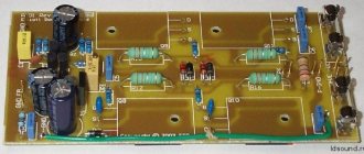
Double sided PCB
To simplify and optimize the wiring of power circuits, the amplifier's printed circuit board is double-sided. Firstly, this made it possible to organize the wiring of the common wire in the form of a “star”, when all conductors with zero potential converge at one point, which eliminates the formation of “ground” loops and the penetration of the output signal into the input circuits. We wrote about this in the series of articles “A little about amplifier power supplies”
Secondly, and more importantly, the wiring and placement of parts on the board are designed to compensate for the magnetic fields created by large pulsed currents. We also wrote about this in a series of articles “A little about power supplies for amplifiers,” where it was proposed to twist bifilar conductors with large and antiphase currents. You can’t connect conductors like that on a printed circuit board, but it is nevertheless possible to compensate for fields.
As an example, the positive power supply fuse is located adjacent to and in parallel with the output stage emitter resistors Q12 and Q13. The elements are connected in such a way that current flows through them in different directions, due to which mutual compensation of magnetic fields occurs. Similarly, the parts are placed along the negative bus.
The power paths from the CON2 connector to the fuses run side by side parallel to each other, and in the middle of the board they diverge in different directions. Under the diverging conductors are the tracks of the emitter circuits of the output stage, and under the parallel tracks is the ground bus. Due to this layout of the printed circuit board, the magnetic fields created by these tracks are mutually compensated.
The applied methods of suppressing magnetic fields made it possible to significantly reduce amplifier distortion.
Results of measurements of amplifier parameters:
Frequency response of the amplifier at an output power of 1 W at a load of 8 ohms
Amplifier harmonic distortion at 1 kHz into an 8 ohm load. It can be seen that clipping occurs at a power of 135 W.
Amplifier harmonic distortion at 1 kHz into a 4 ohm load. It can be seen that clipping occurs at a power of 200 W.
Amplifier distortion into 8 ohm load (resistive load)
Amplifier distortion at 100 W output power into a 4 ohm resistive load.
To be continued…
The article was prepared based on materials from the magazine “Practical Electronics Every Day”
By Leo Simpson and John Clarke
Free translation: Editor-in-Chief of RadioGazeta
A decent built-in digital low-frequency amplifier with your own hands for a reasonable price
Good afternoon, Habr! Our last article about DIY audio equipment caused quite a stir, and today we would like to talk about our other development in the field of audio - high-quality ULF. The device was created by Oleg Tetushkin for his own needs. But as a result, the amplifier took root in the office. It was assembled, of course, from what was poorly lying at hand in the warehouse. In this case, it is assembled in a homemade case. But in fact, it can be built anywhere - even into furniture. What is enough imagination?
In the comments to the above-mentioned article, a debate broke out about what can and cannot be called HiFi or even just high-quality.
Therefore, I would like to clarify that the definition of “quality” is based solely on our sense of beauty. We believe that the sound of this amplifier is quite decent and will satisfy any average person. Although audiophiles may have a different opinion on this matter. This is how handsome the result should be
. What was used:
- MP5613 - Class D digital amplifier with 2 x 150 W power. PurePath HD technology.
- MP5630I2 - Indicator for a powerful low-frequency amplifier (stereo).
- MP1054 – LED dynamic dial indicator of signal level.
- MP1231 - Audio regulator 2 channels.
- ESE150-24 – Power supply. 150 W. 24 V.
- SL-01H - Heat sink with fan.
- WP4-18FB — Push terminal block 4 contacts
- LEDs 5mm – 7 pcs.
How it works?
For the MP5613, a 24V power supply was used, therefore, about 70 watts per channel will be supplied to a 4 ohm load. The result is 2*70 Watts of high-quality PurePath sound.
At the input of the amplifier, MP1231 (assembled on AD8402) are installed to operate as a volume control and balance of stereo channels, plus MP5630I2, which is used as a pre-amplifier. After this stage, the stereo signal goes to the MP5613 input, and only then to the speaker systems. As for the signal for the dynamic light indicator, we remove it from the output of the power amplifier, directly from the speaker systems.
How to do it?
Volume control on MP1231.
Basic circuit We start the process with the MP1231 + MP5630I2 input stage.
First, we connect the potentiometer MP1231 immediately before MP563012 (this is shown
. To achieve this, on the back side of the MP563012 board, immediately after the RCA connector (Fig. 1 and 1.2), you need to cut the signal conductors on the printed circuit board, stripping both conductors on both sides. The cut is made so that a potentiometer can be installed here. Important detail: it is imperative to use shielded wire to connect the potentiometer and preamplifier. All elements (probably, we don’t have to talk about this on Habré) need to be connected in full accordance with both the color and the markings.
And power is supplied to MP1231 from MP563012. Figure 2 shows this:
Fig.1
Fig.1.2
Rice. 2
A comment
: In order to improve the noise immunity of the system (MP1231 is good in everything except noise immunity), you need to slightly modify the circuit. To solve the problem, you need to follow four simple steps (shown in Fig. 3):
- Directly to the power terminals of the MP1231, together with the supply conductors, clamp the electrolyte to 1000 μF or more.
- Solder the 470 uF electrolyte in parallel with capacitor C4.
- Connect the encoder body of MP1231 to GND. Clean the mask next to the body leg and solder it.
- You can even connect the GND MP1231 and the GND of the amplifier driver with a thick wire using a braided wire. This needs to be done because the 12V source is installed on the driver. The best way to do this is shown in Fig. 4.
Housing and indicator output to the front panel
Before you begin assembling the case, you need to slightly modify the MP5613 amplifier and MP563012 indicator. The modification consists of soldering the output channels to the boards, on wires with a length of 10-12 centimeters. As for the configurator boards, there are 6 SMD LEDs installed here, which indicate the status of the amplifier: temperature conditions (2), error, readiness, overload and reset. After finalization, all this can be inserted onto the front panel of the device:
In addition, on the back side of the configurator board you need to solder a wire 15-20 centimeters long. The wire is soldered to one of the outputs (any one can be used) of each channel, through 0.1 µF film capacitors. In this way, the signal is collected from the level indicator.
Now let's start creating the body
We cut it out and glued it together from sheets of foamed PVC. We liked this material because it is very easy to process, plus it can be glued with any glue for plastic. This material is easy to paint. Here you can download files of the front and false panels (.lay format).
Parts Dimensions:
- side walls – 110 * 200
- bottom and lid – 210 * 200
- rear wall – 210 * 100
We decided to paint the body with paint from a regular can. The front panel was painted to look like metal, and the body itself was painted dark green (almost black). We attach the indicator and regulator modules to the housing using M3 screws.
We cut out a hole for the switch under the acoustic clamps, plus we drill holes for the acoustic clamps.
Logically, we place the power supply on the long side.
The amplifier is attached to the bottom through 5 mm posts. We secure the front panel using wood screws.
A comment. In order to completely eliminate interference from PWM modulation, we perform the following steps:
- We connect the GND of all involved modules in series either with a thick wire or braid;
- We attach electrolytes of 1000 μF or more near the power connectors of each module.
Now you can connect powerful speakers and enjoy high-quality sound.
If you wish, you can modernize the design of the structure. Here is a video demonstrating how everything worked:
We made the amplifier quite a long time ago, and it still serves us faithfully. Perhaps you can advise how to make the design better? The amplifier turned out to be excellent, but there is no limit to perfection, this has long been known.
If someone wants to follow our path and acquire a very decent amplifier over the weekend, all its electronic filling is here. As for the body, this is a matter of taste and the availability of auxiliary materials.
Your Master Keith