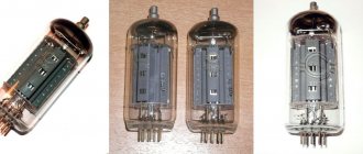
In the previous article I talked about making a simple winding machine. It's time to show manufactured transformers for lamp technology. The first was an output transformer for the JCM800 guitar combo amp. I came across good iron 0.35 mm on camber. Good section 12.5 cm2. He began to wind on his machine. I wasn’t in a particular hurry, in 2-3 hours one winding a day. Each layer was impregnated with wax using a hair dryer and a candle, so as not to cook the entire transformer in paraffin later.
Which ULF power supply circuit should you choose?
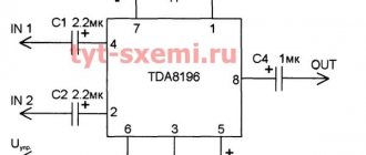
To power the microcircuit, I decided to use bipolar power.
With bipolar power supply, there is no need to deal with background noise and clicks when turned on. In addition, there is no need for coupling capacitors at the amplifier output.
Well, and most importantly, microcircuits designed for unipolar power supply and having a commensurate level of distortion are several times more expensive.
This is the power supply diagram. It uses a bipolar full-wave rectifier, which requires a transformer with two completely identical windings “III” and “IV” connected in series. Further, all basic calculations will be carried out only for one of these windings.
Winding “II” is designed to power electronic volume, tone and stereo controls assembled on the TDA1524 chip. I think I will describe the tone block in one of the future articles.
The current flowing through winding “II” will be extremely small, since the TDA1524 microcircuit at a supply voltage of 8.5 Volts consumes a current of only 35 mA. So the consumption here is expected to be less than one Watt and will not greatly affect the overall picture.
Return to top menu
Direction of turns
I had difficulty finding information about the direction of the winding turns - for this I had to refresh my school physics course (the gimlet rule, etc.). Although this question inevitably arises for a beginner.
The main rule is that the direction of the winding turns does not matter
... as long as there is a need to connect the windings to each other (series or parallel), or in the case of using a transformer in some devices where the phase of the signal is important.
It doesn’t matter in which direction you wind the turns - what matters is how the windings are then connected
Series connection of windings
When connecting the windings of a transformer in series, you need to mentally imagine that one winding is a continuation of the other, and the point of their connection is a break in a single winding
, in which
the direction of rotation of
the turns around the core remains unchanged (and of course cannot turn in the opposite direction!).
In this case, any terminal of the winding can be the beginning or the end, and the direction of rotation itself can be any. The main thing is that this direction remains the same for the connected windings.
In this case, the movement of the connected windings from top to bottom of the coil or from bottom to top does not matter (see the figure - enlarged by clicking the mouse).
In transformers in which the core is shaped like the letter “O” and the coils are wound on two frames on the right and left, the same rules apply. But for ease of understanding, you can mentally “tear” the core (from above or below), and imagine that it is straightened into one rod - this will make it easier to understand how one winding passes into another while maintaining the direction of rotation of the turns (clockwise or counterclockwise) . See the picture below (the picture can be enlarged by clicking the mouse).
Parallel connection of windings
When connecting in parallel, the length of the wire in the windings is important.
Even with the same number of turns, different windings may have different wire lengths (the winding that is closer to the middle will be shorter, and the one further away will be longer). As a result, cross-flows
.
If parallel connection of the windings is assumed, then it is better to wind them simultaneously in two (three, four...) wires. Then they will be the same length, which will eliminate cross-flows as much as possible during their further parallel connection.
Winding several wires is also used in the absence of a wire of the required cross-section (a large cross-section is collected with several smaller wires).
Checking the direction of turns using a battery and a multimeter
If you have a transformer in which you need to connect two windings in series, but the direction of the turns is not visible or known, you can apply a DC pulse from a battery to one of the windings, observing the voltage surge on the other winding.
When the voltage surge at the moment of connecting the battery on the multimeter (on the second winding) is in “+”, then the connection points of the windings will be any “+” and “-” of different windings (for example, “+” of the multimeter and “-” of the battery, or vice versa) . The other two ends will be the outputs of these windings after connection (see figure - click to enlarge).
Direction of turns on different coils
I repeat - the direction of winding is not important, it is the connection of the windings that is important.
There is one “but” though. If we talk about convenience, then on this type of transformer (with a core in the shape of the letter “O” and two coils), it is more convenient to wind the right and left coils in the same way (not mirrored, but identically). In this case, it will be more convenient to install jumpers when connecting two windings in series on different coils - the jumpers will be on one side, and not across the entire frame from top to bottom.
See the picture (to enlarge, click on the picture):
Step-down transformer assembly
A step-down transformer will have a large number of turns on the primary. In everyday life, they can often be found in power supplies, welding machines and other equipment. True, pulse units use a different technology, so repairs of such devices are carried out without transformers.
Since making a welding transformer with your own hands is quite important for homemade projects, let’s look at this option as an example. The requirements for the assembly process correspond to the previous one. A distinctive feature of such a unit is the large cross-section of the wire in the secondary winding, since the welding current can reach hundreds of amperes.
The manufacturing process is as follows:
- Use an old one or make a spool base.
- Fix the insulation layer on the transformer frame.
- Wind the primary winding with alternating layers of insulation.
- Insulate the primary and wind the secondary winding, since the large diameter of the wires will not allow you to do this manually, use a bench tool.
- Fix the terminals of both coils.
- Install the core plates.
Key differences from power
An audio frequency transformer differs from a conventional power transformer primarily in that it contains a device for passing a range of audio frequencies. Wideband ones are quite difficult to calculate, especially when it comes to impedances and when operating at high power. There is always a constant current on one of the windings. Problems with the schematic part are caused by difficulties in calculation due to the number of octaves the device operates with, rather than the range.
A pulse transformer for powering an audio amplifier takes up less space when compared with a power analogue with identical technical indicators. A generator must go to the amplifier, and to the power transformer there is only a primary winding to the electrical network, a secondary winding to the diodes and various capacitors.
Kinds
An audio type transformer operates from source resistance to load resistance. This is an undeniable axiom, regardless of what type the vehicle is - inter-cascade or output.
The sound transmission device is connected to the primary winding of the equipment. It has a resistance, the secondary is connected to it. The operating principle is further determined by the type of transformer.
Interstage
These devices are practically not produced by modern manufacturers. The fact is that the principle of their operation is based on the transfer of impulse between two resistances or impedances. This is inconvenient and leads to loss of efficiency.
Weekend
Output type devices operate not from both impedances, but from a specific source resistance. Depending on the variation of the equipment, this may be a tetrode or pentode, which are connected to an active resistance.
How to make it yourself
There are no particular difficulties or differences in the manufacture of matching transformers. The technology is similar to the assembly of step-down devices. But the following recommendations must be followed:
- The windings are laid evenly without damaging the insulation.
- The plates of small-sized devices do not require additional insulation; only the parts of the stacked cores of more powerful transformers are varnished.
- When choosing a core type, you must pay attention to the technical characteristics of transformer steel or ferromagnetic rings.
Note that independent production of devices of this type is not economically feasible. Purchasing individual components will cost more. A factory-made matching device with the required resistance transformation ratio will be cheaper.
Study of a modified transformer
Transformer TSA-30-1
turned out to be wound with aluminum wire (the letter “A” just means aluminum).
Fortunately, there was enough information about him on the Internet, although the reality did not coincide with the passport found for him. According to the passport, one of the windings was supposed to be copper (the PEV-1 wire does not have the letter “A” in the name like the others - PEVA), and I planned not to touch it, but during the work it turned out that this winding was also aluminum . So I deleted it too. Those. Only the primary winding remained intact.
Aluminum foil screen
During the disassembly process, out of curiosity, I unrolled some paraffin paper over the primary winding and wanted to look at it, and came across one turn of foil that was present between the primary winding and the secondary. This roll of foil overlapped with the paper, i.e. it did not close, and only one of the ends was spot welded to the body with a piece of copper wire. This separation is used as a shield against interference, although there is debate about its effectiveness. The transformer is Soviet and the screen was installed at the manufacturer - I did not touch it.
Direction of turns
The turns on the transformer were wound on different coils (left and right) in exactly the same way (not mirrored, but exactly the same). Later it became clear that such winding was made solely for convenience during the subsequent serial connection of windings from different coils. Apparently, for the same reason, the direction of different secondary windings alternates. In this case, it is simply more convenient to place the jumpers between the windings in a series connection on one side.
Metal terminals
The terminals of this transformer are very difficult to solder and tin, since they do not appear to be made of copper. Copper, the better you warm it up, the better it is soldered, and for steel (?) terminals, heating leads to the solder rolling into a ball and flowing from the terminal to the soldering iron tip. It is necessary to catch one of the initial moments of warming up so that the solder remains on the terminal in an acceptable form.
In the transformer under study it was doubly difficult, because aluminum was soldered to the metal terminals. phosphoric acid for soldering.
followed by washing with water and drying on a radiator.
Primary winding
This transformer has two coils, and each winding is divided into two equal parts, which are wound on each of the two coils, with a series connection. It is believed that this way the efficiency is higher and the load is more uniform.
The primary winding consists of two 110v on each coil, connected in series with a jumper. In addition, a small additional winding is connected in series to each of the windings, which I disconnected and used for my own purposes (thus turning it into a secondary winding). The voltage of this additional pair is about 36v (at 230v in the network).
How to determine the required power of a power transformer to power the ULF?
For the speakers described here, I decided to build a simple amplifier with a power of 8-10 watts per channel, using the cheapest microcircuits that I could find on the local radio market. They turned out to be TDA2030, priced at only $0.38.
The estimated load power should be 8-10 watts per channel:
10 * 2 = 20W
The efficiency of the TDA2030 chip according to the datasheet is 65%.
20 / 0.65 = 31W
I selected a transformer with a twisted armored magnetic core, so the efficiency can be assumed to be 90%. https://oldoctober.com/
31 / 0.9 = 34W
You can roughly estimate the efficiency of a transformer using the table.
| Transformer power (W) | Transformer efficiency (%) | |||
| Armor stamped | Armor twisted | Core twisted | Annular | |
| 5-10 | 60 | 65 | 65 | 70 |
| 10-50 | 80 | 90 | 90 | 90 |
| 50-150 | 85 | 93 | 93 | 95 |
| 150-300 | 90 | 95 | 95 | 96 |
| 300-1000 | 95 | 96 | 96 | 96 |
This means that you will need a network transformer with a power of about 30-40 Watts. Such a transformer should weigh about a kilogram or a little more, which, in my opinion, will add stability to my mini amplifier and it will not “run” after the cords.
If the transformer power is more than required, then this is always good. More powerful transformers have higher efficiency. For example, a 3-5 Watt transformer may only be 50% efficient, while 50-100 Watt transformers are typically around 90% efficient.
So, everything seems to be more or less clear with the power of the transformer.
Now you need to decide on the output voltage of the transformer.
Return to top menu
Safety precautions
Safety testing, use, and self-assembly of equipment require certain precautions.
If they are going to carry out repairs, the equipment will definitely be disconnected from the network. There can't be tension. To work, including the inputs, and not the inner part itself, specialists wear safety glasses. Special devices are used for testing. Remember that it is unsafe to set values that exceed the maximum rated threshold of the device, depending on the design characteristics.
Winding
I wound four parallel wires at the same time. As a result, I got four windings on each coil in each row. This number of windings makes it possible, by connecting them in series (or parallel), to combine the required voltage (and current).
For a laboratory power supply used as a work tool, this is the most convenient option.
IMPORTANT!
For a transformer with an “O” shaped core, with two coils on the right and left (such as the one discussed in this article), it is best to divide each winding into two (identical) ones, wound on different coils and connected in series. In this case, the efficiency will be higher.
BY THE WAY
when laying on the frame, it is advisable to slightly bend the wire outward before each bend at the corners, so that the turns do not then move away from the frame, forming a gap in which the winding density deteriorates. I additionally pressed down the wire with a pine block after each bend on the frame.
Calculation of wire length.
Before winding, it is necessary to measure the width of the frame and the width of the window between the coil frames (or frame and core). After this, you need to calculate the length of the wire and take into account its diameter (with varnish insulation!). If winding occurs without disassembling the core, by threading the wire through the window, then a piece/pieces of wire of the required length will need to be “bitten off” in advance, so it is important not to make a mistake. If the wire is thin enough (for example, less than 0.5 mm) and long, then it makes sense to make a thin shuttle on which to wind the wire of the required length - this will make it easier to drag it through the window.
Here, for example, the internal length of the frame was 54 mm, and expecting to lay 52 turns of wire with a diameter of 1 mm, I did not guess - I had to partially overlap the last half turn (apparently I did not take into account the thickness of the varnish insulation). See the picture (click to enlarge):
When calculating the capabilities of a window, you need to take into account the total thickness of the insulating pads made of paper or varnished fabric between the windings.
To accurately calculate the required length, you need to make a control turn and measure its length. At the same time, in each next row the turn will be a little longer (the thickness of the bottom row and the thickness of the inter-row insulating spacer will affect). You need to understand that, for example, with 50 turns, a length error of one millimeter per turn will give an error of 5 cm at 50 turns. You also need to take into account the margin for conclusions (I added 10 cm on each side to the total length of the pieces, i.e. only 20 cm - this was enough for both conclusions and a possible error).