Cathode follower on a 6N23P lamp
Comments (21): #1 Alexey August 19, 2022 +8
What power and how many amperes do you need a transformer?
#2 root August 19 2022 +9
The 6N23P lamp is a double triode. Filament voltage - 6.3 V, filament current - 310±25 mA. The anode voltage in the diagram is indicated at +125 V, the current will be approximately 30 mA. The power consumed by the lamp filament is 2W. The maximum power in the anode circuit is 4 W.
Any low-power 10W transformer with secondary windings is suitable to power this circuit:
- 90V - to power the anode rectifier, after the smoothing capacitor there will be + 125V
- 6.3V - for incandescent lamp.
#3 Alexey August 19 2022 +8
Thank you very much. I’ve just never worked with lamps, but then I decided to try it, so to speak, start small. Regards, Alexey.
#4 Alexey August 19 2022 +8
Another question is how to match it with the amplifier? and What are its parameters?
#5 Alexey August 22 2022 +9
Well, no one will answer me? How much do you need to enter? How much is the output? And as far as I know, the lamps are high-impedance, transistor or integrated amplifiers, compared to the lamps, low-impedance, then how to connect them?
#6 Seawar August 22 2022 +7
This circuit repeats the voltage. How much is at the input, how much is it at the output.. The high input support of the lamp reduces the booster mode from which the signal is taken.
#7 Seawar August 22 2022 +7
PS: The author would not bother to clarify that this circuit is for forward reinforcement, and it is not possible to connect the speakers directly to it.
#8 Alexey August 22 2022 +8
This is a pre-amplifier, and it’s clear that you can’t connect speakers to it. The question is about its parameters and how to coordinate with ULF
#9 root August 22 2022 +8
The author did not indicate the parameters of the scheme and we do not have them. But since he uses this sound “improver” with computer speakers, it is logical to assume that the signal is supplied from the line output or headphone output of the computer’s sound card. The output of the circuit is connected to a low-frequency amplifier - active computer speakers.
At the linear output of a sound card, the signal amplitude can reach 250-700 mV, depending on the load, standards and manufacturer. At the output of the set-top box described in the article, you should receive approximately the same signal, because the circuit is a repeater.
To obtain the circuit parameters, you need to consult reference books and use formulas for calculating tube amplifier stages, taking into account the passport parameters of the 6N23P lamp itself.
#10 Seawar August 23 2022 +7
The question is about its parameters and how to coordinate with the ULF..
Let him not demand any favors. And it doesn’t enhance anything and doesn’t brighten anything.. Pure aesthetics (read: show off ;)).
#11 Alexey August 24 2022 +4
Well then, what the hell is this nonsense for? It’s not even an improver, let alone a preamplifier, just a show off. Who even posts them here? I showed this to the old lamp maker, and he laughed out loud for a long time.
#12 root August 24 2022 +5
As Seawar noted, the circuit has a high input impedance, in some cases, when connected to different signal sources, this can have a positive effect on the sound, but most people will not hear this difference. That's what was meant.
The scheme is posted simply because it exists and someone came up with it to achieve some goal. Whether it suits you or not - you decide for yourself.
If your goal was to assemble your first tube ULF, then this circuit is clearly not what you need. You can look through the category with tube amplifier circuits. There are many schemes of varying complexity.
Here are some simple tube ULF circuits:
- 5 Watt UMZCH on two electronic tubes (6N2P, 6P14P);
- Circuits of tube amplifiers using one tube 6P15P, 6F3P (1-1.5 W) - from the site radiolamp.net;
- Single-tube amplifier by V. Borisov on a 6F5P lamp (1.5W);
- Single-ended tube amplifier based on triodes according to the Loftin-White circuit (4 W) - from the site radiolamp.net;
- ULF on lamps 5Zh3P, 6P14P V. Mikhailov (4W).
#13 Alexey August 24 2022 +5
It’s clear, I just wanted to try to make a pre-amplifier for germanium, but what Seawar wrote, I don’t want to offend anyone, but I didn’t understand a word of it.
#14 root August 24 2022 +5
Alexey, you can try connecting this five-channel tube equalizer circuit to the ULF on germanium transistors, if it suits the signal levels.
Seawar wrote in Ukrainian, if the essence of what was written is not clear to you, then you can use an online translator to translate it into Russian.
#15 Alexey August 25 2022 +5
Damn, and definitely a translator, for some reason I thought that he was trying to write in Russian, but I didn’t even think about the translator. Oh well, THANK YOU so much for the links. Regards, Alexey.
#16 Alexey August 25 2022 +5
Seawar My friend, I'm sorry, I just didn't understand you right away. Regards, Alexey.
#17 Alexey September 16 2022 +3
Now another question, having scoured the Internet, I still haven’t found a stereo pre-amplifier on one 6n23p, maybe someone can point my nose at the link, I’d be very grateful.
#18 root September 16 2022 +2
Alexey, try to look for suitable circuits using the name of the foreign analogue of the 6N23P lamp - ECC88 (E88CC).
Here is an example of a power amplifier circuit based on ECC88 and an LM3875 chip (30W), where one half of the ECC88 lamp is used as a cathode follower - an input buffer in front of the UMZCH on an integrated circuit.
If you cut out this circuit and duplicate it, try to adjust the values of the parts, you may end up with a stereo pre-amplifier using one ECC88 (6N23P) tube.
Example:
#19 Alexey September 17 2022 +1
Thank you.
#20 Maxim May 17 2022 +2
Good afternoon. Can someone draw a power supply circuit for this repeater?
#21 Alexey May 31 2022 0
Maxim, what should I draw here, a transformer, a bridge and a capacitor, it’s all simple
Radio amateur
Author: Prokofiev Alexey Alexandrovich. “UA3060SWL”
A simple circuit of an AM HF transmitter for the amateur 3 MHz band for a novice radio amateur: a detailed description of the operation and device
The proposed transmitter circuit does not contain scarce parts and is easy to replicate for beginning radio amateurs taking their first steps in this exciting, exciting hobby. The transmitter is assembled according to a classic design and has good characteristics. Many, or rather, all radio amateurs begin their journey with just such a transmitter.
It is advisable to start assembling our first radio station with a power supply, the diagram of which is shown in Figure 1:
picture 1:
The power supply transformer can be used from any old tube TV. The alternating voltage on winding II should be about 210 - 250 v, and on windings III and IV 6.3 v each. Since the load current of both the main rectifier and the additional one will flow through diode V1, it must have a maximum permissible rectified current twice as large as the other diodes. Diodes can be taken of the modern type 10A05 (sample voltage 600V and current 10A) or, even better, with a voltage reserve - 10A10 (sample voltage 1000V, current 10A), when using more powerful lamps in the transmitter power amplifier, we need this reserve It can be useful.
Electrolytic capacitors C1 – 100 µF x 450V, C2, C3 – 30 µF x 1000V. If you don’t have capacitors with an operating voltage of 1000V in your arsenal, then you can make up 2 series-connected capacitors of 100 μF x 450V. The power supply must be made in a separate housing, this will reduce the overall dimensions of the transmitter, as well as its weight, and in the future it will be possible to use it as a laboratory one, when assembling structures on lamps. Toggle switch S2 is installed on the front panel of the transmitter and is used to turn on the power when the power supply is under the table or on the far shelf, where you really don’t want to reach (can be excluded from the circuit).
Once the power supply has been assembled and tested for functionality, you can begin building the transmitter itself. The high-frequency part of the transmitter is made using tubes: 6Zh5P - in the master oscillator, 6P15P - in the buffer stage, and two 6P36S tubes connected in parallel - in the power amplifier. Low-frequency part (modulator) on 6N2P tubes - in the microphone amplifier and 6P14P - in the output stage. All stages of the transmitter and modulator are located on the same chassis and are separated by partitions in order to avoid parasitic connections between the stages. The chassis dimensions can be arbitrary, the basement depth is at least 50 mm. First we need to assemble a modulator, the circuit of which is shown in Figure 2, since it requires special attention during further setup and adjustment of the operating voltages of the radio tubes.
Figure 2:
Modulator details:
C1 – 20mkfx300v, C7 – 20mkfx25v, R1 – 150k, R7 – 1.6k, V1 – D814A, C2 – 120, C8 – 0.01, R2 – 33k, R8 – 1m variable, V2 – D226B, C3 – 0.1, C9 – 50 µFx25v, R3 – 470k, R9 – 1m, V3 – D226B, C4 – 100 µFx300v, C10 – 1 µF, R4 – 200k, R10 – 10k, C5 – 4700, C11 – 470, R5 – 22k, R11 – 180, C6 – 0 ,1, R6 – 100k, R12 – 100k – 1m Electret microphone from a cassette recorder or telephone headset (tablet). The part of the circuit highlighted in red is necessary to power the microphone; if you intend to use only a dynamic microphone, then it can be removed from the design. Trimmer resistor R2 sets the voltage to + 3V. R8 – modulator volume control. The output transformer is from a tube receiver or a TV of the TVZ type; you can also use vertical scan transformers TVK - 110LM2, for example.
The setting consists of measuring and, if necessary, adjusting the voltages at terminals (1) +60V, (6) +120V, (8) +1.5V of the 6N2P lamp and at terminals (3) +12V, (9) +190V 6P14P.
Next, we will assemble the remaining high-frequency part according to the circuit in Figure 3:
Figure 3:
Transmitter details.
C1 – 1 section gearbox 12x495, C10 – 0.01, R1 – 68k C2 – 120, C11 – 2200, R2 – 120k C3 – 1000, C12 – 6800, R3 – 5.1k C4 – 1000, C13 – 0.01, R4 – 100k variable C5 – 0.01, C14 – 0.01, R5 – 5.1k C6 – 100, C15 – 0.01, R6 – 51 C7 – 0.01, C16 – 470 x 1000V, R7 – 220k variable C8 – 4700, C17 – 12 x 495, R8 – 51 C9 – 0.01, R9 – 51 R10 – 51 The GPA coil L1 is wound on a frame with a diameter of 15 mm and contains 25 turns of 0.6 mm PEV wire. The inductor in the cathode of lamp L2 is factory-made and has an inductance of 460 μH. In my design, I used a choke from a TV, wound on an MLT - 0.5 resistor with a wire in a slot winding. Chokes L3 - L6 are wound between the cheeks on old-style VS-2 resistors and have 4 sections of 100 turns of PEL-2 wire with a diameter of 0.15 mm. Chokes L7 and L8 each have 4 turns of PEV wire with a diameter of 1 mm wound on top of resistors R8 and R9 MLT-2 with a resistance of 51 Ohms and serve to protect the final stage from self-excitation at high frequencies. The anode choke L9 is wound on a ceramic or fluoroplastic frame with a diameter of 15 - 18 mm and a length of 180 mm. PELSHO wire 0.35 turn to turn and has 200 turns, the last 30 turns in increments of 0.5 - 1 mm. The L10 contour coil is wound on a ceramic, cardboard or wooden frame with a diameter of 50 mm and has 40 turns of PEL-2 wire with a diameter of 1 mm. When using a wooden frame, it should be well dried and varnished, otherwise, when exposed to high RF current, it will dry out, which will lead to deformation of the winding and possibly even a breakdown between the turns. C17 is a double unit from a tube receiver with plates removed through one in a movable and fixed block. Variable resistor R4 sets the bias on the control grid of the 6P15P lamp, and resistor R7 sets the bias for 6P36S lamps. Relays can be of any type for a voltage of 12V with a gap between contacts of 1mm with a switching current of 5A. Ammeter for current 100 mA. The final stage is adjusted to resonance using the minimum readings of the milliammeter.
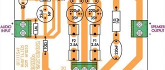
The bias circuit is shown in Figure 4:
Figure 4:
Transformer T1, any step-down transformer 220v/12v with reverse connection. The secondary (step-down) winding is included in the filament circuit of the lamps, and the primary serves as a step-up winding. The output of the rectifier is about -120V and is used to set the bias of the lamps of the final stage of the transmitter.
Useful thing!
The figure above shows a diagram of the field strength indicator. This is a circuit of the simplest detector receiver, only instead of headphones, it has a microammeter, by which we can visually observe the signal level when tuning the transmitter to resonance.
↑ Results
The results were encouraging.
Considering the limitations of our living spaces, and most importantly, the financial means to purchase (or independently manufacture) good acoustics. This unit quite delicately interferes with the musical material and allows you to significantly revive the sound of inexpensive speakers. In the process of listening to various musical genres on different speakers, in different rooms (apartments), with different amplifiers (both tube and transistor) and signal sources, it was possible to achieve a completely comfortable sound of the entire path, select the level of “meatiness” and “sonority”, - may the professionals forgive me, in accordance with their auditory preferences.
To be fair, it must be said that the created device turned out to be, in general, an extra link when working together with a tube SE UMZCH with a power of 2x7 watts on GU-50 lamps, assembled by the author based on the circuit of the respected MAI, loaded on an excellent, but, unfortunately, discontinued DANTAX Opus acoustics.
When turning it on in the specified sound path, it was not necessary to turn the bass and treble adjustment knobs beyond the middle position, since at high volumes there was a danger of economic damage from the alarmingly shuddering dishes in the sideboard, as well as the health of the eardrums of people in the room.
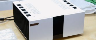
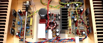
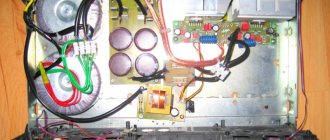
↑ View of the layout
All the insides are visible in the photo:
I don’t think any special comments are needed here. The neutral core is made of 1.5 mm copper wire and is connected to the housing at one point on the rear wall of the block. Power filter capacitors C3, C4, C13 and C14 are mounted directly on the petals of the mounting panels near the lamps. All controls are located outside, at the very bottom there is a power switch, a little higher there is a 4-position flip switch for controlling the switching of reed switches and an input selector indicator, 4 blue indicator LEDs, then separate volume controls and bass and treble controls.
↑ Selection of parts
The design does not contain any super audiophile parts, all resistors are MLT type, designed for the appropriate power, film capacitors, types K73-9, K73-11, K73-17, also for the appropriate voltage.
Electrolytes made in Taiwan are similar to our K50-35 for a voltage of 400 V. You can use almost any transistors in the power supply that match the parameters indicated in the diagram; their choice is not critical. Diodes in the anode supply - any fast 600 V and a current of at least 1 A, and in a filament rectifier - you can use any diode assembly with a current of at least 3 A and a voltage of 50 V. The 0.5 mH inductor is from an old German telephone, you can install any other one or replace it with a resistor of a hundred Ohms (1 watt).
The TAN-1 power transformer was also chosen because it ended up in old storage. It is attached to the middle shelf through a rubber mat and operates quietly, without buzzing.
To eliminate unnecessary vibrations and microphone effects, four rubber feet from an old phone are glued to the bottom of the unit using 3M double-sided automotive tape.