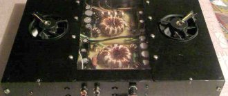
Greetings, friends! Some time ago I was repairing the wonderful Lort 75U-202S amplifier. Before that, it lay in my closet for ten years and finally waited its time. By the way, for my taste, the sound is very good. For example, compared to the legendary Radiotekhnika U-101, I like its sound better. But that’s not about that now. Among other improvements, the input switching unit was replaced in the amplifier, and I decided to write a short article about this experience at the request of workers.
↑ Problems with the native input selector
The input selector on this amplifier is electronic and is made using two four-channel MOS switches KR590KN2. It is precisely this circuit design that causes a number of problems that are inherent, probably, if not in all, then in many electronic switches. Specifically, I had the following: - very strong interpenetration of channels, in which there was no need to talk about high-quality stereo. Switching the “Mono”/”Stereo” modes was practically not felt by ear; — if you connect several signal sources to the amplifier and apply a signal to them, then when you select one input, a signal from another input is mixed into it; — strong interference in the form of background and whistling at some inputs. In addition, the board, together with the selector, contains a phono stage, which also has a number of disadvantages and adds its own part of the interference to the signal. In general, this unit is the bottleneck of the entire amplifier and needs serious improvement.
Switch for four channels
The four input switch is designed for a stereo device. The harmonic coefficient at input voltage up to 1 V does not exceed 0.15%. The load resistance must be at least 47 kOhm.
As can be seen from the diagram, the switch is made on transistor assembly A1, four thyristors (V1, VЗ, V5, V7) and two five-channel switches K190KT1.
Touch contacts E2-E5 are connected to the bases of the transistors of assembly A1. In the initial state, all transistors of this assembly, SCRs and electronic switches of switches A2, AZ are closed, and the LEDs V2, V4, V6, V8 do not light up.
When touch contacts E1 and E2 are touched, the transistor assembly A1, the base of which (pin 11) is connected to contact E2, opens, and the pulse of its collector current causes the thyristor V5 to open.
As a result, LED V6 lights up, a voltage of negative polarity is applied to the gates of the corresponding transistors of microcircuits A2, AZ (pins 7), and they open, connecting the linear output of the receiver to the input of the AF amplifier.
When touching another pair of contacts, the switch operates similarly, while the previously open thyristor closes under the influence of voltages on the plates of capacitors C1-C4 connected to its anode. To reduce the penetration of signals from disconnected program sources to the output of the transistor substrates of microcircuits A2, AZ (pins 5), a positive voltage is applied.
The device provides the ability to switch the AF amplifier to monophonic operating mode. To switch modes, a two-input switch is used. In this case, capacitors C1 and C2, as well as resistor R8, are excluded from it, pin 6 of the A1 chip is connected to the common wire, and pin 7 is connected to pins 11 of the A2 chip, AZ of the input switch. The mono mode is turned on after such changes by touching the sensor contacts E1 and E2.
Rice. 2. Scheme of a four-channel AF signal switch.
When powering the entire device with a voltage of 12 V, the resistance of resistors R6, R7 must be reduced to 1 kOhm; when powered with a voltage of 24 V, the resistance of resistors R2-R5 must be increased to 2 kOhm. The touch contact device is shown in the upper left part of the second diagram. They are made from foil fiberglass.
If there are no microcircuits in the switch, you can use KP304A field-effect transistors, and replace the K198NTZB transistor assembly with KT315B transistors.
Instead of KU101A SCRs, it is permissible to use other SCRs of this series, and instead of AL102B LEDs - any others.
Setting up the switch comes down to selecting resistors R6* - R8*, R12* -R14* to bring the voltages coming to the inputs from different program sources to the same level.
Source: Bornovolokov E.P., Frolov V.V. - Amateur radio circuits.
↑ Chinese selector - for the benefit of humanity
To eliminate these problems, in 90% of cases the simplest solution is chosen: the entire assembly is discarded, and the signal is fed directly to the input of the preamplifier.
At first I was going to do this, because this amplifier was planned to be used with a computer and I did not need more than one input. But fortunately, at that time I had an input switching relay module, 4 channels, RCA, lying idle, purchased from our Chinese friends. Therefore, the concept changed, and it was decided to retain the original functionality in the amplifier. But you won’t be able to simply plug a new module into a ready-made factory design. And, if purely mechanically placing and securing the board in place of the standard selector was not difficult, then it was necessary to think about the electrical alignment.
In the Chinese selector, switching is carried out by simply applying voltage to the coil of the corresponding relay, and switching is implemented using a simple flip-flop switch. In the amplifier, switching is carried out using four buttons on the front panel.
The task was to retain the standard input selection system and somehow combine it with the Chinese module in order to avoid drilling holes in the front panel and installing additional controls in the form of a bib.
CHAPTER 2. Amplifier housing.
I built TDA7293 amplifiers and purchased an input selector 4 years ago. I developed the idea for a case, but basically it was a design made of an aluminum front panel and walls and a top cover made of oak lamellas.
It was an almost classic design, easy to make, but during the suspension of the project I was so tired of this design, I always had the feeling that I had seen this somewhere many times and had already had my fill. Therefore, in view of the recent “disease” with the end cut of plywood, the following design was invented:
The case is made of a set of plywood rectangular rings, a one-piece removable top cover, the base of the case is an aluminum sheet, the front panel is darkened plexiglass. My amplifier will be placed on a low hanging cabinet, so its rear part is clearly visible from above. I don’t really like all this heap of cables on the back of devices, long connectors, so in the back of the case I made a small recess in which the input connectors of the connected cables will be hidden. Of course, not everything will be completely hidden, but at least it will be better.
This should be the final look:
To make the structure, a sheet of 10 mm sanded plywood was purchased. Half of this sheet was also spent on the bookshelf speakers from my other review.
Since the workshop is very small, cutting a whole sheet of plywood on a sawing table is not possible. I first divide the sheet into 2-3 parts with a jigsaw. We cut 10 rectangular sheets of plywood, measuring 400 mm x 300 mm.
We set aside the top and bottom sheets, and mark and cut out windows in the eight central sheets with a jigsaw. The wall thickness of each ring is 10 mm.
Glue the 8 resulting rectangular rings together. press on top and bottom with the remaining sheets and tighten with clamps. I use PVA glue Moment Joiner Super.
In the lower part, the window in the sheet is somewhat different; there it is necessary to provide a shelf to deepen the rear panel, as well as a slightly larger thickness of the side walls, which will later be milled to fit the aluminum base.
In the main part of the body, on the sawing table we saw off the back wall for the rear panel, and glue the main part of the body to the lower part.
To fasten the top cover, I chose black M4 bolts with an internal hex head. I made the recesses in the cover for the bolt head in the same way as for the bookshelf speakers from another review, using a 7 mm wood drill, and then a 4.2 mm drill all the way through.
On the side of the body, we glue plywood cubes to the walls, into which we then place mustache nuts (they will be shown in the photo below). Also in the photo you can already see the walls of the rear niche. I cut them out from a large piece that was left over from the sawn-off back of the body. Glued it on PVA.
Then we take an angle grinder in our hands, with a Velcro attachment and a grinding wheel with 80 grit, draw the radii of curvatures of the case on the top cover, and perpendicular to the plane of the top cover we actively work on creating curves at the corners of the case. We also sand the transitions between layers of plywood sheets on the walls of the case, since mistakes were made during gluing (in the photo above you can see that the parts shifted during gluing, I saw it too late, I don’t know how I missed it), but an angle grinder with such a wheel will correct any mistakes , fortunately there is a large margin in the thickness of the case walls))
By the way, beforehand, after gluing the 8 plywood rings of the body, I also used an angle grinder and a wheel with 80 grit to level the inner walls of the body to an even, smooth state. When working with 80 grit, there are both advantages - the speed of work - and disadvantages - scratches. More about the disadvantages a little later.
Amplifier base.
We saw a sheet of aluminum, 4 mm thick and dimensions 380x280. We apply it to the lower part of the body and draw radii. We grind the radii with an angle grinder / Dremel.
We apply the resulting base and trace with a pencil along the bottom of the body.
We take a router with a groove cutter in our hands and make a 4 mm recess for our base. It didn’t turn out very neatly, there’s nowhere to put the base of the router, all the work is almost suspended, the router tends to cut itself, we need tools to expand the base of the router.
We try on the base, mark, drill and countersink holes for attaching the base to the body
It is necessary to cut a window under the front plexiglass front panel. We print out the window from the drawing on a scale of 1:1, glue it onto a piece of cardboard, cut it out with a scalpel, and glue it to the body with double-sided tape.
We cut out the resulting window with a jigsaw.
Now we need to trim the edges of the window. We also do this with an angle grinder and a circle with 180 grit. Of course, you can do this with a router, but for me it takes longer, and you need good skill, here again there is not enough space for the sole of the router, and there are a lot of straight sections, without a stop I can ruin it. Using an angle grinder, with careful soft movements, we draw straight lines and window radii.
We try on the top cover and use a compass to draw a semicircle of recess for the future volume encoder button.
For the front panel, I considered different options. It should be dark so that the LCD display of the output selector can be seen through it, as well as the control panels of the selector and TV set-top box, but at the same time, the insides of the amplifier should not be visible. There was an option to order a piece of glass and tint it, but the mounting holes had to be very close to the edges, and it seemed that it would be expensive, but honestly I didn’t find out the price. Plexiglas is easier with it, but there are a lot of reviews that it doesn’t work well with the tint film, bubbles appear. I tried the option with tinting varnish, but it is very cloudy, the inscriptions on the LCD display are very cloudy. So I chose another option. Two thin sheets of plexiglass, between them a piece of tint film, this “sandwich” and screwed to the body. During the search for thin plexiglass, I was offered to immediately cut out the parts according to my drawing, since they still cut with a laser cutter, and for 200 rubles. I received these two parts already with holes.
But in fact, as it turned out, I received the parts not from plexiglass (acrylic), but from transparent PET 2 mm thick.
I received a piece of film from an auto-tinting company as a gift, with a light transmittance of 30%; this turned out to be optimal for a bright image of the output selector screen and hiding the insides of the amplifier.
Since PET is not particularly afraid of the tint film, I simply glued it to one of the parts and covered the second one on top. I placed a few drops of superglue on top at several points so that the resulting glass would not peel off and dust would not get in there.
When fitting the transparent panel to the body, a small problem was identified. The top cover of the case turned out to be slightly curved, it is not visible to the eye, but there is a hump of 1-1.5 mm upwards. Because of this, the upper extreme points of the panel rested against the housing cover, and in the middle there was a gap between the panel and the housing cover. You cannot buy flat plywood from us. There were two solutions: 1. Sand the front panel under the top cover. But PET is a bit viscous material, I was generally afraid of ruining the finished parts. 2. Make a groove in the top cover. I thought that this option was better, simpler, and as a plus I would fix the panel in the upper part, in a groove, relative to the body. You need to make a groove with a router, the groove is only 4 mm, I have a milling attachment for Dremel, but I had to go find it and get it from the closet, unfasten the flexible shaft, put on the Dremel, and screw on the inconvenient bottom nut. I decided that there was too much work for a simple shallow hidden groove and decided to do it by hand like this:
A thin cutter into a flexible shaft, two steel rulers as a limiter for the cutter’s stroke, and with “muscular” control of the depth of entry of the cutter, we quickly make a groove. Problem solved.
Next we move on to the volume encoder knob. I ordered this pen: 4pcs aluminum plastic knob potentiometer knob 48*19mm potentiometer cap Volume knob switch cap Encoder for amplifier. Diameter - 48 mm.
The diameter of the recess for the handle in the body is 50 mm in diameter and 7 mm in depth. We fasten the housing with the top cover to the table with clamps, place the router and make a recess for the encoder handle and try on the handle.
I took the following power button: [1 pc. Colorful Useful Durable 22mm LED Power Push Button Switch Momentary/Latching Waterproof Metal Self Locking Stainless Buy on AliExpress] Thread diameter is 22mm. The button has a high pressure part; when pressed, the finger does not fall further than the front surface of the button. The hole in the body was made with a step drill.
Next, we take a grinder, grinding wheels with 220 grit, and diligently sand the body. We even grind very diligently, because, as it turned out, it is necessary to remove all the defects from the work of the grinding wheel with 80 grit.
In the photo below you can see the body prepared for oil coating. This is already the second attempt, the first one was unsuccessful, the oil “revealed” all the transverse deep scratches from the coarse grain, they are just not visible on the cut of the plywood. I had to remove the oil and polish it more thoroughly.
After final sanding, coat the body with oil. As the first layer I used BIOFA tinting oil. Dark brown color, apply in a thin layer so as not to lose the texture.
Cover the second layer with BELINKA INTERIER oil. It will give the body a golden hue, as well as a pleasant shine, like oil with wax. Apply this oil in two layers, removing excess.
Next, polish the body with a wool wheel.
We fasten the front panel from the inside of the case with small self-tapping screws.
The hole for the encoder shaft was made with a 7mm drill. On the reverse side, the encoder housing is pressed against the front panel. We install the encoder knob and the power button.
The body is ready!
↑ Modernization of the standard input switch
For simplicity, it was decided to use standard circuitry as much as possible. Let's look at the diagram of a standard switch.
The switch is assembled on a K155TM5 chip, which consists of four D-flip-flops in one DIP14 package.
When any of the SB1-SB4 buttons is closed, a signal is sent to the corresponding input, which causes the trigger to switch and a high level voltage to appear at the output. Next, according to the standard circuit, the control voltage from one of the outputs is supplied to one of the logical inputs of the KR590KN2, which in turn switches the selected input of the amplifier. The modification consists in using the KR590KN2 microcircuit to switch not the signal, but the 12V voltage to power the selector relay. However, KR590KN2 cannot be used for this purpose, since it allows switching voltages from –10V to +10V. For our purpose, we change the chip to KR590KN5, which allows switching voltages from –15V to +15V.
The modified diagram looks like this:
Details and connection
The K561KP1 microcircuit can switch both digital and analog signals. But, when switching an analog signal, it is necessary that it be between the power poles, preferably in the middle (this will result in minimal distortion of the audio signal).
Therefore, the second pin of the minus power supply of the keys (pin 7), which is usually connected to the common minus of the power supply, is here connected to a negative power supply (-5V). Thus, the switch's power supply is bipolar.
There are no problems with this, since preliminary ULFs are usually made using op-amp circuits, also powered from a bipolar source. If the source voltage is more than ±7V, you need to supply power to the circuit through step-down stabilizers, for example, make the source +5V on the 7805 integrated stabilizer, and make the negative source on the idle parametric stabilizer from a 4.7-5.6V zener diode and a resistor. LEDs HL1-HL3 - any indicator, for example, AL307 or their analogues.
↑ Implementation in hardware
To compactly accommodate additional elements, a small printed circuit board was developed.
It is placed “second floor” on the standard printed circuit board of the switch on racks of a suitable height
In this case, spots 3, 4, 5, 6 of the standard switch are electrically connected to spots 3*, 4*, 5*, 6* of the additional board using cut-off element leads or inter-board connectors.
It remains to connect the power circuits to all consumers. What to get from where and where to connect is shown in the table:
We connect socket XS1 of the additional switch board with a cable to the corresponding connector of the Chinese selector. We connect the signal output of the selector with a shielded (microphone) cable to the inputs of the preamplifier.
On the rear panel of the amplifier, cut a hole of the required size to accommodate the connectors of the new selector and attach it to the chassis.
KOMITART - entertainment and educational portal
Sections of the site
- " To home
- » Radio amateur
- » APEX AUDIO
- " Power supplies
- » Guitar accessories
- » Do it yourself
- » For motorists
- » Service-Manual
- » PREAMPLIFIERS
- » Free programs
- " Computer
- » Books
- " Women things
- We cook deliciously and quickly
- » Games on the site
- " Humor
- » Miscellaneous - interesting
