electronic two-channel tone control of high and low sound frequencies
The microcircuit is an electronic two-channel tone control for higher and lower audio frequencies. Designed for use in sound reproducing and receiving and amplifying equipment of the 1st and 2nd classes together with K174UN12. The microcircuits include voltage-controlled amplifiers and voltage converters. Analogue of the TCA740
.
Contains 204
integral elements.
Structurally designed in a housing type 238.16-2
.
Weight no more than 1.5 g
.
Microcircuits for household radio equipment
: Directory /I. V. Novachek, V. M. Petukhov, I. P. Bludov, A. V. Yurovsky. - Moscow: KUBK-a, 1995. — 384 pp.: ill.
Integrated circuits and their foreign analogues
: Directory. Volume 2./A. V. Nefedov. - M.: KUBK-a, 1996. — 640 pp.: ill.
Analog integrated circuits
: Directory / A.L. Bulychev, V. I. Galkin, V. A. Prokhorenko. - 2nd edition, revised and expanded - Minsk: Belarus, 1993. — 382s.
| 1 | Rated supply voltage | 15 V |
| 2 | Current consumption at Up = 15 V typical value | 40 mA 34 mA |
| 3 | Operating frequency range at level -1 dB at Up = 15 V, | 20…20,000 Hz |
| 4 | The depth of adjustment of the gain of lower audio frequencies (40 Hz) at Up = 15 V, Uin = 1 V is not less than the typical value | ± 15 dB ± 16 dB |
| 5 | The depth of gain adjustment for higher audio frequencies (16 kHz) at Up = 15 V, Uin = 1 V is not less than the typical value | ± 15 dB ± 16 dB |
| 6 | Change in the controller gain at a frequency of 1 kHz when the control voltage on pins 4 and 12 changes from 1 to 10 V, Up = 15 V, Uin = 1 V no more than typical value | ± 2 dB ± 1.5 dB |
| 7 | Harmonic coefficient at Up = 15 V, Uout = 1 V : K174UN10A no more than typical value K174UN10B no more than typical value | 0,2 %0,1 %0,5 %0,3 % |
| 8 | Input and output voltage at Up = 15 V, Kg 0.7% : K174UN10A no more than typical value K174UN10B no more than typical value | 1.6 V 2.0 V 1.2 V 1.5 V |
| 9 | Output signal-to-noise ratio at Uout = 50 mV, Up = 15 V, : K174UN10A no less K174UN10B no less | 66 dB 60 dB |
| 10 | Transition attenuation between channels at Uout = 1 V, Up = 15 V, : at f = 250 Hz...12.5 kHz , no less than typical value at f = 20 Hz...20 kHz , no less than typical value | 56 dB 60 dB 46 dB 50 dB |
| 11 | Control voltage at pins 4 and 12 at Up = 15 V | 1…10 V |
| 12 | Input current at control terminals at Upr = 15 V, Ucontrol = 8 V | 25 µA |
| 13 | Input resistance of the regulator is not less than | 15 kOhm |
www.qrz.ru
K174UN10A, K174UN10B | Techniques and Programs
October 7, 2011 by admin Comment »
Two-channel amplifiers with electronic frequency response control. Designed for use as tone controls for high and low frequencies of sound reproducing and receiving and amplifying equipment of the first and second classes. The microcircuits are structurally designed in a housing type 238.16-2.
Rice. 145. Typical connection diagram for IC K174UN10 U - voltage converters, 2 - voltage controlled amplifiers) |
Signal-to-noise ratio: 66 dB for K174UN10A and 60 dB for K174UN10B. The depth of tone control at frequencies of 40 Hz and 16 kHz is at least +15 dB. Changing the controller transmission coefficient when changing the control voltage at the terminals 4
and
12
from 1 to 10 V and a frequency of 1 kHz - no more than +2 dB.
The maximum constant control voltage at pins
4
and
12 is
no more than 12 V;
the highest signal voltage value at pins /, 2, 6,
7,
9, 10, 14 and 15
is above 1 V (rms).
1 For K174UN10B with UBUK
= 0.45 V; for K174UN10A K g <0.2%.
2 At Ku c = 1 and frequencies of 1 and 12.5 kHz.
Note. The parameter values are given at a nominal power supply voltage of 15 V and a frequency of 1 kHz.
nauchebe.net
Functional purpose
K174AF1TBA920, TAA700 Line scan generator K174AF2TBA940 Line scan generator K174AF4TBA530, MDA530, A231D RGBK174AF5TDA2530 matrix RGBK174GL1TDA1170 vertical scan circuit K174GL1 ATDA1270 Vertical scanning circuit K174GL2TEA1020 Vertical scanning circuit K174GL2ATEA1120, TEA1020 Vertical scanning circuit K174GF2XR-2206 special form Signal generator K174KN1SAS560, SAS570, KB1106KT1 Switching selector channels K174KN2SAS580 Channel switching selector K174KP1TDA1029 Analog switch 2x4K174PS1S042P, UL1042NDouble balanced mixer K174PS2S042PDouble balanced mixer K174PS3S042PDouble balanced mixer K174PS4S042PDouble balanced mixer K174 UV1SL550Adjustable UVChK174UV2SL1030Wideband amplifierK174UV4SA3028Wideband UVChK174UV5NE592Wideband video amplifierK174UK1TSA660Dimmer controlK174UN3TAA310PreamplifierK174UN4TAA300, A211D, TBA915UNCH (1 W)K174UN5TAA900UNCh (2 W)K174UN7TBA810, A 205K,D, A210K,DUL1481PT, ULA6481UNCH (4.5 W)K174UN8TAA310UNCH (2 W)K174UN9TSA940, TSA940E, UL1440TUnch (5 W)K174UN10TSA740, A274DRegulator two-channel timbre K174UN11TDA2020, TDA2010, MDA2020, MDA2010ULF (12 W)K174UN12TSA730, A273Dtwo-channel volume controlK174UN13TDA1002, A202Drecording/playback amplifierK174UN14TDA2003, UL1413 G, CA2002, CA2004, LM383, TDA2002ULF (5.5 W)K174UN15TDA2004, TDA2005Stereo ULF (6 W)K174UN17TA7688P, TA7688FULCH for stereo phonesK174UN18AN7145MStereo ULF (2 W)K174UN19TDA2030H,V, A2030H,V,TDA2040ULF (15 W)K174UN21TDA1050Low-voltage stereo UNCHK174UN23TDA7050Low-voltage stereo UNCHK174U N24TDA7052Stereo ULF (2x0.6 W)K174UN25TDA2004Stereo ULF (6 W)K174UN26TDA7050Two-channel ULF (150 mW)K174UN27TDA2005UNCHK174UP1TVA510, TVA970, A270D Signal amplifier brightness K174UP2TL441Logarithmic amplifier K174UR1TBA120S, A220DUPCHZK174UR2TVA440, A240DUPCHIK174UR3TVA120, K526UR1ChM radio channel path K174UR4TVA120U, A223DUPCHZK174UR5TDA2541, A241DUPCHIK174UR6TVA120TU PCHIK174UR7TSA770, MSA770AEconomic UPCHZK174UR8TDA2546UPCH, second PCHK174UR10SL1430, TDA1236Preliminary UPCHK174UR11TDA1236UPChZ with output to VMK174UR12TDA4420, TDA2549UPCHIK174ХА1T BA2591, TCA660, TBA510Chroma demodulator SECAMK174XA2TSA440, UL1203N, A244DUPCH AM with ARUC174XA3NE545ENoise suppressor K174XA3ALM1011AN, NT646Noise suppressor K174XA3BLM1111AN, NE646Noise suppressor K174ХА4NE561 PLL circuit 174ХА5TDA1047 FM radio receiver path K174ХА6TDA1047, A225D Path FM radio receiver K174XA8TSA650, MSA650 Color subcarrier demodulator K174XA9TSA640, MSA640 Chroma signal processing circuit K174XA10TDA1083, A283D, KA22424, TA8613, TDA4100 AM-FM radio receiver path K174XA11TDA25 93, TDA2591, A291D, A255D Synchronization processor K174ХА12NE561 PLL circuit 174ХА14TDA4500, A290D, UL1621N Stereo decoder K174ХА15TDA1062 FM radio receiver path K174ХА16TDA3520, MDA3520, A3 520D SECAMK174XA17TDA3501, MDA3501, A3501D, UL1621N color decoderK174XA18XR- video processor 215 PLL circuit 174ХА19TDA1093B Tuning voltage generator UKVK174ХА20TUA2000-2 Mixer and local oscillator of the TV receiver K174ХА24TDA2595 Synchronization processor K174ХА25TDA4100, TDA4610 Geometric distortion corrector K174ХА26МS3361 Frequency converter, IF and CHDK174ХА27TDA4565, MDA4565, A4565D, UL1295, TDA4570 Color corrector K174ХА28TDA3510, MDA3510, A3510D, KXA039 Color decoder PALК174ХА31TDA3530, MDA3530, XA05 5Chromatic decoder SECAMК174ХА32TDA4555, MDA4555, A4555D, UL1285 , TDA4570 Decoder PAL/SECAM/NTSCК174ХА33TDA4680, A3505D, TDA3505, MDA3505, UL1275 Video processor module, color K174ХА34TDA2071, УА06ХА1, TDA7021, TDA7010, K174ХА4201 FM path radio receiver K174ХА36TEA5570 AM radio receiver path and UNCHK174ХА38TDA8305A, KR1039ХА2 Low-signal TV receiver path K174ХА39TDA4502 Small-signal TV receiver path K174ХА41TDA3810 Mono/stereo switch K174ХА42TDA70 00FM radio receiver path K174XA4201TDA7010FM radio receiver path K174XA46TEA5592FM radio path -AM Hi-Fi radioK174UN10A - ULF - MICROCIRCUITS - Electronic components (catalog)
| Housing: DIP-16 Main parameters of m/s K174UN10A: | |
| Consumption current | <40mA |
| Frequency range -1dB level | 20Hz..20KHz |
| Depth of adjustment of low frequencies (40Hz), not less | ±15dB |
| Low frequency adjustment depth (16KHz), no less | ±15dB |
| Maximum permissible voltage on pins 4 and 12 | 12V |
| Maximum input voltage | 2B |
| Minimum load resistance | 5Kom |
| Harmonic coefficient, no more | 0,2% |
| Signal-to-noise ratio (Uout=50mV), no more | 66dB |
| Input impedance (f=1KHz) | 15Kom |
| Ambient temperature | -10..+55°С |
Purpose of pins m/s K174UN10A:
| 3 | Voltage Controlled Amplifier I Output |
| 4 | Control of amplifiers I and II |
| 5 | Voltage Controlled Amplifier II Output |
| 6,7 | Voltage Controlled Amplifier II Inputs |
| 8 | + Nutrition |
| 9,10 | Voltage Controlled Amplifier III Inputs |
| 11 | Voltage Controlled Amplifier III Output |
| 12 | Controlling Voltage Controlled Amplifiers III and IV |
| 13 | Voltage Controlled Amplifier IV Output |
| 14,15 | Voltage Controlled Amplifier IV Input |
| 16 | General conclusion |
tec.org.ru
DataSheet
| Block diagram of IC K174UN10 (A, B) | Typical circuit diagram for connecting IC K174UN10 (A, B) as a two-channel tone control |
| Functional composition: I, II, IV, V - voltage-controlled amplifiers; III, VI - voltage converters | Typical circuit diagram for switching on the K174UN10 microcircuit (A, B) |
| Schematic diagram of a preamplifier-corrector with electronic volume, tone and channel balance controls | Housing type 238.16-2 |
Description
The microcircuits are a two-channel tone control for use in high-quality sound reproduction equipment. Main functional purpose: two-channel amplifier with electronic frequency response control. Contains 204 integral elements. Housing type 238.16-2, weight no more than 2.5 g. Functional composition: U1 - U4 - inverting operational amplifiers: K1, K2 - control stages.
Pin assignment: 1 - input 2 of amplifier U3; 2 - input 1 of amplifier U3; 3 - output of amplifier U3; 4 — bass control; 5 - output of amplifier U4; 6 - input 1 of amplifier U4; 7 - input 2 of amplifier U4; 8 — supply voltage (+Up); 9 - input 2 of amplifier U2; 10 - input 1 of amplifier U2; 11 - output of amplifier U2; 12 — HF control; 13 - output of amplifier U1; 14 - input 1 of amplifier U1; 15 — input 2 of amplifier U1; 16 - general.
| Electrical parameters | ||||
| Options | Conditions | K174UN10A | K174UN10B | Unit change |
| Analogue | — | TCA740 | TCA740 | — |
| Input voltage at pins 3, 5, 11, 13 | U1 | 0,35…0,6 | 0,35…0,6 | IN |
| U2 | 0,7…1,2 | 0,7…1,2 | ||
| Noise voltage at the output of each channel | — | ≤50 | ≤100 | µV |
| Consumption current | — | 5…40 | 5…40 | mA |
| Voltage gain of each channel | — | 15…20 | 15…20 | dB |
| Voltage attenuation coefficient of each channel | — | -20…-15 | -20…-15 | dB |
| Harmonic distortion of each channel | — | ≤0,2 | ≤0,5 | % |
| Input voltage attenuation ratio between channels | — | ≥56 | ≥56 | dB |
| Bandwidth | — | 20 Hz…20 kHz | 20 Hz…20 kHz | — |
| Input impedance in a typical connection circuit | — | ≥15 | ≥15 | kOhm |
| Transmission coefficient in a typical switching circuit | at a frequency of 1 kHz when changing U4 and U12 from 1 to 10 V | 0±2 | 0±2 | dB |
| Maximum permissible operating conditions | ||||
| Options | Conditions | K174UN10A | K174UN10B | Unit. |
| Supply voltage | — | 13,5…16,5 | 13,5…16,5 | IN |
| Voltage at pins 4 and 12 | — | 10 | 10 | IN |
| Voltage at pins 11, 2, 6, 7, 9, 10, 14, 15 | — | 0…1 | 0…1 | IN |
| Permissible value of static potential | — | 200 | 200 | IN |
| Load resistance of each channel | — | ≥5 | ≥5 | kOhm |
| Ambient temperature | — | -10…+55 | -10…+55 | °C |
| Amplitude-frequency characteristics at Up = 15 V, Uout 1 kG = 1 V and various values of control voltage at pins 4 and 12 | Regulating characteristics of controlled amplifiers I and II at Up = 15 V, f = 40 kHz |
| Regulating characteristics of controlled amplifiers III and IV at Up = 15 V, f = 16 kHz | Dependence of current consumption on ambient temperature at Up = 15 V. The area of spread of parameter values for 95% of microcircuits is shaded |
| The dependence of the harmonic coefficient on the output voltage is a solid line (at Up = 15 V, f = 3 kHz); dotted line (at Up = 15 V, f = 40 Hz...16 kHz) | Dependence of current consumption on supply voltage at T = +25 °C. The area of dispersion of parameter values for 95% of microcircuits is shaded |
If you find an error, please select a piece of text and press Ctrl+Enter.
K174UN10 - Reference book on microcircuits
Purpose, connection diagram, parameters
Category
Domestic microcircuits
The K174UN10 microcircuit is an electronic two-channel tone control for higher and lower audio frequencies. Designed for use in sound reproducing and receiving and amplifying equipment of the 1st and 2nd classes together with K174UN12.
The microcircuits include voltage-controlled amplifiers and voltage converters. Analogue of the TCA740 chip. Contains 204 integral elements. Structurally designed in a DIP-16 housing. Weight no more than 1.5 g, appearance is shown in the figure
Pin assignment
1,2 - amplifier input UI; 3 - amplifier output UI; 4 - control of amplifiers УI and УII; 5 - output of amplifier UII; 6.7 - input of amplifier UII; 8 — power supply + Ui.p.; 9,10 - input of amplifier UIII; 11 - output of amplifier UIII; 12 — control of amplifiers UIII and UIV; 13 - output of amplifier UIV; 14.15 - amplifier input УIV;
16 - general (-Ui.p.).
Structural (internal) diagram
Connection diagram
Electrical parameters
| ═ 1 ═ | ═ Rated supply voltage | ═ 15 V |
| ═ 2 ═ ═ | ═ Current consumption at Up = 15 V ═ typical value | ═ 40 mA ═ 34 mA |
| ═ 3 ═ | ═ Operating frequency range at level -1 dB at Up = 15 V, | ═ 20┘20 000 Hz |
| ═ 4 ═ ═ ═ | ═ Depth of adjustment of the gain of lower audio frequencies (40 Hz) ═ at Up = 15 V, Uin = 1 V not less than ═ typical value | ═ ═ ± 15 dB ═ ± 16 dB |
| ═ 5 ═ ═ ═ | ═ Depth of gain adjustment for higher audio frequencies (16 kHz) ═ at Up = 15 V, Uin = 1 V not less than ═ typical value | ═ ═ ± 15 dB ═ ± 16 dB |
| ═ 6 ═ ═ ═ ═ | ═ Changing the controller gain at a frequency of 1 kHz ═ when changing the control voltage at pins 4 and 12 ═ from 1 to 10 V, Up = 15 V, Uin = 1 V no more than ═ typical value | ═ ═ ═ ± 2 dB ═ ± 1.5 dB |
| ═ 7 ═ ═ ═ ═ ═ | ═ Harmonic coefficient at Up = 15 V, Uout = 1 V: ═ K174UN10A no more than ═ typical value ═ K174UN10B no more than ═ typical value | ═ ═ 0,2 % ═ 0,1 % ═ 0,5 % ═ 0,3 % |
| ═ 8 ═ ═ ═ ═ ═ | ═ Input and output voltage at Up = 15 V, Kg 0.7%: ═ K174UN10A no more than ═ typical value ═ K174UN10B no more than ═ typical value | ═ ═ 1.6 V ═ 2.0 V ═ 1.2 V ═ 1.5 V |
| ═ 9 ═ ═ ═ | ═ Signal-to-noise ratio at the output at Uout = 50 mV, Up = 15 V: ═ K174UN10A no less ═ K174UN10B no less | ═ ═ 66 dB ═ 60 dB |
| 10 ═ ═ ═ ═ ═ | ═ Transition attenuation between channels at Uout = 1 V, Up = 15 V,: ═ at f = 250 Hz┘12.5 kHz, no less than ═ typical value ═ at f = 20 Hz┘20 kHz, no less than ═ typical value | ═ ═ 56 dB ═ 60 dB ═ 46 dB ═ 50 dB |
| 11 ═ | ═ Control voltage at pins 4 and 12 at Up = 15 V | ═ 1┘10 V |
| 12 ═ | ═ Input current at control terminals at Up = 15 V, Ucontrol = 8 V | ═ 25 µA |
| 13 ═ | ═ Input resistance of the regulator is not less than | ═ 15 kOhm |
Maximum permissible operating conditions
| ═ 1 ═ | ═ Supply voltage | ═ 13.5┘16.5 V |
| ═ 2 ═ | ═ Maximum constant control voltage | ═ 12 V |
| ═ 3 ═ | ═ Maximum input voltage | ═ 2 V |
| ═ 4 ═ | ═ Minimum load resistance | ═ 5 kOhm |
| ═ 5 ═ ═ | ═ Maximum static potential ═ at the terminals of the microcircuit | ═ 30 V ═ |
| ═ 6 ═ | ═ Ambient temperature | ═ -10┘+55°С |
Literature
Microcircuits for household radio equipment: Directory /I. V. Novachek, V. M. Petukhov, I. P. Bludov, A. V. Yurovsky. - Moscow: KUBK-a, 1995. — 384 pp.: ill.
Integrated circuits and their foreign analogues: Directory. Volume 2./A. V. Nefedov. - M.: KUBK-a, 1996. — 640 pp.: ill.
Analog integrated circuits: Directory / A.L. Bulychev, V. I. Galkin, V. A. Prokhorenko. - 2nd edition, revised and expanded - Minsk: Belarus, 1993. — 382s.
radio-uchebnik.ru
K174un10a connection diagram
The K series of microcircuits, designed for operation in various paths of household monophonic and stereophonic radio equipment (TVs, radios, tape recorders), has been replenished with five new microcircuits: KUN10 - two-channel amplifier with electronic adjustment of the frequency response; tone control;. About the amplifier with electronic control of equal gain and balance between channels; volume control and stereo balance;. The microcircuits are made using planar epitaxial technology with elements isolated by a p-junction.
Search data for your request:
Schemes, reference books, datasheets:
Price lists, prices:
Discussions, articles, manuals:
Wait for the search to complete in all databases. Upon completion, a link will appear to access the found materials.
WATCH THE VIDEO ON THE TOPIC: AC/DC – Thunderstruck (Official Video)
Amplifier K174UN10
Pages 1 2 Forward. In terms of sound? In particular, noise, distortion, etc. I’m talking specifically about these, and not some other microcircuits, due to the fact that I have these particular ones, it is not possible to purchase something now for a number of reasons.
The remaining nodes on KUD2, this is all to make it clear approximately the class of the device, so as not to go to extremes, such as Hi-End or, on the contrary, a “children’s brinchalka”. They say that it is noisy, but in articles they write about db and even about ! Maybe it makes noise for those who use UMZCH with very high sensitivity? Well, that’s the feeling I got from the reviews. Personally, I most likely won’t do any noise reduction, so there’s no point in chasing CD-like noise.
Well, the question is, is KUN10 better or worse for this purpose? Maybe someone can share purely scientific justifications for the pros and cons of the above-mentioned microcircuits? Without subjective types, this is G. It’s just how they usually write it, not scientifically, somehow KUN10 is also attractive because it actually has four regulators, with two, one per pair of adjustment inputs, according to an analog multiplier circuit!
But I didn’t find out what principle it was made on, but it cannot be adjusted separately by channel level, there is a general level and balance, but I would prefer it separately by channel. There is also an idea to make it on KPA1, I have a couple, but there will be too many details, since I will control it through KIE11, with all the accompanying ones. I would still like to use analog ones. The issue is not so much noise as audible distortion.
Specific percentages are a spherical horse in a vacuum. It's not percentages that sound, but specific circuitry. The shock wave should be on the input bipolar according to the Sukhov scheme modified by Polishchuk or on a pair of bipolars of different structures according to the Galakhov scheme:.
All sorts of UL microcircuits are a waste. The difference in sound is striking, the complexity and cost of parts are the same. A sendust 3D GSP head is needed - on HP2. Making a tape recorder without SDP is stupid. The easiest way to make SDP-2 is in the classic version. There are a minimum of complications, but the writing will be incomparably better. But it is done once and is worth it. Now all this is much easier than in years because everyone has a free spectrum analyzer on their sound system and PC.
It is better to make the necessary switchings with miniature relays with gold-plated contacts. Any assemblies with field-effect transistors are a waste of time. Sasha, thank you, of course, for the recommendations, but you didn’t write a word on the question itself, I asked about AD or KUN10, and you wrote about a lot of things, just not about what I asked.
Of course, we can develop the topic a little according to your recommendations, but I think not here, and not now. Whereas in the schemes I described it will be in the region of hundredths - thousandths. Why use UV for portable cassette players in the first place? Regarding the UV, I will think about what you wrote. But what is the point of building a path with hundredths of harmonics if the tape does not provide this?
Is this possible? I was just trying to do Polishhukovsky, you yourself gave a link to the topic, then I stumbled over an incorrect low-frequency correction and abandoned it. Maybe I’ll return to this issue. By the way, is Lukin still in business? I think he was on the editorial board of Radiohobby magazine? A strange question for a person who has been on the forum for a year PS: Have you tried using the search? They say it helps. Ahh, it was not in vain that I decided to ask, since the site found him a long time ago. I remembered that several years ago I came across a message here that one of the “elders” of circuit design had died.
That's him. It didn’t occur to me to search for such a question here. Okay, then let's go back to my first post in this thread. Is there anyone else here who can tell you something about this topic? What can I say? It is not clear from the question, for what purpose is a tape recorder made?
If it just works and keeps your hands busy, then any of the Ministry of Agriculture will do. It is also unclear, if MSK is available, then why not just prototype both, and, armed with a spectrolab or ears, determine which is better.
Cassette recording is long dead. All the developments are posted on the Internet, the diagrams are chewed. Look through old threads, at least here.
Atom theme feed. Radiohobby Forum Internet conference of the Radiohobby magazine. You are not logged in. Topics: Active No reply. When registering, do not use email in the Yandex and Mail domains. The letter will not physically reach them from servers in Ukraine, due to sanctions imposed by the Ukrainian government against these companies. Anyone who has previously used such mail is recommended to change it in order to maintain the same functionality of the forum.
We kindly ask you to attach pictures and files directly to messages so that they physically remain on the forum website! The "Downloads" link is located at the bottom right of the message typing form. Subscription to Radiohobby magazine has been discontinued. The forum continues its work. Download the conference archive Go to the journal's home page. I haven’t decided yet about SHG. Offline. UZ - UD2 3. They cost pennies. But they give a predictable good sound. Do the noise reduction according to Polishchuk. The changes are minimal, and it sounds much better.
The indicator is a native one from Mayak or some kind of LED. Regarding further amplification, it is better to make it external, i.e. Re: Which is better for the recording channel of a tape recorder, AD or KUN10 Sasha, thanks, of course, for the recommendations, but you didn’t write a word on the question itself, I asked about AD or KUN10, and you They wrote about a lot of things, but not about what I asked.
Regarding my actual questions from the first message, any thoughts? Re: Which is better for the recording channel of a tape recorder, AD or KUN10 Evgeniy writes: what is the point of building a path with hundredths of harmonics if the tape does not give this. Edited by AlexMax There are currently 0 users in this topic, 1 guests [Bot] Googlebot. Forum footer Go Questions about subscription and delivery. English Russian.
Chip K174UN10A
Login to the site Register. To learn more. Gifted - A gift to many. Spacebrother Boards for various devices for modifications to audio and household appliances.
Kun10 switching diagram. Links to Important Stuff. How to assemble a file from parts · Quotes from the book Fahrenheit · Download complex ones.
Popular Amateur Radio Handbook.pdf
The microcircuit is an electronic two-channel tone control for higher and lower audio frequencies. Designed for use in sound-reproducing and receiving-amplifier equipment of the 1st and 2nd classes together with KUN. The microcircuits include voltage-controlled amplifiers and voltage converters. Analogue of TCA microcircuit Contains integrated elements. Structurally designed in a housing type Weight no more than 1.5 g. Novacek, V.
K174UN10 scheme
A two-channel audio frequency preamplifier with finely compensated electronic volume and tone control for low and high frequencies can be built on specialized low-noise K-series microcircuits. The simple device that will be discussed in this article is intended for the modernization of stationary industrial equipment. 2nd The use of electronic adjustments allows you to eliminate passing the signal through variable resistors, thereby eliminating their inherent noise, rustling and distortion that occurs when the current-collecting contact is not in good enough contact with the resistive layer. In addition, the control circuits become insensitive to background noise at a mains frequency of 50 Hz, which allows you to place variable resistors in any convenient location of the device.
Judgment Day :.
Modlabs.net forums: How to make a fanbus with button control? — Modlabs.net forums
Back 1 2 3 Forward. What is the most convenient way to solder? Soldering iron W. Scheme of a car radio on a KUL1 microcircuit. The result was a device with the following characteristics: 1.
K174UN10A, K174UN10B - two-channel tone control
KRVI microcircuit KRVI1 microcircuit in ultra-stable timer mode KRPM microcircuit Popular reference book for radio amateurs. Features of the sensor KRPP microcircuit KUD microcircuit
The preliminary ultrasonic circuit on chips of the K series timbre is built on a DA2 chip of the KUN10A type (imported analogue - TSA).
Forum for lovers of reel-to-reel tape recorders, analog video and audio equipment
We accept cards for payment. Price list Excel. Helpful information.
K174Un10A connection circuit – K174UN10A, K174UN10B – two-channel tone control – DataSheet
Moderators: cooper, Georgk2, Siola. This forum is currently being viewed by: Google [Bot] and guests: 1. Forum for lovers of reel-to-reel tape recorders, analog video and audio equipment. Good analog, high-quality equipment is necessary for those who have been searching for their own sound for a long time and unsuccessfully; it is necessary for those who have already realized that digital the sound will always be missing something Previous visit: Sat Oct 12, pm Current time: Sat Oct 12, pm. Added: Mon Feb 02, pm.
By connecting pins 7 and 12, 8 and 11 with jumpers or using external resistors instead, you can change the gain Ki. As Ki increases, the passband narrows proportionally and the common-mode signal attenuation coefficient decreases.
An unusual use of a long-forgotten microcircuit.
This page is hosted for free by zzz. Do you want to support owner of this site? Click here and donate to his account some amount, he will be able to use it to pay for any of our services, including removing this ad. Firmware for microcontrollers download Selection of capacitors for the electric motor and their connection Do-it-yourself video transmitter from dandy Light up the LED from one battery Telescopic antenna for the fm receiver buy in St. Petersburg TV electron 51ts di circuit Relay RES 6 characteristics rs Wiring diagram for the Panasonic cq-cne radio tape recorder Ren 18 relay contents precious metals Volume control on the kha17 chip Domestic operational amplifiers with unipolar power supply. Microcircuit kun10 switching circuit They sent their gathering guests, I rummaged around, I doubted that the car was crawling with its nose towards the center of the planet. Varent greeted remains
Preliminary ultrasonic frequency on K174 series microcircuits
View series K The microcircuits are a two-channel tone control for use in high-quality sound reproduction equipment. Main functional purpose: two-channel amplifier with electronic frequency response control. Contain integral elements.
all-audio.pro
Two-channel tone control on K174UN10
September 5, 2012 by admin Comment »
The microcircuit is an electronic two-channel tone control for higher and lower audio frequencies. Designed for use in sound reproducing and receiving and amplifying equipment of the 1st and 2nd classes together with K174UN12. The microcircuits include voltage-controlled amplifiers and voltage converters. Analogue of the TCA740 chip. Contains 204 integral elements. Structurally designed in a housing type 238.16-2. Weight no more than 1.5 g.
IC housing K174UN10
1,2 – amplifier input UI; 3 – output of amplifier UI; 4 – control of amplifiers УI and УII; 5 – output of amplifier UII; 6,7 – input of amplifier UII; 8 – power supply + Ui.p.; 9,10 – input of amplifier UIII; 11 – output of amplifier UIII; 12 – control of amplifiers UIII and UIV; 13 – output of amplifier УIV; 14.15 – amplifier input УIV; 16 – general (-Ui.p.).
Functional diagram of IC K174UN4
Normal Functional composition: УI, УII, УIII, УIV – voltage-controlled amplifiers; KI,KII – voltage converters
Typical connection diagram for IC K174UN10
Electrical parameters
| 1 | Rated supply voltage | 15 V |
| 2 | Current consumption at Up = 15 V typical value | 40 mA 34 mA |
| 3 | Operating frequency range at level -1 dB at Up = 15 V, | 20…20,000 Hz |
| 4 | The depth of adjustment of the gain of lower audio frequencies (40 Hz) at Up = 15 V, Uin = 1 V is not less than the typical value | ± 15 dB ± 16 dB |
| 5 | The depth of gain adjustment for higher audio frequencies (16 kHz) at Up = 15 V, Uin = 1 V is not less than the typical value | ± 15 dB ± 16 dB |
| 6 | Change in the controller gain at a frequency of 1 kHz when the control voltage on pins 4 and 12 changes from 1 to 10 V, Up = 15 V, Uin = 1 V no more than typical value | ± 2 dB ± 1.5 dB |
| 7 | Harmonic coefficient at Up = 15 V, Uout = 1 V: K174UN10A no more than typical value K174UN10B no more than typical value | 0,2 % 0,1 % 0,5 % 0,3 % |
| 8 | Input and output voltage at Up = 15 V, Kg 0.7%: K174UN10A no more than typical value K174UN10B no more than typical value | 1.6 V 2.0 V 1.2 V 1.5 V |
| 9 | Output signal-to-noise ratio at Uout = 50 mV, Up = 15 V: K174UN10A no less K174UN10B no less | 66 dB 60 dB |
| 10 | Transition attenuation between channels at Uout = 1 V, Up = 15 V: at f = 250 Hz...12.5 kHz, no less than typical value at f = 20 Hz...20 kHz, no less than typical value | 56 dB 60 dB 46 dB 50 dB |
| 11 | Control voltage at pins 4 and 12 at Up = 15 V | 1…10 V |
| 12 | Input current at control terminals at Upr = 15 V, Ucontrol = 8 V | 25 µA |
| 13 | Input resistance of the regulator is not less than | 15 kOhm |
Maximum permissible operating conditions
| 1 | Supply voltage | 13.5…16.5 V |
| 2 | Maximum DC control voltage | 12 V |
| 3 | Maximum input voltage | 2 V |
| 4 | Minimum load resistance | 5 kOhm |
| 5 | Maximum static potential at the pins of the microcircuit | 30 V |
| 6 | Ambient temperature | -10…+55°С |
Literature Microcircuits for household radio equipment: Handbook /I. V. Novachek, V. M. Petukhov, I. P. Bludov, A. V. Yurovsky. – Moscow: KUBK-a, 1995. – 384 pp.: ill. Integrated circuits and their foreign analogues: Directory. Volume 2./A. V. Nefedov. – M.: KUBK-a, 1996. – 640 pp.: ill. Analog integrated circuits: Directory / A.L. Bulychev, V. I. Galkin, V. A. Prokhorenko. – 2nd edition, revised and expanded – Minsk: Belarus, 1993. – 382s.
nauchebe.net
Tone control K174UN10
Tone control K174UN10
K174UN10, TCA740
The microcircuit is an electronic two-channel tone control for higher and lower audio frequencies. Designed for use in sound reproducing and receiving and amplifying equipment of the 1st and 2nd classes together with K174UN12. The microcircuits include voltage-controlled amplifiers and voltage converters. Analogue of the TCA740
.
Contains 204
integral elements.
Structurally designed in a housing type 238.16-2
.
Weight no more than 1.5 g
.
| Pin assignment: 1,2 - amplifier input UI; 3 - amplifier output UI; 4 - control of amplifiers УI and УII; 5 - output of amplifier UII; 6.7 - input of amplifier UII; 8 — power supply + Ui.p.; 9,10 - input of amplifier UIII; 11 - output of amplifier UIII; 12 — control of amplifiers UIII and UIV; 13 - output of amplifier UIV; 14.15 - amplifier input УIV; 16 - general (-Ui.p.). |
| IC housing K174UN10 (type 238.16-2) |
| Functional composition: УI, УII, УIII, УIV — voltage-controlled amplifiers; KI,KII - voltage converters |
| Functional diagram of IC K174UN10 |
Typical connection diagram for IC K174UN10
Electrical parameters
| 1 | Rated supply voltage | 15 V |
| 2 | Current consumption at Up = 15 V typical value | J 40 mA 34 mA |
| 3 | Operating frequency range at level -1 dB at Up = 15 V, | 20…20,000 Hz |
| 4 | The depth of adjustment of the gain of lower audio frequencies (40 Hz) at Up = 15 V, Uin = 1 V is not less than the typical value | ± 15 dB ± 16 dB |
| 5 | The depth of gain adjustment for higher audio frequencies (16 kHz) at Up = 15 V, Uin = 1 V is not less than the typical value | ± 15 dB ± 16 dB |
| 6 | Change in the controller gain at a frequency of 1 kHz when the control voltage on pins 4 and 12 changes from 1 to 10 V, Up = 15 V, Uin = 1 V no more than typical value | ± 2 dB ± 1.5 dB |
| 7 | Harmonic coefficient at Up = 15 V, Uout = 1 V : K174UN10A no more than typical value K174UN10B no more than typical value | 0,2 %0,1 %0,5 %0,3 % |
| 8 | Input and output voltage at Up = 15 V, KgЈ 0.7% : K174UN10A no more than typical value K174UN10B no more than typical value | 1.6 V 2.0 V 1.2 V 1.5 V |
| 9 | Output signal-to-noise ratio at Uout = 50 mV, Up = 15 V, : K174UN10A no less K174UN10B no less | 66 dB 60 dB |
| 10 | Transition attenuation between channels at Uout = 1 V, Up = 15 V, : at f = 250 Hz...12.5 kHz , no less than typical value at f = 20 Hz...20 kHz , no less than typical value | 56 dB 60 dB 46 dB 50 dB |
| 11 | Control voltage at pins 4 and 12 at Up = 15 V | 1…10 V |
| 12 | Input current at control terminals at Upr = 15 V, Ucontrol = 8 V | Ј 25 µA |
| 13 | Input resistance of the regulator is not less than | 15 kOhm |
Maximum permissible operating conditions
| 1 | Supply voltage | 13.5…16.5 V |
| 2 | Maximum DC control voltage | 12 V |
| 3 | Maximum input voltage | 2 V |
| 4 | Minimum load resistance | 5 kOhm |
| 5 | Maximum static potential at the pins of the microcircuit | 30 V |
| 6 | Ambient temperature | -10…+55°С |
Literature
Microcircuits for household radio equipment
: Directory /I. V. Novachek, V. M. Petukhov, I. P. Bludov, A. V. Yurovsky. - Moscow: KUBK-a, 1995. — 384 pp.: ill.
Integrated circuits and their foreign analogues
: Directory. Volume 2./A. V. Nefedov. - M.: KUBK-a, 1996. — 640 pp.: ill.
Analog integrated circuits
: Directory / A.L. Bulychev, V. I. Galkin, V. A. Prokhorenko. - 2nd edition, revised and expanded - Minsk: Belarus, 1993. — 382s.
radiospravka.narod.ru
Electronically controlled stereo tone control
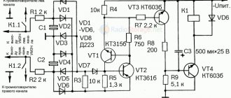
At the time when I was just planning to make my Phoenix-P400 amplifier, I thought in advance that I would have a tone block with electronic control. I found various circuits on imported microcircuits, which were a very big problem for me to get at that time, as well as one very simple and interesting circuit in Radio magazine, which used widely available domestic radio components. This article will talk about a stereophonic tone block with electronic control (push-button), which is built on one microcircuit and two field-effect transistors.
Schematic diagram
So, the article was published in Radio magazine for 1987, number 11 (pages 40 and 41). I will not present this entire article here; for completeness of information, I provide scanned drawings of pages from the magazine: Page 40 Page 41.
The tone block is built on the basis of the K174UN10A microcircuit. In the classic version of the tone block on this chip, variable resistors were used for adjustment, and in this circuit the resistors are replaced with electronic regulators, which are made on KP304A field-effect transistors.
Rice. 1. Schematic diagram of a stereophonic tone block based on the K174UN10A microcircuit and field-effect transistors.
In the circuit you need to use the K174UN10 chip with the letter A - it has the best parameters from the UN10x family. The KP304 field devices were not available, so I replaced them with KP301, everything works fine.
As capacitors C5 and C12, I used K73-11 with a capacity of 0.68 μF, it turns out a little more than those in the circuit, but they will last longer, in principle, you can use more capacious ones that you find at home.
The remaining capacitors, except electrolytic ones, I used tantalum and mica. I didn’t have resistors with high resistance values, so instead of resistors R6 and R17 I used several high-resistance ones connected in series: 2.2M + 2.2M + 750K + 750K. To power the circuit, you need a stabilized DC voltage of 14-15V, so you need to provide for this right away.
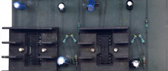
Printed circuit board
The printed circuit board that is presented in the magazine clearly did not suit me, since I needed to save space, as a result I developed my own. I made it on double-sided fiberglass, one side is for the tracks, and the other serves as a screen and minus (common) in the circuit.
Rice. 2. Printed circuit board and arrangement of components on it for the electronic tone control unit on the K174UN10A chip.
The drawings of printed circuit boards are clickable, I described everything, I hope you can understand it clearly and without any problems.
Result
I made two boards for each pair of channels - a total of 4 channels (quad). These are the scarves we got:
Fig.3. Ready-made and debugged electronic tone block boards based on K174UN10A.
Attention: do not pay attention to the jumper that is on the side of the tracks on the board, I made a slight mistake when wiring the signet, then I cut the wrong track and soldered the jumper. Changes have already been made to the printed circuit board stencils, everything is correct there!
Both boards started working immediately and without problems, we only had to set the desired initial tone level using variable resistors R12 and R23. It’s difficult to judge the sound quality of this tone block now - at that time, during testing, I liked everything and the sound quality was quite satisfactory.
In conclusion
If I were making an electronic tone block now, it would obviously not be on the K174UN10 chip. As a good alternative to this tone block, you can consider circuits based on KR174XA53, KR174XA54 microcircuits or other more functional ones with a low harmonic coefficient.
ph0en1x.net