The JLH audio power amplifier , operating in class “A”, has successfully survived to this day since its birth back in 1969. A number of modifications were aimed at improving its parameters, as well as replacing the outdated element base with a more modern one.
But it didn’t end with the 1996 version of the scheme. Later, new modifications and improvements appeared, which we will introduce you to in this part of the article.
Much work on improving the JLH amplifier was carried out by John Linsley Hood's friend, musician (classical pianist), music lover and part-time radio amateur Tim Bren.
And this is what happened as a result...
2003 version of the JLH power amplifier:
Click to enlarge
Output voltage adjustment.
Using integrated stabilizers to regulate the zero output voltage (with bipolar power supply) was not the best idea. Firstly, such stabilizers have a fairly high level of their own noise (which is absolutely unnecessary in the first stage!), and secondly, as practice has shown, microcircuits from some manufacturers tend to get excited when working with low currents.
Therefore, in the 2003 modification, Tim replaced the integrated regulator with an active current source (Q5 / Q6). And in addition to reducing the noise level, it received another interesting effect - the drift of the output voltage when the amplifier warmed up was significantly reduced.
Adjusting the quiescent current of the amplifier output stage.
It has often been written on forums that an amplifier with the option to adjust the quiescent current of the output stage of the 1969 version sounds better than with the 1996 version. In the simulator the distortion was also less for the 1969 version! Through repeated listening and measurements, Tim found that the 1996 still sounded better.
John suggested that Tim organize the quiescent current regulation using an active current source (Q7 / Q8). In addition to the fact that the simulated distortion for this option was two times lower than for the 1996 circuit, there was also no increase in distortion at low frequencies due to the influence of the capacitor. In addition, the output power of the amplifier has increased, since with this modification the output voltage range has increased.
Tim implemented the suggested improvement and after listening, he agreed that the second current source was also a very useful improvement.
↑ Listening material
formed almost spontaneously and consisted of 10 CDs: 1. Dire Straits.
Communigue. Vertigo 800 052-2. 2. Pink Floyd. The final cut. CDP104. 3. Robert Plant – 1993. If I Were Carpenter (Fontana, 858 091-2, CD Single). 4. Roger Waters. The Pros And Cons Of Hitch Hiking. CK 39290. 5. Valery Obodzinsky. These eyes are opposite. MEL CD 60 00351. 6. Vladimir Kuzmin. Heavenly attraction. SZCD 0373-95. 7. Mussorgsky M. Pictures from an exhibition. Conductor Evgeny Svetlanov. SUCD 10-00139. 8. Audio Store. Test – CD1. DL-024. 9. ABBEY ROAD NOW! 10. Faith No More - Introduce Yourself. Slash, Rhino, R2 79940, USA The last two discs from the above list were downloaded from the Internet in losless format, for informational purposes :yes: .
Feedback circuit capacitor.
On many forums, many repeaters of the JLH amplifier wrote about a very noticeable improvement in sound quality when removing the electrolytic capacitor in the feedback circuit (C4).
This modification should be treated with VERY CARE !!! When the capacitor is removed, the depth of the overall direct current feedback significantly decreases (versus 100% in the presence of a capacitor in the circuit), resulting in an increase in the output voltage drift.
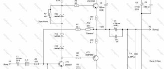
Tim carried out the necessary experiments and this is what happened. You can reduce drift when the amplifier heats up by optimally placing the input stage transistors (Q4, Q5, Q6). They need to be placed as close to each other as possible, ideally pressed against each other. Secondly, one more adjustment can be introduced into the first current source (VR3):
Click to enlarge
This resistor minimizes the DC voltage drift at the amplifier output during warm-up. And you will have to do this several times! Through careful adjustment, Tim was able to achieve an output offset of about 50 mV.
We at the editorial office of RadioGazeta also tried to get rid of the capacitor in the feedback circuit on a prototype, but no matter how hard we tried, in our version the voltage drift at the amplifier output during warming up reached 800 mV, which is a rather dangerous value. In any case, with bipolar power supply (and, as a consequence, the absence of a coupling capacitor at the output), for your own peace of mind you should use a speaker protection system .
Perhaps Tim had larger radiators or a different arrangement of elements, although our prototype was without a case and the cooling was quite efficient. However, based on our results, we strongly do not recommend getting rid of this capacitor.
Of course, you can use an integrator to stabilize the output voltage. But many people don’t like this solution in terms of sound. Although, as practice shows, most often all complaints against the integrator are rooted in “crooked” hands. You just need to be able to prepare it, not forgetting that this is a second-order aperiodic circuit. But this is a topic for another discussion. Not about that now.
Removing the capacitor from the feedback circuit also increases the hum level. Remember that the amplifier is single-ended! The background becomes especially noticeable when using highly sensitive acoustics and an unstabilized power supply. Without a capacitor, the amplifier becomes very sensitive to the quality of the supply voltage!!!
You can significantly reduce the background level when using an unstabilized power supply, even if there is a capacitor in the feedback circuit, by introducing an additional capacitor into the first stage current source as shown in the figure:
↑ Additions
[03/21/2016] Headphone amplifier connection diagram
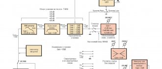
To help beginners avoid common mistakes, I provide a connection diagram for the amplifier board (Fig. 7). Compared to the circuit proposed on our forum, here there is an EMI Filter, a snubber capacitor C1, the inputs are connected by a shielded cable with two signal wires.
Rice. 7. Headphone amplifier wiring diagram
The electromagnetic interference filter is factory-made, for example, type EMI Filter 03 ME 3D, 110/220V, 3A, 50/60Hz. Snubber capacitor 0.033 µF for operating voltage 250V type MKP X2. It can be replaced with 0.033/1kV K78-2 or 0.033/1.6kV K78-2. For installation of input circuits, I recommend a shielded audio cable 2x2x0.14 Shielded Flat Cable OFC.
It is advisable to place the structure in a metal shielding casing made of duralumin or steel.
Amplifier with increased output power.
In principle, the output power of the original version of the JLH amplifier is quite enough for sound at a reasonable volume in an ordinary living room. However, there will always be those who can’t get enough! Low power, low volume, low sensitivity of speaker systems, and so on.
For such music lovers, a circuit with increased output power was developed:
Click to enlarge
When used in conjunction with conventional speakers, this circuit can deliver over 40W of output power, provided the power supply can supply the required current and voltage for your load.
The table below will help you choose the required voltage and current values for a specific power and load resistance:
Click to enlarge
Columns in the table (values measured for resistive load):
- peak output voltage,
- voltage at the output of the power supply,
- current consumption,
- output power at 8 ohm load,
- output power at 6 ohm load,
- output power into a 4 ohm load.
The power dissipated in each output transistor should be limited to approximately 40 to 45 W, assuming that each transistor is equipped with an appropriately sized heatsink.
↑ Details, installation and setup
The sound potential of the amplifier is quite high, so I selected the parts, both in terms of quality and parameters.
BOM (Bill of Materials)
VT1, VT2 - Transistor 2N2907A TO-92 - 4 pcs., VT3 - Transistor 2N2222A - 2 pcs., VT4, VT5 - Transistor 2SC1827 (replacement - 2N4922, BD239, TIP41C or BD243C) - 4 pcs., VD1, VD2 - Diode 1N4148 - 4 pcs., VD3 - Zener diode BZX55C2V7 (2.7V 0.5W) - 2 pcs., VD4...VD7 - Diode 1N4007 (1000V; 1A), 1N4007 (1A/1000V) rectifier diode - 4 pcs., DA1 - Integral stabilizer 7812API (12V; 1.0A), L7812CT linear stabilizer 12V 1.5A - 1 pc., DA2 - Integral stabilizer 7912PI insulated. — 1 pc., R0 — Res. 2x10 for nut d=16 L=15 - 1 pc., Adjustment handle.46108 plastic, D13.3mm. – 1 pc., R1 — Res.-0.25-220 k (red, red, yellow, golden) — 2 pcs., R2 — Res. 10k substr. 3266W-1-103, multi-turn resistor (potentiometer) 3296W, 10 kOhm - 2 pcs., R3, R6, R7, R10 - Res. -0.25-4.7 k (yellow, purple, red, gold) - 8 pcs., R4 - Res.-0.25-2.2 k (red, red, red, golden) - 2 pcs., R5, R11 - Res.-0.25-1 k (brown, black, red, golden) - 4 pcs., R8 - Res.-0.125-470 Ohm (yellow, purple, brown, golden) - 2 pcs., R9 - Res.-0.25-100 Ohm (brown, black, brown, golden) — 2 pcs., R12 — Res.-0.5-5.1 Ohm (green, brown, golden, golden) — 2 pcs., R13 — Res.-0.5-22 Ohm (red, red, black, golden) - 2 pcs., R14 - Res.-0.5-2.2 Ohm (red, red, golden, golden) - 2 pcs., C1 - Cond. 1/63V MKT, Capacitor 1.0uF 100V (Suntan, polyester, pitch: 15) - 2 pcs., C2, C4, C7, C8 - Cond. 100/25V 0611+105°C - 8 pcs., C3, C6 , C9, C11, C17, C18, C19 – C22 - Cond.0.1/63V MKT - 14 pcs., C5 - Cond. NPO 220pF 5% ceramic imp., FKP2 220pF 100V, WIMA, 5mm - 2 pcs. , C10 - Cond.330p/63V J EVOX, FKP2 330pF 100V, WIMA, 5mm - 2 pcs., C12 - Cond.0.033/63V J MKT (0.033/100V J MKT) - 2 pcs., C13 - C16, C23 - C26 - Cond. 2200/25V 1320+105°C, Capacitor 2200.0 uF x 25V Jamicon - 8 pcs., HL1, HL2 - LED BL-BX1341 green.d=3, LED XFT30-G (3mm, tower, green) – 2 pcs., TV-03BC terminal block 3K pitch 5 mm per board, screw terminal block DG126-5.0-03P on a printed circuit board, 3pin. – 1 pc., TV-01A terminal block 2K pitch 5 mm, screw terminal block DG126-5.0-02P on a printed circuit board, 2pin. – 2 pcs., WF-3 plug for 2.54mm board – 1 pc., HU-3 socket for cable – 1 pc., RCA insulated mounting socket (red, black) – 1 pc., 6.3 socket stereo universal plast. 1.078 – 1 pc., Transformer TPG-18-2x12 V (rated load current 0.75 A; input voltage 220 V is supplied to pins 1 - 10, a jumper is placed between pins 4 – 7) – 1 pc., Button switch 220 V 2pin SWR-41(RWB-201), 3A/250V, latch fastening, Panel switch KCD1 (2pin, 6A/250V) – 1 pc., PSU socket with fuse AS-7 (10A/250V) – 1 pc. ., Fuse 0.25A/250V (d=5;L=20) glass. - 1 PC.,
First I installed 11 jumpers made of tinned copper wire with a diameter of 0.7 mm, then fixed resistors and diodes, then capacitors, transistors, and finally connectors, a dual variable resistor, transistors and microcircuits placed on the radiators. “I went through” all the resistors and made sure that their values corresponded to the circuit. The first startup did not go as smoothly as we would like. The negative power stabilizer turned out to be defective, which got very hot and output -1.8 V instead of the required -12 V. Replacing the 7912 microcircuit corrected the situation. The zero at the output is set by trimming resistor R2 (R2′) after 15...20 minutes of warming up and from switching on to switching on the amplifier is kept at a level of ±4...6 mV, which is normal. All setup actually comes down to setting zero and checking the current of the output stage by the voltage drop across resistor R12 (0.64 V). I “drove” the amplifier from a sinusoidal audio frequency generator to the equivalent load - a 33 Ohm, 2 W resistor. There are no signs of self-excitation or unstable operation of the amplifier. When a triangular signal is applied to the amplifier input and the input voltage is slowly increased, the output signal is limited symmetrically on the oscilloscope screen.
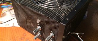
Amplifier design.
As one radio amateur who repeated this design wrote, EVERYTHING gets hot in this amplifier! Starting from the transformer and power supply diodes and ending with the output transistors. Therefore, when repeating this power amplifier, it is necessary to ensure effective heat removal from the structural elements. That is, you will definitely have to use radiators of appropriate (impressive) sizes, ensure air circulation inside the case, for which ventilation holes should be provided in the case.
Use such an amplifier in small rooms, especially in hot weather, with caution due to possible overheating. It is recommended to use thermal protection devices. If it is impossible to provide sufficiently effective passive cooling, additional airflow must be used. This is especially true for those who like to increase the quiescent current.
It is strongly recommended not to use silicone gaskets when installing elements to the radiator. Only thin mica or ceramics. According to reviews from the same radio amateur, the normal temperature of the case of a heated JLH amplifier is about 60°C (about 55°C inside). So listening to music on hot summer days...
↑ Advantages of headphones compared to speaker systems
Headphones (headphones) are used in household equipment as a means of high-quality sound reproduction.
Headphones can replace high-quality speaker systems at much lower material costs. The parameters of some headphones for home listening are given in table. 1. It should be noted that the sensitivity (efficiency) declared for a number of headphone models is somewhat overestimated.
I really love listening to a newly purchased album on my headphones, enjoying truly great music or being disappointed by a bad purchase.
Compared to acoustic systems, headphones have a better stereo effect and effectively reproduce sound signals starting from a frequency of 10...20 Hz. At first glance, an insignificant difference in the lower limit of reproduced frequencies at “some” 15...30 Hz radically affects the sound quality.
In addition, the frequency characteristics of headphones, unlike acoustic systems, do not suffer from mechanical resonance in the low frequency region and have much smoother characteristics. The nonlinear distortions introduced by headphones into the original sound signal are significantly less than in speaker systems, which makes their sound clean and transparent.
The list of advantages of headphones goes on. This is the ability to provide sound pressure corresponding to the original sound of the phonogram with a small input power, better transient response, no interference for surrounding people, etc.
So, headphones do not replace speaker systems, but they allow you to create comfortable listening conditions in unfavorable environments.
Variations on a theme.
Our story would not be complete without mentioning its various clones. Of course, there were attempts to do the same with field-effect transistors. And the notorious Nelson Pass did this.
The figure shows the topology of his amplifier, which he called PLH (Field Linsley Hood):
Schematic diagram of the PLH power amplifier:
With the same output power, according to the author, this amplifier has four times better linearity than the JLH amplifier, with approximately the same output impedance and a much smaller depth of overall negative feedback, which provides even better and more natural sound.
JLH headphone amplifiers are also discussed, repeated on the Internet, and sold on AliExpress both in the form of sets and as ready-made designs.
There are many versions, for example we give this one:
Click to enlarge
As you can see, the Chinese put into production the 1996 circuit, slightly changing the bias circuits of the first stage. And the denominations of some elements raise questions...
This is where we end the history of the development of the JLH power amplifier, but we don’t put an end to it - the popularity of the circuit continues unabated. Next time we'll talk about the power supply for the JLH power amplifier.
↑ List of cited sources
1. Smith P. Studio Series – Stereo Headphone Amplifier. A Top – Class Unit For Audio Enthusiast! // Everyday Practical Electronics, 2008, No. 3, p. 12 – 20. 2. Nosov V. About “harmful sound” // Radio, 2001, No. 11, p. 14, 15. 3. JHL Class A Headphone amplifier - Radio forum at Datagor 4. JLH Class A amplifier for headphones 5. Vasiliev V.A. Foreign amateur radio designs. – M.: Radio and Communications, 1982. – 96 p. (pp. 14 – 16). 6. Digest // Radiohobby, 2004, No. 3, p. 12, 13 (In memory of John Linsley Hood. Amplifier model 1969). 7. A simple headphone amplifier on the KT315B. Datagor article. 8. JLH low voltage amplifier. Datagore forum.