The circuit of a push-button potentiometer (dual) with digital control is based on a specialized DS1267 microcircuit from the Dallas company. This project uses the 100k version. It is controlled by the ATTiny13 microcontroller, chosen due to its small size. The potentiometer allows a maximum of 256 steps to be adjusted, however a limited value of up to 128 steps can be applied. This indicator can be freely set by changing the source code of the program. The board also provides a polarization pin for the DS1267 system, the so-called “VBias,” which can be polarized with a negative voltage when moving signal amplitudes greater than 0.5 V is required.
The device can successfully replace the classic potentiometer (volume control), which was tested on this homemade amplifier.
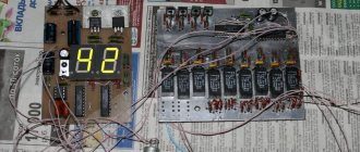
The regulator circuit uses mainly SMD elements to reduce its size as much as possible. The board can be successfully built into any part of a sound amplifier, since its height is only 1 cm. Volume adjustment is carried out using two miniature buttons (micrics) soldered directly to the board. The LED flashes to indicate the process of pressing and adjustment.
Electrical diagram of a push-button regulator
Schematic diagram of a push-button potentiometer regulator.
The basis of the circuit is the microcontroller U1 (ATTiny13), operating on an internal synchronization source (internal oscillator). It controls the state of U2 (DS1267) via a three-wire bus. The outputs of the potentiometers will be connectors P1 and P2. Diode D1, together with a resistor that limits its current, serves as an indicator of bus operation. A short flash indicates the fact of sending data to m/s U2. Capacitor C1 (100nF) is a power filter.
Project diagram
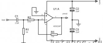
The diagram of a digital audio level controller on Arduino and a PT2258 chip is shown in the following figure.
For demonstration purposes, the circuit is assembled on a breadboard.
Note : All components on the breadboard should be placed as close together as possible to reduce the influence of parasitic capacitances and inductances.
Manufacturing of the structure
The circuit is soldered on a printed circuit board made of foil fiberglass. The board does not contain jumpers, and two apparent breaks in the ground circuit will be the soldering points for the button housing. Installation should begin with soldering integrated circuits, because this is done much more conveniently when there are no protruding elements from the other side. The soldering order of the remaining elements is arbitrary. The circuit must be powered with a voltage of 5 V, preferably stabilized.
Useful: Simple charger for power tools
Boards ready for soldering
Programming the microcontroller is a certain inconvenience, since there is no programming connector. To program MK U1, carefully solder thin wires to its terminals, which will then be connected to the programmer. The VB (VBias) pin is connected to circuit ground, however, if you need to connect this input to a different polarity, simply cut a piece of the track between the pins on the board. When the potentiometer is operated to adjust the volume of the preamp and the amplitude of the signal applied to it does not exceed 0.5 volts, then the VB output should be polarized with respect to a negative voltage of -5 V relative to ground. This will ensure correct analog signal transmission.
push-button regulator – potentiometer
Please note that the potentiometer has a maximum allowable voltage that can be present on any of the pins (relative to GND) from -0.1 to +7 V for Vb = 0 and from -5 to +7 V for Vb = -5 V. When operating the regulator, care should be taken not to exceed the specified permissible voltage limits. When you are powering the circuit from a separate power supply, you need to make sure that the potentiometer ground (GND) and the destination circuit ground are connected.
Fuse bits
The figure shows the fuse settings for the ATTiny13 microcontroller
How are the headphone controls arranged?
The headphone volume control only has two capacitors. A distinctive feature of such devices is their low throughput. The signal in many models takes a long time. This is due to the fact that transistors are not designed for high power. Some models of regulators have resonators installed. They exist in different types and have their own parameters. The most common ones are quartz resonators. Their resistance parameter reaches 4 ohms. In turn, ferrite analogues can only withstand 2 ohms. The volume control for the headphones is connected to the speaker using a throttle.
Regulator control
Working with the circuit is simple. The volume is changed by pressing the S1 and S2 buttons. Holding down the button causes the imaginary potentiometer slider to smoothly move in the desired direction. LED D1 blinks to indicate that the slider position has changed. When it reaches one of the extreme positions, the indicator will stop flashing, although you will continue to press the button.
Regulator connection
How to set up a regulator in Windows?
Setting up the controller is quite simple. The icon for this item is located on the Start panel. By clicking on it once with the left key, you can change the limit frequency. In some cases, the user does not see the specified icon. This happens because the Windows volume control is not added to the notification area. Usually it is transferred automatically by the operating system. However, this action can also be performed manually through the control panel. The reason may also be the absence of the Sndvol.exe file. In this case, a copy of it must be saved on your computer.
How does a thin-compensated regulator work?
Regulators of this type are mainly used in radios. Their system is quite simple. The microcircuit in the device is installed in the “KR2” series. The controller itself is of a linear type. Only one transistor is used. It is located next to the microcircuit.
There are only two capacitors. Most often you can find the electrolytic type. They can withstand a rated power of 16 V. However, the output signal is perceived rather poorly by the device. There are no more than five resistors in the regulator. All of them are set with a maximum frequency of about 3000 Hz.
Using Active Models
An active volume control is usually used for receivers whose power does not exceed 5 V. It contains resistors with a resistance of about 4 ohms. Quartz resonators are installed. A distinctive feature of these regulators can be called signal relays. Chokes, as a rule, are not used in devices. Amplifiers are specified only as operational type. In this regard, there is no need for rectifiers. You can find a wide variety of display systems in devices. This volume control is not suitable for mobile devices.
VOLUME CONTROLSCHEMES OVERVIEW
This article brings to the attention of readers a number of tone controls that differ in circuit design and functionality, which can be used by radio amateurs in the development and modernization of sound reproducing equipment.
The main disadvantage of the recently popular active tone controls is the use of deep frequency-dependent feedback and the large additional distortions they introduce into the controlled signal. This is why it is advisable to use passive regulators in high-quality equipment. True, they are not without shortcomings. The largest of these is the significant signal attenuation corresponding to the control range. But since the depth of timbre control in modern sound-reproducing equipment is small (no more than 8...10 dB), in most cases it is not necessary to introduce additional amplification stages into the signal path.
Another, not so significant drawback of such regulators is the need to use variable resistors with an exponential dependence of the resistance on the angle of rotation of the engine (group “B”), ensuring smooth regulation. However, the simplicity of the design and high quality indicators still incline designers to use passive tone controls.
It should be noted that these regulators require a low output impedance of the preceding stage and a high input impedance of the subsequent one.
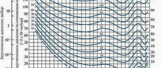
Developed by the English engineer Baxandal back in 1952, the tone control [1] has become perhaps the most common frequency corrector in electroacoustics. Its classic version consists of two first-order filter links forming a bridge - low-frequency R1C1R3C2R2 and high-frequency C3R5C4R6R7 (Fig. 1a). The approximate logarithmic amplitude-frequency characteristics (LAFC) of such a regulator are shown in Fig. 1, b. The calculated dependencies for determining the time constants of the inflection points of the LFC are also given there.
Puc.1
Theoretically, the maximum achievable frequency response slope for first-order links is 6 dB per octave, but with practically implemented characteristics, due to the slight difference in inflection frequencies (no more than a decade) and the influence of previous and subsequent stages, it does not exceed 4...5 dB per octave. When adjusting the tone, the Baxandal filter only changes the slope of the frequency response without changing the inflection frequencies. The attenuation introduced by the regulator at medium frequencies is determined by the ratio n=R1/R3. The range of regulation of the frequency response depends not only on the attenuation value n, but also on the choice of inflection frequencies of the frequency response; therefore, to increase it, the inflection frequencies are set in the mid-frequency region, which, in turn, is fraught with mutual influence of the adjustments.
In the traditional version of the controller under consideration, R1/R3=C2/C1= =C4/C3=R5/R6=n, R2=R7=n-R1. In this case, an approximate coincidence of the inflection frequencies of the frequency response in the region of its rise and fall is achieved (in the general case they are different), which ensures relatively symmetrical regulation of the frequency response (the decline, even in this case, inevitably turns out to be steeper and more extended). With the commonly used n = 10 (for this case, the minimum values of the element ratings are indicated in Fig. 1,a-3,a) and the choice of crossover frequencies near 1 kHz, the tone control at frequencies of 100 Hz and 10 kHz relative to the frequency of 1 kHz is ±14... 18dB. As noted above, to achieve smooth regulation, variable resistors R2, R7 must have an exponential regulation characteristic (group “B”) and, in addition, to obtain a linear frequency response in the middle position of the regulator slides, the ratio of the resistances of the upper and lower (according to the diagram) sections of the variable resistors should also be equal to n. With “high-end” n = 2...3, which corresponds to the regulation range of ±4...8 dB, it is quite acceptable to use variable resistors with a linear dependence of the resistance on the angle of rotation of the engine (group “A”), but at the same time somewhat The adjustment is coarsened in the region of the decline in the frequency response and stretched in the region of the rise, and a flat frequency response is by no means obtained in the middle position of the regulator sliders. On the other hand, the resistance of the sections of dual variable resistors with a linear dependence is better matched, which reduces the mismatch in the frequency response of the stereo amplifier channels, so that uneven regulation in this case can be considered acceptable.
The presence of resistor R4 is not important; its purpose is to reduce the mutual influence of the links and bring together the inflection frequencies of the frequency response in the region of higher audio frequencies. As a rule, R4= =(0.3…1.2)'R1. As shown below, in some cases it can be abandoned altogether. To reduce the influence of the preceding and subsequent stages on the regulator, their output Rout and input Rin resistances must be Rout<>R2, respectively.
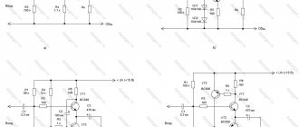
The above “basic” version of the volume control is usually used in high-end radio equipment. In household equipment, a somewhat simplified version is used (Fig. 2a). The approximate logarithmic amplitude-frequency characteristics (LAFC) of such a regulator are shown in Fig. 2.6. Simplification of its high-frequency section led to some vagueness of regulation in the region of higher frequencies and to a more noticeable influence of the preceding and subsequent cascades on the frequency response in this region.
Puc.2
A similar corrector at n=2 (with variable resistors of group “A”) was especially popular in simple amateur amplifiers [2] in the late 60s - early 70s (mainly due to low attenuation), but soon the value of n has increased to the values we are used to today. Everything said above regarding the range of regulation, coordination and selection of regulators is also true for a simplified version of the corrector.
If we abandon the requirement for symmetrical regulation of the frequency response in the sections of their rise and fall (by the way, the need for a decline practically does not arise), then the circuit can be further simplified (Fig. 3, a). Shown in Fig. The LFC of the regulator corresponds to the extreme positions of the resistor sliders R2, R4. The advantage of such a regulator is its simplicity, but since all its characteristics are interconnected, for ease of regulation it is advisable to choose n=3...10. As n increases, the steepness of the rise increases, and the slope of the decline decreases. Everything said above about traditional versions of the Baxandal corrector fully applies to this extremely simplified version.
Puc.3
However, the Baxandal tone control circuit and its variants are by no means the only possible implementation of a passive two-band tone control. The second group of regulators is made not on the basis of bridges, but on the basis of a frequency-dependent voltage divider. An example of an elegant circuit design for a regulator is the tone block, which was once used in various variations in tube amplifiers for electric guitars. The “highlight” of this regulator is the change in the inflection frequencies of the frequency response during the tone control process, which leads to interesting effects in the sound of a “classical” electric guitar. Its basic diagram is shown in Fig. 4a, and the approximated LFCs are shown in Fig. 4.6. Calculated dependencies for determining the time constants of inflection points are also given there.
Figure 4
It is easy to notice that adjustment in the region of lower audio frequencies changes the inflection frequencies without changing the slope of the frequency response. When the variable resistor R4 slider is in the lower (according to the circuit) position, the frequency response at lower frequencies is linear. When you move the slider up, a rise appears on it, and the inflection point during the regulation process shifts to the region of lower frequencies. With further movement of the engine, the upper (according to the diagram) section of resistor R4 begins to bypass resistor R2, which causes a shift of the high-frequency inflection point to the region of higher frequencies. Thus, when regulating, the rise of low frequencies is complemented by a decline of mid frequencies. The high-frequency regulator is a simple first-order filter and has no special features.
Based on this circuit, you can build several variants of tone blocks that allow you to adjust the frequency response in the region of lower and higher frequencies. Moreover, in the region of lower frequencies both a rise and a fall in the frequency response is possible, but at higher frequencies there is only a rise.
A variant of the tone block with regulation of the frequency response bending frequency in the low-frequency region is shown in Fig. 5,a, its LACCH is in Fig. 5.6. Resistor R2 regulates the inflection frequency of the frequency response, and R5 controls its slope. The joint action of regulators allows for significant limits and greater regulatory flexibility.
Puc.5
A diagram of a simplified version of the tone block is shown in Fig. 6,a, its LACCH is in Fig. 6.6. It is, in essence, a hybrid of the low-frequency section of the timbre block shown in Fig. 3,a, and the high-frequency section of the tone block shown in Fig. 4,a.
Figure 6
By combining the functions of adjusting the frequency response in the low-frequency and high-frequency regions, you can get a simple combined tone control with one control, very convenient for use in radio and automotive equipment. Its circuit diagram is shown in Fig. 7,a and LACCH - in Fig. 7.6. In the lower (according to the diagram) position of the variable resistor R1, the frequency response is close to linear over the entire frequency range. When moving it upward, a rise appears at lower frequencies, and the low-frequency inflection point during the regulation process shifts to the region of lower frequencies. With further movement of the engine, the upper (according to the diagram) section of resistor R1 turns on capacitor C1, which leads to a rise in higher frequencies.
Figure 7
When replacing the variable resistor R1 with a switch (Fig. 8a and 8.6), the considered regulator turns into the simplest tone register (position 1 - classic; 2 - jazz; 3 - rock), popular in the 50s - 60s and again used in equalizers of radios and stereos in the 90s.
Figure 8
Despite the fact that it would seem that everything has been said a long time ago about tone control, the variety of passive correction circuits is not limited to the proposed options. Many forgotten circuit solutions are now experiencing a rebirth at a new qualitative level. Very promising, for example, is a volume control with separate adjustment of loudness compensation for low and high frequencies [Z].
LITERATURE
1. Shkritek P. Reference manual on audio circuitry (translated from German). - M.: Mir, 1991, p. 151-153.
2. Krylov G. Broadband ULF. - Radio, 1973, N 9, p.56,57.
3. Shikhatov A. Combined frequency response control unit. - Radio, 1993, N 7, p. 16.
A. SHIKHATOV, Moscow
(Radio 1-99)
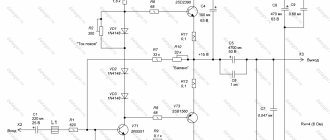
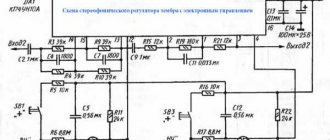
Not a bad reviewer, but another regulator option is missing; the circuit diagram is given below. The only drawback of this volume-timbre control is the need for an output stage of preamplifiers capable of operating at a load of 10k, since at a minimum volume level the variable resistor slider will be connected to the common wire.
Site administration address